
A warehouse robot rounds a familiar aisle, then abruptly slows down. Its wheel encoders say it has traveled three meters. Its camera sees shelves. Its laser scanner sees a clear path. Yet the robot is not sure which aisle it occupies—or whether the turn it just made was real.
This is what navigation failure often looks like in practice: not a dramatic crash, but a growing mismatch between a robot’s internal belief and the physical world. A delivery rover hesitates at a doorway, a drone drifts near a wall, or a mobile manipulator reaches the correct room but faces the wrong direction.
Reliable navigation matters because a robot’s other capabilities depend on it. A flawless gripper cannot pick the right item if the vehicle is in the wrong bay. A safe autonomous vehicle cannot plan a safe route if its position estimate is unreliable.
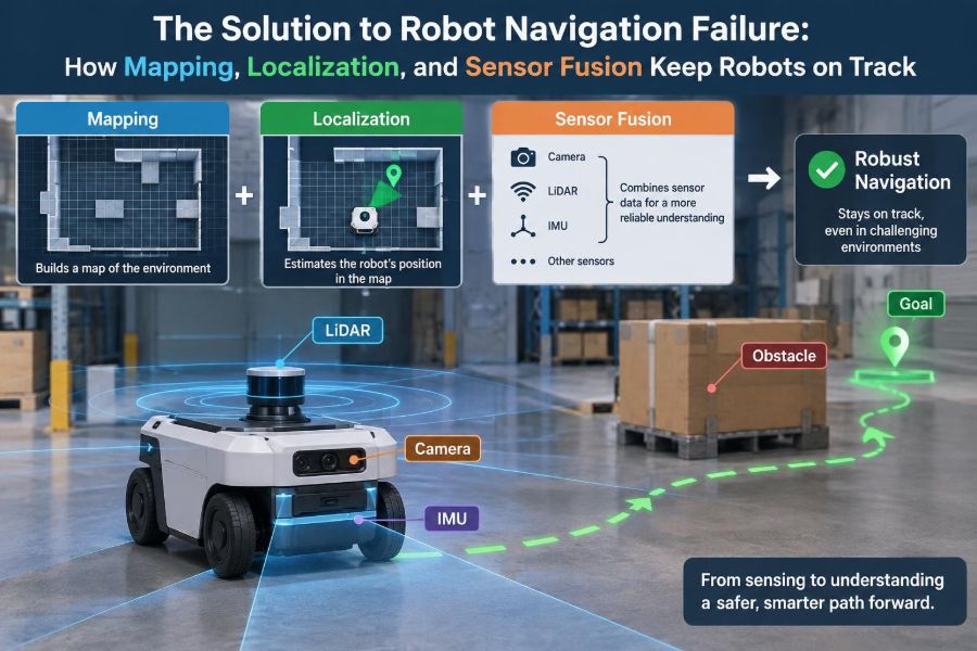
The solution is rarely a single “better sensor.” Robust robots build and maintain a coherent estimate of where they are, what surrounds them, and how uncertain that estimate is. Mapping, localization, and sensor fusion are the systems that make that possible.
🧭 Navigation Is a Continuous Estimation Problem
Robot navigation is commonly described as moving from point A to point B. Under the hood, it is a repeated estimation loop: observe the world, estimate the robot’s pose, choose an action, move, and observe again.
A robot’s pose is its position and orientation. On a flat floor, it is often represented as x, y, θ: horizontal location, vertical location, and heading angle. A robot can be near the correct coordinates but still fail if its orientation is wrong.
Every estimate contains uncertainty. Sensors have noise, wheels slip, features disappear, and maps become outdated. Good navigation therefore does not pretend uncertainty is absent; it models and manages it.
📍 The Three Jobs: Mapping, Localization, and Planning
Navigation has several connected jobs that are easy to confuse. Mapping answers, “What does the environment look like?” Localization answers, “Where am I within it?” Planning answers, “What route and motion should I take next?”
Mapping and localization supply the spatial context that planners need. A global planner may select a route through rooms or aisles, while a local planner continually chooses safe motions around people, carts, or other short-term obstacles.
A navigation stack can have an excellent planner and still fail if its map or pose is wrong. Planning is only as trustworthy as the spatial model fed into it.
🗺️ What a Robot Map Actually Represents
A map is not necessarily a photographic picture. It is a structured representation selected for a task, sensor suite, environment size, and available computing power.
For indoor ground robots, an occupancy grid is common. It divides space into small cells and assigns each one a belief such as occupied, free, or unknown. A laser scan can then be compared with walls, shelving, and other stable structures in that grid.
Other maps represent landmarks, geometric lines, dense point clouds, visual features, or semantic objects such as doors and charging stations. The useful question is not “Which map is best?” but “Which representation preserves the information this robot needs?”
🧱 Static Structure Makes the Best Localization Reference
Localization works best when a robot compares measurements with features that persist. Building walls, pillars, fixed racks, curb edges, and carefully surveyed markers are usually better references than people, forklifts, or open doors.
Dynamic objects can dominate a sensor reading in busy environments. If a robot treats a moving pallet as a permanent wall, it may distort its own position estimate or corrupt a map built online.
Practical systems filter known dynamic classes when possible and favor broad, stable geometry. In a warehouse, the end faces of long shelving runs may be more useful than the clutter inside each aisle.
📐 Coordinate Frames Prevent Quiet, Expensive Errors
Robots reason in multiple coordinate frames. A map frame gives a long-term global reference. An odom frame tracks locally smooth motion estimates. A base frame sits on the robot, while each sensor has its own frame.
Transforms describe the fixed or changing relationship between these frames. If a lidar is mounted five centimeters ahead of the robot center but software assumes it is centered, every scan alignment can be biased.
Frame mistakes are especially dangerous because they can look plausible. The robot may navigate adequately in one direction and consistently clip corners or stop too early in another.
⚙️ Odometry Is Useful Even When It Drifts
Odometry estimates motion from wheel encoders, joint measurements, visual motion, or inertial sensors. For a wheeled robot, encoder pulses indicate how far wheels appear to have rotated; kinematic equations convert that motion into a changing pose.
Odometry is valuable because it is fast, continuous, and available between richer sensor updates. It helps predict where the robot should be before a lidar scan or camera frame arrives.
Its weakness is accumulation. Small wheel-radius errors, uneven floors, wheel slip, and imperfect turning models compound over time. Odometry can be locally smooth while becoming globally incorrect.
🛞 Wheel Slip Turns Motion Into Misinformation
Wheel odometry assumes a relationship between wheel rotation and ground travel. That assumption weakens on dust, ramps, wet surfaces, loose carpet, polished concrete, or when a robot accelerates aggressively.
A differential-drive robot can also scrub its wheels during turns: the wheels rotate as though the robot followed an ideal arc, but friction changes the actual motion. Carrying a load can alter traction and suspension enough to change the error pattern.
Teams should test odometry in the operating environment, not only on a smooth laboratory floor. Calibration values obtained under one payload and surface condition may not transfer cleanly to another.
🧪 IMUs Sense Motion, Not Absolute Position
An inertial measurement unit, or IMU, typically measures angular velocity and linear acceleration. Gyroscopes are particularly useful for tracking rapid rotations, helping a robot remain stable when wheel odometry is unreliable during a turn.
Acceleration must be integrated once for velocity and again for position. Any tiny bias is also integrated, so a free-running IMU position estimate drifts quickly. Gravity compensation and sensor orientation further complicate the calculation.
IMUs are therefore best treated as a complementary motion sensor rather than a stand-alone indoor positioning system. They add short-term responsiveness while maps, landmarks, or global signals constrain long-term drift.
📡 Lidar Measures Shape With Strong Geometric Clues
Lidar estimates range by timing reflected laser light. A two-dimensional lidar produces a scan of distances in a plane; three-dimensional lidar captures spatial structure across a volume.
Its strength is geometry. Walls, pillars, rack edges, and corners often provide distinctive shapes even when lighting changes. This makes lidar a frequent choice for indoor mobile robots and outdoor machines operating across day and night.
Lidar is not immune to failure. Glass, mirror-like surfaces, rain, dust, dark materials, and partial occlusion can produce missing or misleading returns. A scan also becomes less distinctive in a long, repetitive corridor.
👁️ Cameras Add Appearance and Semantics
Cameras capture texture, color, signs, labels, and object identity. They can recognize a dock marker, detect a person, read a visual code, or distinguish a doorway from a wall—information that a range sensor may not provide.
Visual odometry and visual localization infer movement or position by matching features across images or against a prior map. Stereo cameras add depth through parallax, while monocular systems require motion or prior assumptions to recover scale reliably.
Lighting is the central trade-off. Low light, glare, motion blur, fogged lenses, repetitive texture, and seasonal changes can reduce visual reliability. Camera systems need exposure management, clean optics, and realistic testing in difficult scenes.
📶 Global Signals Help, but They Have Boundaries
GNSS, commonly associated with GPS, provides global outdoor positioning when satellite visibility and signal conditions are favorable. It is useful for robots operating over large outdoor areas because it connects navigation to geographic coordinates.
Near buildings, under tree cover, indoors, or in urban areas with reflected signals, accuracy and availability can degrade. GNSS should not be assumed to provide a precise, uninterrupted local pose for every task.
Other infrastructure-based options include ultra-wideband anchors, Wi-Fi-derived positioning, magnetic references, and fixed visual markers. They can be effective within designed spaces, but each introduces installation, maintenance, and calibration requirements.
🔀 Sensor Fusion Combines Complementary Evidence
Sensor fusion combines measurements from multiple sensors to produce a better estimate than any source would provide alone. It does not simply average every input; it weights evidence according to uncertainty, timing, and consistency.
For example, wheel encoders provide frequent motion updates, an IMU improves short-term rotational tracking, and lidar periodically corrects the accumulated drift by matching observed geometry to a map. Each fills a gap left by the others.
Fusion can also make failures visible. If wheel odometry claims forward movement while lidar alignment repeatedly rejects that motion, the system has evidence that slip, blockage, or a sensor problem may be occurring.
📊 Filters Turn Noisy Measurements Into Beliefs
A navigation filter usually alternates between prediction and correction. During prediction, it projects the previous pose forward using a motion model and odometry. During correction, it compares expected sensor readings with actual measurements.
A Kalman filter is effective when uncertainty and system behavior can be approximated with suitable mathematical assumptions. Extended and unscented variants handle some nonlinear relationships commonly found in robotics.
Particle filters represent many possible poses, or particles. Each is scored against sensor observations, weak candidates are removed, and strong candidates are resampled. This is useful when the robot may have several plausible locations, such as similar-looking aisles.
⏱️ Time Synchronization Is Part of Sensor Accuracy
A sensor reading describes the world at a particular instant. If the robot moves while sensors are sampled at different times, treating all measurements as simultaneous creates positional error.
Consider a robot turning quickly. An IMU sample captured at the start of the turn and a camera image captured later may be incorrectly paired unless timestamps and motion compensation are handled carefully.
Consistent clocks, known sensor latency, and timestamped transforms are not implementation details to postpone. They directly affect localization quality, especially on fast robots and drones.
🎯 Calibration Connects Measurements to Reality
Calibration estimates parameters such as wheel radius, wheelbase, camera intrinsics, lidar mounting pose, and the fixed transform between sensors. A fusion algorithm cannot compensate indefinitely for a sensor installed at the wrong assumed angle.
Extrinsic calibration concerns where a sensor sits relative to the robot body. Intrinsic calibration concerns the sensor’s internal measurement model, such as a camera’s focal properties and lens distortion.
Recalibration is sensible after collisions, maintenance, payload changes that flex a mount, or any hardware modification. Treat calibration values as configuration that must be verified, not permanent truth.
🧩 Scan Matching Anchors a Robot to a Known Map
When a lidar-equipped robot localizes against a prior map, it searches for the pose at which its current scan best aligns with expected obstacles. This process is broadly called scan matching.
A good match can strongly correct odometry drift. A poor match can pull the estimate toward the wrong part of the map, particularly where identical rack rows or featureless walls create multiple plausible alignments.
Robust systems restrict impossible jumps using the previous pose and uncertainty estimate. They also use quality scores or innovation checks to reject observations that do not agree sufficiently with the current belief.
🧠 SLAM Builds a Map While Estimating Pose
Simultaneous localization and mapping, or SLAM, addresses the case where neither a complete map nor a known pose is available. The robot estimates both together as it explores.
SLAM may use lidar, cameras, depth sensors, or combinations of them. It creates a map from observations while using emerging map structure to improve the trajectory estimate.
This circular dependency is challenging: a wrong pose creates a distorted map, and a distorted map makes later localization harder. Good SLAM systems preserve uncertainty and use repeated observations to correct earlier estimates.
🔁 Loop Closure Corrects the Long Way Around
Loop closure occurs when a robot recognizes that it has returned to a previously visited place. That recognition provides a powerful constraint: two portions of the estimated trajectory should correspond to the same physical location.
Without loop closure, a robot mapping a large loop may finish near its starting point in reality while its map shows a gap or overlap. With a valid loop closure, optimization can distribute accumulated error across the trajectory.
False loop closures are risky in visually repetitive environments. A system that mistakes one identical aisle for another can bend or duplicate a map, so candidate matches must be checked with geometry and consistency tests.
🏭 Repetitive Environments Create Aliasing
Perceptual aliasing occurs when different locations produce similar sensor observations. Warehouse aisles with identical shelving, hotel corridors with repeated doors, and parking structures with repeated columns are common examples.
In a hypothetical warehouse, a lidar may see the same two parallel rack faces in ten different aisles. A camera may find the same product labels repeated on each shelf. Neither observation alone uniquely identifies the aisle.
Useful remedies include distinctive fiducials at strategic locations, semantic landmarks, wider sensor fields of view, map constraints, and route designs that periodically expose the robot to unique geometry.
🚪 Dynamic Environments Demand Map Discipline
Real environments change. A door that was open during mapping may later be closed. A warehouse may reorganize inventory; an office may add partitions; outdoor vegetation can grow or be trimmed.
There are two different needs here: a stable long-term map for localization and a short-term obstacle layer for immediate safety. Combining them carelessly can cause a temporary cart to become a permanent feature.
Map maintenance should have an explicit process: detect persistent changes, review or validate them where appropriate, update the reference map, and retain rollback options if a bad update is introduced.
🛑 Localization Confidence Should Affect Robot Behavior
A robot should not behave identically when it is well localized and when it is uncertain. Its navigation stack needs a confidence signal, often derived from filter covariance, match quality, innovation residuals, or agreement among sensors.
As confidence falls, sensible behavior may include reducing speed, increasing clearance, requesting a rescan, navigating toward a known landmark, or stopping in a safe location. The correct response depends on the task and hazard level.
A single confidence number is not perfect; models can be overconfident. Still, making uncertainty visible to decision-making is safer than treating every pose estimate as equally credible.
🧯 Recovery Behaviors Turn Confusion Into a Managed Event
Even well-designed systems lose localization. Recovery behaviors provide a controlled response rather than allowing a robot to continue on an untrusted estimate.
- Stop or slow when pose quality falls below a defined threshold.
- Rotate or move slightly to gather more informative sensor observations.
- Return to a known checkpoint, marker, or docking area when safe.
- Reinitialize from a bounded set of possible poses rather than an unrestricted map-wide search.
- Escalate to an operator when automatic recovery cannot establish a credible pose.
Recovery needs testing just as much as normal navigation. A robot that “usually relocalizes” is not enough; engineers need to know what it does while relocalization is uncertain.
🧱 Separate Global Navigation From Local Avoidance
Global localization says where the robot is in the larger map. Local perception says what is immediately around it. Keeping these roles distinct prevents a nearby moving obstacle from unnecessarily changing the global map.
A local costmap, for example, can mark a person or pallet as temporarily blocked space and steer around it. The global map can remain focused on persistent walls, routes, and fixed infrastructure.
This separation also improves debugging. Engineers can ask whether a failure came from the robot’s global pose, its obstacle detection, its local planner, or an interaction among those layers.
🧭 The Route Can Make Localization Easier or Harder
Navigation is not only about following the shortest path. A route through feature-rich space may be more reliable than a marginally shorter route through a blank corridor or repetitive aisle.
This idea is sometimes called active localization: choose actions that improve the robot’s knowledge of its pose. A robot uncertain at an intersection might turn toward a uniquely shaped lobby or a fixed marker before committing to a narrow passage.
The trade-off is time and energy. For low-risk transport, a small detour may be worthwhile; for time-critical tasks, designers may need stronger sensors or infrastructure instead.
🧰 A Practical Debugging Sequence
When a robot goes off course, start with evidence rather than tuning parameters at random. Record raw sensor data, transforms, timestamps, commanded motion, odometry, estimated pose, localization confidence, and the planner’s decisions.
- Verify coordinate-frame conventions and sensor mounting transforms.
- Check timestamp alignment and sensor latency.
- Compare raw odometry with measured motion on representative surfaces.
- Inspect whether map features are current, static, and sufficiently distinctive.
- Measure scan or visual match quality at the failure location.
- Reproduce the case with the same speed, payload, lighting, and traffic conditions when feasible.
This sequence narrows the problem. A planner adjustment cannot fix a camera exposure issue, and a new map cannot fix an incorrect lidar transform.
🧪 Test the Edges, Not Just the Happy Path
A robot that succeeds on an empty, well-lit route has passed only an early test. Navigation should be evaluated around the conditions that challenge the intended deployment.
Useful test cases include slippery transitions, strong sunlight, dim corridors, reflective surfaces, temporary occlusions, moving crowds, repeated structures, delayed data, depleted battery behavior, and changes in payload.
Simulation is valuable for repeatable scenarios and algorithm development, but it may not reproduce sensor artifacts, tire behavior, multipath radio effects, or real clutter perfectly. Field testing remains necessary before relying on a navigation design.
⚖️ More Sensors Are Not Automatically More Reliable
Adding sensors can improve redundancy and observability, but each device also adds power use, data bandwidth, calibration work, failure modes, and opportunities for contradictory measurements.
A cheap sensor with poorly characterized noise can degrade a fusion estimate if given excessive trust. A high-resolution camera may add little in darkness without suitable illumination. A second lidar may help around occlusions but complicate mounting and synchronization.
Choose sensors based on the failure modes that matter most. The aim is not sensor quantity; it is a system whose remaining sensors can support safe behavior when one source becomes unreliable.
🔒 Safety Requires Limits Beyond Localization
Localization supports safe navigation, but it is not the entire safety system. Independent obstacle detection, speed limits, braking capability, emergency stops, geofencing, supervision, and task-specific risk controls may all be necessary.
A highly confident but incorrect estimate can still occur, especially after an unmodeled change or correlated sensor failure. Designing for independent checks reduces reliance on a single chain of assumptions.
The appropriate safeguards depend on robot mass, speed, workspace access, terrain, human proximity, and applicable organizational or regulatory requirements. Engineers should assess the deployed system rather than assuming a navigation algorithm alone makes operation safe.
📈 Build Navigation Around Observable Failures
Strong navigation systems are designed around questions that can be measured: How much does the pose drift after a route? Where do scan matches become ambiguous? How often does confidence drop? Can the robot stop before a bad estimate creates a hazard?
Logging and visualization are essential tools. Overlaying a trajectory on the map, replaying sensor data, and plotting residuals can reveal whether failure begins with wheel slip, a stale transform, a changed scene, or a planner reacting poorly to valid data.
Over time, these observations guide targeted improvements: better map curation, a revised sensor mount, a confidence-aware controller, or infrastructure at only the hardest locations.
🦾 The Core Principle: Keep Belief Tied to Reality
Mapping gives a robot a reference for what should be around it. Localization estimates where it is within that reference. Sensor fusion combines imperfect clues so that temporary weaknesses in one source do not immediately become navigation failure.
The central engineering task is to maintain a credible connection between the robot’s internal pose estimate and the physical environment. That requires accurate frames and calibration, stable map features, time-aware measurements, uncertainty handling, and planned recovery when confidence falls.
Reliable robots do not need perfect sensors or a flawless world. They need an architecture that recognizes imperfect information, checks it against independent evidence, and changes behavior before uncertainty becomes unsafe motion.
When mapping, localization, and sensor fusion are treated as one continuously monitored system, robots can stay on track even when individual measurements do not. 🧭🦾📍