
A warehouse robot rolls toward a shelf, slows down, aligns its lifting arm, and stops with its gripper exactly where it needs to be. From the outside, the motion can look effortless. Inside the machine, though, many decisions are happening every second.
A slight wheel slip, a battery-voltage dip, an unexpected box, or a joint that moves more slowly than expected can turn a simple command into the wrong physical result. A robot cannot rely on intention. It must measure what actually happened and respond.
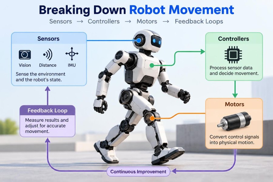
That is the heart of robot movement: sensing the world and the robot’s own body, deciding what to do, applying force through actuators, and checking the outcome. This cycle appears in everything from a hobby rover to an industrial arm and a walking research robot.
Understanding the loop makes motion problems much easier to diagnose. It also explains why a stronger motor alone rarely fixes a robot that moves poorly.
🤖 Robot Motion Is a System, Not a Single Part
When people say a robot “moves,” they may picture a motor turning. A motor is necessary in many robots, but it is only one part of a larger motion system.
That system must establish a goal, estimate the current state, calculate an action, produce mechanical force, and observe the result. If any stage is inaccurate or slow, the robot may overshoot, drift, oscillate, stall, or collide.
A useful mental model is a chain: goal → sensing → control → actuation → physical motion → sensing again. The last step closes the loop.
🎯 Start With the Motion Goal
Controllers need a clear target. “Move forward” is less useful than “drive 0.5 meters while maintaining a heading of zero degrees,” because the second instruction provides measurable conditions.
Goals may describe position, speed, acceleration, orientation, contact force, or a combination. A robotic arm inserting a connector, for example, may need to control both its location and the force it applies.
Good goals also respect physical limits. Asking a heavy arm to reach a distant point instantly creates a demand that no realistic motor, gearbox, or structure can meet safely.
🧭 Degrees of Freedom Define What Can Move
A degree of freedom, often shortened to DOF, is an independent direction in which a mechanism can move. A wheel that spins has one rotational degree of freedom. A drone can translate and rotate in three-dimensional space, giving its body six possible motion directions.
An arm joint adds useful mobility, but it also adds sensing, control, wiring, calibration, and possible error. More DOF does not automatically produce a better robot.
Designers choose enough degrees of freedom for the task. A sorting arm may need multiple rotating joints to reach around obstacles, while a conveyor diverter may only need one controlled pivot.
📐 Coordinate Frames Keep Motion Meaningful
Robots describe locations relative to coordinate frames: named reference systems with an origin and axes. A mobile robot may use a map frame, a frame attached to its chassis, and separate frames on a camera, gripper, and each arm link.
“Move the gripper 10 centimeters left” is ambiguous until “left” is tied to a specific frame. Left relative to the robot is not necessarily left relative to the room.
Errors in frame definitions are a common source of strange behavior. A sign reversal or a camera mounted at a slightly different angle than assumed can make correct-looking calculations generate wrong real-world movement.
📍 Position Sensors Tell the Robot Where It Is
Position sensing answers questions such as: How far has this wheel turned? What angle is this joint at? Has the linear slide reached its travel limit?
Encoders are widely used for this purpose. Incremental encoders report changes from a starting point, while absolute encoders report a position value within their designed range even after power interruption, depending on the device and system arrangement.
Limit switches provide a simpler, binary answer: a mechanism has reached a particular location. They are especially useful during homing, when a robot establishes a known reference position.
🧠 Inertial Sensors Reveal Rotation and Acceleration
An inertial measurement unit, or IMU, commonly combines gyroscopes and accelerometers. Gyroscopes measure angular rate, while accelerometers measure specific force, which includes the effects of gravity and movement.
An IMU helps a balancing robot detect tipping or a drone detect rotation. Yet it is not a perfect orientation sensor by itself. Small biases, vibration, and integration over time can create drift.
Reliable systems commonly combine IMU data with other measurements, such as wheel encoders, cameras, magnetometers where suitable, or known external references. This is called sensor fusion.
👁️ External Sensors Describe the Surroundings
Internal sensors report the robot’s own state. External sensors describe its environment. Cameras, lidar, ultrasonic range sensors, depth cameras, tactile sensors, and force sensors all provide different kinds of evidence.
No sensor sees everything. Cameras can provide rich visual detail but depend on lighting and may struggle with depth in some setups. Lidar can measure ranges accurately in many conditions but does not inherently identify what each object is.
Choosing a sensor starts with the decision it must support, not with a desire for the most sophisticated component.
⚖️ Force and Torque Sensors Add a Sense of Touch
Position control is not enough when contact matters. A robot pushing a door, sanding a surface, or handling fragile items needs some awareness of the forces involved.
Torque is turning force around an axis. It can be measured directly with dedicated sensors or estimated indirectly from motor current and a model of the drivetrain. Indirect estimates can be useful, but friction, gear losses, and changing loads limit their accuracy.
Force sensing enables compliant behavior: the robot can yield slightly instead of continuing to push rigidly when it meets an unexpected obstacle.
🧹 Raw Measurements Need Cleaning
Sensor readings are not the same as truth. Electrical noise, mechanical vibration, poor mounting, delayed communication, quantization, and changing temperature can all affect measurements.
Filtering reduces unwanted variation, but aggressive filtering introduces delay. That tradeoff matters: a delayed measurement can make a fast controller react to an old situation.
Engineers often begin by plotting real sensor data during representative motion. A graph can reveal noisy wiring, encoder dropouts, vibration at a particular speed, or a sensor range that does not fit the task.
🔄 State Estimation Connects Incomplete Clues
A robot rarely measures every variable it needs directly. State estimation combines sensor readings and a motion model to estimate quantities such as velocity, orientation, or location.
Consider a wheeled robot. Encoders estimate distance traveled, but wheel slip can make that estimate wrong. A camera may recognize features in the environment, but its updates can be slower. Combining the evidence can be more reliable than trusting either source alone.
An estimate still has uncertainty. Robust robots account for that uncertainty rather than treating every calculated value as exact.
🗺️ Localization Answers “Where Am I?”
Localization is the process of estimating a robot’s position and orientation in a meaningful environment or map. It is central to autonomous navigation, but it also matters for an arm that must know where its base is relative to a workcell.
Dead reckoning uses prior motion estimates, such as wheel turns, to update position. It is simple and useful over short distances, but errors accumulate.
External observations can correct drift. Examples include visual markers, lidar map matching, satellite positioning in appropriate outdoor applications, or fixed reference beacons. Each approach has failure modes that should be understood before deployment.
🧮 The Controller Converts Error Into Action
A controller compares the desired state with the estimated current state. The difference is called the error. It then calculates a command, such as motor voltage, current target, torque request, or desired wheel speed.
If a joint should be at 45 degrees but is at 40, the controller commands motion in the direction that reduces the error. As the joint approaches the target, the command generally needs to change.
Without this decision-making layer, a robot would only execute fixed outputs and hope that the physical world behaves exactly as expected.
📈 PID Control Is a Practical Foundation
PID control is common because it is understandable, computationally light, and effective for many regulated motions. Its three terms respond to the present, accumulated, and changing portions of error.
| Term | What it responds to | Typical effect |
|---|---|---|
| Proportional (P) | Current error | Pushes harder when far from the target |
| Integral (I) | Accumulated error over time | Helps remove persistent offset |
| Derivative (D) | Rate of error change | Can damp overshoot and rapid changes |
PID is not magic. It depends on sensible gains, adequate sensors, correct sign conventions, and a mechanical system that can respond predictably enough for the control rate.
🎛️ Tuning Means Managing Tradeoffs
High proportional gain can make a system respond quickly, but too much can cause overshoot or sustained oscillation. Integral action can correct a steady bias, but excessive integral action can build up while an actuator is saturated.
Derivative action can improve damping, yet it is sensitive to noisy signals. In practice, derivative filtering and careful measurement quality are often necessary.
Tuning should happen with safety limits in place. Increase capability gradually, record tests, and change one meaningful parameter at a time. Randomly changing several gains makes it difficult to learn what caused an improvement or failure.
🚦 Feedforward Anticipates Predictable Loads
Feedback reacts to error after the robot observes it. Feedforward uses known information to command an expected effort before a large error develops.
A vertical arm joint is a classic example. Gravity pulls on the arm even when it is perfectly on target. A gravity-compensation feedforward term can supply much of the holding torque, leaving feedback to correct smaller differences.
Feedforward depends on a model, so an inaccurate model can hurt performance. Used carefully alongside feedback, it often reduces lag and controller effort.
⚙️ Motors Turn Electrical Energy Into Motion
Motors generate rotational motion, which mechanisms convert into wheel motion, joint rotation, linear travel, or gripper closure. Common categories include brushed DC motors, brushless DC motors, stepper motors, and servo systems.
Motor selection involves more than speed. Designers consider available torque, operating speed range, thermal limits, supply voltage, mass, efficiency, control electronics, and expected duty cycle.
A motor that performs well for a brief demonstration may overheat during repeated work. Thermal behavior is therefore a system constraint, not an afterthought.
🔋 Torque, Speed, and Power Must Be Matched
Motors generally cannot provide maximum torque at maximum speed. Their available operating range depends on motor characteristics, voltage, current limits, and the load.
Power is related to torque and rotational speed. A robot may need high torque to start moving a load, then need speed once it is already moving. The drivetrain must support both demands in the intended operating range.
Undersized motors can stall; oversized motors add weight, cost, and potentially dangerous force. The right choice follows a load analysis, not a guess based only on physical size.
🦿 Gearboxes Trade Speed for Torque
A gearbox reduces output speed while multiplying available output torque, with losses. It lets a compact motor move a heavier load or hold a position more effectively.
However, gearboxes can introduce backlash: a small amount of free motion when direction reverses. Backlash is especially troublesome in precision positioning because the encoder may report motor motion before the output link has moved.
Gear reduction also affects reflected inertia and responsiveness. Very high reduction can make a joint strong but less backdrivable and less able to react naturally to contact.
🔩 Mechanisms Decide How Motor Motion Reaches the Task
Belts, chains, lead screws, ball screws, gears, linkages, pulleys, and direct-drive joints each transform motor rotation differently. Their selection shapes speed, accuracy, stiffness, maintenance, and noise.
A belt drive may be light and quiet but can stretch under load. A lead screw can create controlled linear motion but may be slower and can experience friction or backlash. Direct drive removes a gearbox but demands a motor sized for the joint torque.
The controller only sees the result of the whole mechanism. Mechanical flexibility or friction can look like a control problem even when the code is correct.
🔁 Open-Loop and Closed-Loop Motion Behave Differently
In open-loop control, the robot sends a command without continuously using the measured result to correct the action. A basic timed motor command is open loop.
In closed-loop control, sensor feedback changes the command as the motion unfolds. Driving a wheel to a measured speed with an encoder is a closed-loop task.
Open loop can be suitable for simple, repeatable, low-risk mechanisms. It becomes fragile when loads change, batteries discharge, surfaces vary, or accuracy matters. Closed loop adds complexity but helps the robot adapt to these real conditions.
🪞 Feedback Loops Continuously Correct Reality
A feedback loop does not make a robot flawless. It makes the robot responsive to the difference between expected and observed behavior.
Imagine commanding two drive motors with identical voltage. On a smooth floor, the robot might travel nearly straight. On carpet, one wheel may encounter more resistance and the robot curves. Wheel-speed feedback can equalize the wheel behavior; heading feedback from an IMU can further correct the path.
This repeated measurement and correction is why feedback is fundamental to reliable movement.
⏱️ Timing and Latency Can Destabilize a Good Design
Control happens at discrete intervals. If sensor updates, calculations, and motor commands arrive too slowly or unpredictably, the controller acts on stale information.
Latency is delay between an event and the system’s response. In a slow-moving mechanism, modest delay may be acceptable. In a balancing robot or fast drone, delay can severely reduce stability margins.
Communication buses, operating-system scheduling, filtering, vision processing, and motor-driver update rates all contribute. Measuring end-to-end timing is more useful than assuming a fast processor alone solves the problem.
📉 Saturation and Integral Windup Need Protection
Actuators have limits: a motor driver cannot deliver unlimited voltage or current, and a joint cannot travel beyond its physical stops. When a controller requests more than the system can deliver, it is in saturation.
If the integral part of a PID controller continues accumulating error during saturation, it can become excessively large. When the robot finally can move, that stored command may cause a strong overshoot. This is known as integral windup.
Common safeguards include clamping the integral term, integrating only in suitable conditions, and designing trajectories that respect motion limits from the start.
🛤️ Trajectories Make Motion Smoother and Safer
A target position alone does not specify a safe journey. A trajectory defines how position, velocity, and often acceleration change over time.
Commanding an arm to jump immediately from one position to another can demand extreme acceleration. A planned trajectory ramps speed up and down, reducing vibration, current spikes, mechanical shock, and tracking error.
For higher-performance systems, designers may also limit jerk, the rate of change of acceleration. Smooth trajectories are not merely aesthetic; they protect hardware and make control easier.
🧱 Robot Dynamics Change the Control Problem
Kinematics describes motion geometry: where a link will be for a given joint configuration. Dynamics adds mass, inertia, gravity, friction, and forces.
A small arm moving freely may track a command well, then behave differently after a heavy tool is attached. The payload changes the torque required and can alter vibration modes.
Simple controllers can still work on dynamic systems, but their limits should be recognized. As speed, precision, payload variation, or interaction forces increase, better modeling and sensing become increasingly valuable.
🛑 Safety Is Part of Motion Engineering
Any moving robot can create pinch points, impact hazards, unexpected starts, or falling loads. Safety cannot be delegated entirely to software because sensors, code, and hardware can fail.
Useful protections may include mechanical hard stops, appropriately designed guards, emergency-stop circuits, current limits, speed limits, watchdog behavior, fault detection, and safe startup procedures. The proper measures depend on the application and environment.
Testing should begin at reduced speed and energy. A robot that is safe at low speed may still become hazardous when commanded to full acceleration with a real payload.
🧪 Test One Layer at a Time
Complex motion failures are easier to solve when the system is tested in layers. First confirm wiring and sensor direction. Then verify a motor can move safely at low output. Next test measured speed or position before integrating navigation, vision, or task logic.
- Check that positive commands produce the intended physical direction.
- Confirm sensor values change in the expected direction and range.
- Log targets, measurements, controller outputs, and fault states.
- Test with realistic load, surface, temperature, and power conditions.
Layered testing prevents a navigation bug, bad encoder sign, and poor PID gains from becoming one confusing symptom.
🐛 Common Motion Problems Have Physical Clues
Oscillation often points to excessive gain, delayed feedback, flexible mechanics, or noisy sensing. A steady position offset may suggest insufficient integral action, gravity load, friction, or a calibration error.
Drifting mobile robots may be experiencing wheel slip, unequal drivetrains, a poor heading estimate, or a changing floor surface. Sudden jerks can indicate backlash, poor trajectory planning, loose components, or intermittent electrical connections.
Symptoms are clues, not diagnoses. Inspect logs and hardware together; treating every problem as a software-tuning issue wastes time.
🧰 Calibration Turns Components Into a System
Calibration establishes the relationship between measurements and the physical world. Examples include encoder zero positions, wheel diameter estimates, camera-to-robot transforms, IMU bias estimates, and force-sensor offsets.
Calibration can change over time. A bumped camera bracket, worn wheel, loose belt, or replaced gearbox may invalidate earlier assumptions.
Build calibration checks into maintenance and startup where practical. A robot with excellent algorithms but incorrect reference values will confidently make incorrect movements.
🏭 The Same Loop Scales Across Robot Types
A line-following rover, collaborative arm, autonomous floor cleaner, quadcopter, and walking robot use different mechanisms, but all rely on the same basic structure.
The rover regulates wheel speeds and heading. The arm regulates joint positions, tool pose, and perhaps contact force. The drone regulates motor thrust to control attitude and position. The walking robot must also manage changing ground contact and balance.
What changes is the complexity of the model, sensor suite, timing requirement, and safety case—not the underlying need to compare desired and measured behavior.
🧩 A Practical Design Sequence
Starting with a motor catalog often leads to expensive redesign. Begin with the task and work outward through the complete motion chain.
- Define the required motion, load, accuracy, speed, environment, and safety constraints.
- Select a mechanism that can physically produce the needed motion.
- Estimate forces, torque, speeds, duty cycle, and power needs.
- Choose sensors that observe critical states and likely disturbances.
- Develop control and trajectories within known hardware limits.
- Test, log, calibrate, and refine with realistic conditions.
This sequence does not eliminate iteration. It makes iteration informed rather than accidental.
🔗 The Core Principle: Movement Is Measured Correction
Reliable robot motion emerges when mechanical design, sensors, estimation, control logic, actuators, and safety measures support one another. A weak link in one area can limit the entire machine.
Sensors provide evidence, controllers interpret error, motors and mechanisms apply force, and feedback loops reveal whether that force produced the intended result. The robot’s intelligence is expressed not only in its plan, but in how well it keeps checking reality.
For students and practicing engineers alike, this perspective changes troubleshooting. Instead of asking, “Which part is broken?” ask, “Where does the commanded motion stop matching the measured physical system?”
The most capable robots do not simply issue movement commands; they continuously measure, correct, and adapt their motion to the world they actually encounter. 🦾📡⚙️