
A person stepping onto a moving bus makes dozens of tiny corrections without consciously planning them. Ankles flex, hips shift, eyes track the surroundings, and muscles respond before a fall becomes likely.
A robot cannot rely on instinct. To stay upright, it must measure its motion, estimate what those measurements mean, predict what may happen next, and command motors quickly enough to correct its course.
That challenge appears everywhere: a warehouse robot stopping with a load, a quadruped crossing uneven ground, a humanoid climbing stairs, or a two-wheeled delivery robot waiting at a curb. Balance is not a decorative feature. It determines whether a machine can move safely, carry useful payloads, and operate around people.
The science of robot balance sits at the intersection of mechanics, sensors, software, and control theory. Understanding how those pieces fit together makes impressive robot motions seem less mysterious—and reveals why keeping a robot upright remains difficult.
⚖️ Balance Is an Ongoing Control Problem
Robot balance is often imagined as a fixed pose: keep the body vertical and do not fall. In practice, balance is the ability to control motion despite disturbances. A disturbance may be a push, an accelerating arm, a slippery surface, a battery that changes the machine’s mass distribution, or an inaccurate sensor reading.
A stationary robot must manage gravity. A walking robot must also manage momentum, foot impacts, and a support area that changes every step. The controller is therefore not trying to eliminate all movement; it is trying to keep movement within recoverable limits.
🧍 The Center of Mass Sets the Basic Challenge
Every robot has a center of mass (CoM), the effective point at which its mass can be treated as concentrated for many mechanical calculations. When gravity acts through that point, it creates a tendency to rotate the robot unless the structure and ground forces counter it.
For a simple standing robot, imagine dropping a vertical line from its center of mass to the floor. If that line falls within the area supported by its feet, static balance is usually possible. If it falls outside, the robot must step, use another contact point, or generate a corrective motion before it tips over.
👣 The Support Polygon Defines a Safe Region
The support polygon is the area on the ground enclosed by a robot’s contact points. For a biped with both feet flat, it is roughly the outline formed by both soles. For a four-legged robot, it is the region between the feet currently touching the ground.
A wider polygon gives more room for center-of-mass shifts, which is why robots often widen their stance before lifting a heavy object. But a wide stance can restrict walking, increase joint loads, or make narrow passages harder to navigate. Stability is always a design trade-off.
🏃 Static Balance and Dynamic Balance Are Different
Static balance applies when a robot can remain stable while nearly motionless. An industrial arm bolted to a base and a slow inspection robot may rely heavily on this form of stability.
Dynamic balance uses controlled motion to avoid falling. A bicycle stays upright while moving, and a two-wheeled self-balancing robot continuously drives its wheels under its leaning body. Humanoid walking is also dynamic: the robot deliberately allows its center of mass to move beyond one foot, then places the next foot to catch it.
📐 Torque Explains Why Leaning Matters
Torque is a turning effect produced by a force acting at a distance from a pivot. When a robot’s center of mass shifts ahead of an ankle, gravity creates a forward tipping torque. The ankle motor, hip motion, or a step must create an opposing effect.
Height matters as well. A taller robot with the same sideways shift generally experiences a larger overturning moment than a shorter one. This is one reason low, wide mobile robots are easier to stabilize than tall humanoids carrying their mass high above the floor.
🧠 A Robot Needs an Internal Estimate of Its State
Motors cannot balance a robot from raw sensor numbers alone. The controller needs a usable estimate of the robot’s state: orientation, angular velocity, joint positions, body velocity, foot contacts, and sometimes the shape or compliance of the terrain.
State estimation answers questions such as: Is the robot actually leaning forward, or is it accelerating? Is a foot planted firmly, sliding, or suspended? Is the body rotating, or did a vibration merely shake one sensor? The quality of these estimates strongly limits balance quality.
🧭 Inertial Measurement Units Sense Motion
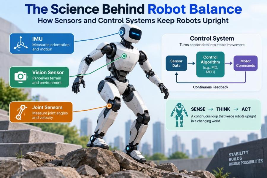
An inertial measurement unit, or IMU, typically combines accelerometers and gyroscopes. It is usually mounted near the robot’s main body, where it can provide rapid information about body motion.
| Sensor element | What it measures | Useful balance information |
|---|---|---|
| Accelerometer | Specific acceleration along axes | Gravity direction when motion is modest; impacts and linear acceleration |
| Gyroscope | Angular velocity | How quickly the body is pitching, rolling, or yawing |
| Magnetometer, when used | Magnetic field direction | Long-term heading reference in suitable environments |
An IMU does not directly announce, “the robot is falling.” Its signals require interpretation, calibration, and combination with other sensors.
📏 Accelerometers Can Be Misleading During Motion
When a robot is standing still, an accelerometer can help infer which direction is down because it senses the effect associated with gravity. During acceleration, however, the sensor also responds to the robot’s changing velocity.
Consider a wheeled balancing robot that suddenly accelerates forward. Its accelerometer may suggest a backward tilt even if its chassis orientation has barely changed. Treating that signal as pure tilt would make the controller issue the wrong correction. This is a classic reason sensor fusion is necessary.
🔄 Gyroscopes Respond Fast but Drift Over Time
Gyroscopes measure rotational speed, making them excellent for detecting a fast pitch or roll change. Integrating angular velocity over time produces an orientation estimate, but small bias errors accumulate. This accumulation is called drift.
A controller that trusted only a gyroscope could gradually believe a level robot is tilted. A controller that trusted only an accelerometer would react poorly to dynamic motion. Combining their complementary strengths is more effective than choosing one.
🧩 Sensor Fusion Builds a Better Orientation Estimate
Sensor fusion combines measurements from multiple sensors with a model of expected motion. A simple complementary filter may use gyroscope data for fast short-term changes and accelerometer data for slower correction. More advanced systems may use Kalman-filter variants or nonlinear observers.
The goal is not to make measurements perfect. It is to make the best practical estimate while accounting for noise, delay, and uncertainty. A well-designed estimator should remain sensible when one sensor becomes temporarily less reliable.
🦿 Encoders Tell the Controller Where the Joints Are
Joint encoders measure motor or joint position, and often velocity can be estimated from changing positions. On a legged robot, encoders reveal knee bend, hip angle, ankle position, and whether the geometry matches the intended posture.
Combined with a kinematic model—the geometric relationship between links and joints—encoder data helps estimate foot location and body configuration. Encoder readings alone are not enough, though: gear backlash, elastic structures, and foot slip can make commanded or measured joint motion differ from actual body motion.
🦶 Contact Sensors Reveal the Ground Interaction
Force sensors in feet, pressure-sensitive elements, motor-current estimates, and contact switches can help determine whether a foot is bearing weight. This information matters when transferring support from one leg to another.
A walking robot that assumes a foot has landed when it is still swinging may shift weight into empty space. Conversely, a foot that catches an obstacle can generate an unexpected force. Reliable contact detection lets the controller revise its plan quickly.
🌍 Vision and Range Sensors Extend Balance Beyond the Body
Cameras, depth sensors, and lidar do not replace an IMU, but they can improve balance by describing what lies ahead. A robot that sees a stair edge, loose gravel, or a gap can select foot placements before it encounters the hazard.
These sensors usually have more processing delay and can be affected by lighting, reflections, or occlusion. For immediate recovery from a shove, fast body sensors dominate. For planning the next several steps, perception becomes increasingly valuable.
⏱️ Timing and Latency Can Decide the Outcome
Balance loops must sense, calculate, communicate, and actuate before an error grows too large. Delay reduces the margin for recovery: by the time a late command reaches a motor, the robot may be leaning farther and moving faster than the controller assumed.
Engineers manage latency by using efficient code, predictable scheduling, rapid low-level motor loops, and estimators designed for real-time operation. They must also account for sensor sampling time and actuator response, not merely processor speed.
🎛️ Feedback Control Turns Measurements into Corrections
A feedback controller compares a desired state with the estimated actual state, then commands an action based on the error. If a robot leans forward beyond its target, the controller may move an ankle, accelerate wheels, shift the hips, or plan a step.
Feedback is essential because real environments cannot be modeled perfectly. It corrects for unplanned pushes, small assembly differences, changing loads, and errors in the robot’s physical model.
📊 PID Control Is Simple but Requires Careful Tuning
A proportional-integral-derivative, or PID, controller is common in motors and simpler balancing systems. The proportional term reacts to current error, the integral term addresses persistent offset, and the derivative term responds to the rate of change.
For example, a two-wheeled robot leaning forward needs a wheel command related to both how far it leans and how rapidly it is falling. Excessive gain can produce oscillation; insufficient gain can make correction sluggish. Integral action can also become problematic if actuator limits cause accumulated error, a condition often called windup.
🔮 Model-Based Control Uses Physics to Look Ahead
More capable legged robots often use model-based control, which incorporates mass, joint geometry, contact forces, and motion constraints. Rather than reacting only to present error, the controller estimates which future actions will keep the system stable.
Model predictive control is one example. It repeatedly evaluates a short future horizon, selects feasible forces or foot motions, applies the first portion of the plan, then solves again after receiving new measurements. It can handle complex constraints, but its value depends on a sufficiently accurate model and timely computation.
🛞 The Inverted Pendulum Is a Useful Starting Model
A balancing robot is frequently approximated as an inverted pendulum: a mass above a pivot that naturally falls away from vertical. A broom balanced on a palm offers the same intuition. The farther it leans, the more urgently the support point must move beneath it.
Real robots are more complicated. They have flexible links, multiple joints, changing contacts, and moving limbs. Still, the inverted-pendulum model provides valuable insight into why fast sensing and corrective movement are fundamental.
👟 Ankles, Hips, and Steps Form a Recovery Hierarchy
Humanoid robots often recover from disturbances in stages. A small error may be corrected at the ankles by shifting pressure under the feet. A larger error may require hip or torso motion to redirect angular momentum.
When those strategies are not enough, the robot must step. Stepping enlarges or relocates the support polygon, but it takes time and requires a safe landing area. A robust controller decides when a smaller correction is no longer physically sufficient and commits to a recovery step early enough.
🌀 Arms and Torso Motion Can Save a Falling Robot
Rapidly swinging an arm changes angular momentum throughout the body. A robot can use this effect to counter a disturbance, much as a person windmills their arms after losing balance.
This is helpful but limited. Arm motion cannot create unlimited correction, and large swings may interfere with nearby people, tools, or payloads. It should be coordinated with foot forces and stepping rather than treated as a substitute for stable locomotion.
🐕 Quadrupeds Gain Contacts but Not Automatic Stability
Four-legged robots can keep three or four feet on the ground, giving them a larger support polygon than a biped in many poses. That often makes slow walking more forgiving.
Yet quadrupeds still face difficult terrain, slipping feet, body oscillations, and rapid gait transitions. At speed, they rely on dynamic balance just as animals do. More legs add options, but also add contact states and coordination decisions.
🛵 Two-Wheeled Robots Balance by Driving Under Themselves
A two-wheeled self-balancing robot has a very small support area. If its body leans forward, it accelerates the wheels forward so the ground contact moves under the center of mass. If it leans backward, it reverses the process.
This creates a counterintuitive rule: to prevent a forward fall, the robot may initially drive forward. It is not escaping the fall; it is repositioning its base fast enough to catch the body.
🧱 Foot Placement Is as Important as Body Posture
A robot may have an excellent torso controller and still fall because it chose a poor foothold. Foot placement determines future support geometry, available friction, and the range of possible recovery actions.
On uneven terrain, planning should consider more than whether a foot fits on a surface. It must consider slope, expected load, edge proximity, clearance for the swing leg, and whether the surface is likely to deform or slide.
🧊 Friction Sets Hard Limits on Ground Forces
To balance, a robot pushes against the ground. That push is limited by friction. On a low-friction surface, a foot may slide before the controller generates the corrective horizontal force it planned.
Controllers can reduce risk by estimating friction, limiting aggressive force commands, widening stance where possible, and adapting gait speed. But no software can overcome a surface that cannot supply the required contact force. Mechanical design and environmental assumptions matter.
📦 Payloads Change the Dynamics Immediately
Picking up a box moves the combined center of mass and changes inertia, which is resistance to changes in rotational motion. A load held far in front of a humanoid can require a substantial posture adjustment even before the robot begins walking.
Practical systems should know, estimate, or detect payload changes. Conservative acceleration limits, load-aware motion planning, and force sensing can reduce surprises. A controller tuned only for an unloaded robot may behave poorly once tools or cargo are added.
🔧 Actuators Need Both Power and Control Authority
Motors, transmissions, and joints must generate enough torque quickly enough to execute the controller’s decision. A perfect algorithm cannot arrest a fall if the actuator saturates, overheats, hits a speed limit, or is slowed by excessive gearbox friction.
Compliance also matters. Series elastic elements can absorb impacts and improve force control, but their flex changes the relationship between motor position and joint position. That behavior must be included in sensing and control design.
📉 Noise, Bias, and Calibration Create Quiet Failure Modes
Balance can degrade gradually rather than fail dramatically. A gyroscope bias, an incorrectly aligned IMU, a drifting encoder zero, or unequal leg geometry can cause a robot to make constant unnecessary corrections.
Calibration establishes the relationship between sensor readings and physical reality. Good practice includes checking coordinate frames, verifying sensor orientation, measuring offsets at rest, and testing repeated motions. Logging data during controlled experiments often exposes errors that are invisible in a single demonstration.
🧪 Simulation Helps, but Reality Still Surprises
Simulation allows engineers to test falls, pushes, sensor noise, and controller settings without repeatedly damaging hardware. It is especially useful for checking whether a planned motion is physically plausible before trying it on a robot.
However, simulated contacts, motor behavior, cable drag, structural flexibility, and surface friction are approximations. The gap between simulation and hardware is often called the sim-to-real gap. Controllers should be validated gradually, with bounded speeds, safety supports, and realistic disturbance tests.
🚧 Safe Testing Requires Designed Failure Modes
Falls are an expected part of balance development, so safe systems need ways to limit their consequences. These may include emergency stops, soft operating zones, fall detection, padded test areas, mechanical tethers during early trials, and motion limits near people.
Fall detection should not simply cut power in every situation; removing torque can sometimes worsen a collapse. The appropriate response depends on the robot’s design, its environment, and its ability to enter a controlled protective pose.
🛠️ A Practical Workflow for Tuning Balance
Balance development is easier when each layer is checked before the next. Trying to tune a high-level walking controller while sensor axes are wrong or motor torque limits are unknown wastes time.
- Confirm mechanical assembly, joint limits, and secure wiring.
- Calibrate IMUs, encoders, and contact sensing; verify coordinate conventions.
- Test each actuator and low-level position, velocity, or torque loop independently.
- Validate the state estimator during stationary and controlled moving tests.
- Begin with supported standing, then modest disturbances, then stepping or locomotion.
- Log commands, estimates, contacts, and temperatures so failures can be diagnosed rather than guessed at.
⚠️ Common Control Mistakes and Their Consequences
Many unstable robots do not fail because the core theory is unknown; they fail because a practical assumption is wrong. Treating delayed data as current, ignoring actuator saturation, or differentiating noisy sensor signals without filtering can all destabilize an otherwise reasonable design.
- Overly aggressive gains: fast corrections become oscillation and repeated foot impacts.
- Ignoring contact uncertainty: the controller applies ground-force logic to a foot that is not reliably planted.
- Using a rigid terrain model: soft mats, carpet, and loose material invalidate assumed contact behavior.
- Testing only calm conditions: a robot that stands in a lab may fail when turning, carrying a load, or receiving a small push.
🔗 Balance Is a Whole-System Property
It is tempting to describe balance as a software feature, but it emerges from the whole robot. Foot shape affects contact stability. Battery location affects center of mass. Transmission selection affects response time. Sensor placement affects vibration sensitivity. Software architecture affects delay.
The strongest designs make these choices together. If a mechanical limitation cannot be removed, the controller should know about it. If a controller demands a motion frequently, the hardware must be capable of delivering it repeatedly and safely.
🌱 What Better Balance Enables
Reliable balance expands where robots can work. It supports inspection in cluttered facilities, assistance devices that move with people, mobile manipulation in warehouses, machines that cross irregular outdoor terrain, and research platforms that study locomotion.
It also improves efficiency. A robot that predicts and absorbs a small disturbance can continue its task; one that must stop, brace, or be reset loses time. The goal is not human-like motion for its own sake, but dependable motion suited to a real job.
🧭 The Core Principle: Sense, Estimate, Predict, Act
Every successful balancing system follows a continuous cycle. Sensors observe motion and contact. Estimation converts imperfect readings into a coherent body state. A controller predicts the consequence of available actions. Actuators then apply forces or reposition contacts, and the loop begins again.
The details differ between a wheeled robot, quadruped, and humanoid, but the principle remains: stability comes from matching physical capability with fast, trustworthy information and well-timed correction. No single sensor or algorithm can carry the entire task.
Robot balance is the disciplined coordination of mechanics, sensing, estimation, and control—not a trick that one component can solve alone. As robots move into more varied environments, that coordination will remain one of the clearest measures of capable engineering. 🦾⚖️🤖