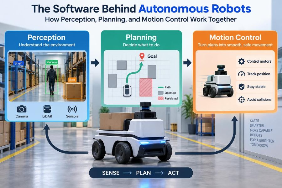

A warehouse robot rolls toward a shelf, pauses as a person crosses its route, turns around a misplaced box, and places a tote at a packing station. From the outside, the behavior can look almost obvious: see the obstacle, choose another path, keep moving.
Inside the machine, that single maneuver is a tightly coordinated software problem. Cameras and sensors produce incomplete, noisy measurements. Algorithms turn those measurements into an estimate of the surroundings. A planner decides what to do next, while low-level control software makes motors carry out that decision without slipping, overshooting, or colliding.
The same pattern appears in robot vacuums, agricultural machines, surgical assistants, drones, autonomous mobile robots, and self-driving research platforms. Their bodies differ, but their software must repeatedly answer three questions: What is around me? What should I do? How do I move safely?
Understanding the connections between perception, planning, and motion control makes autonomous robotics less mysterious. It also explains why a robot can perform well in a demonstration yet struggle in a cluttered room, a dim warehouse, or a changing outdoor environment.
🤖 Autonomy Is a Closed-Loop System
An autonomous robot does not simply run a route stored in memory. It operates in a closed loop: it senses the world, estimates its state, chooses an action, executes it, and senses again.
This loop distinguishes autonomy from a timer-driven machine. A timed conveyor can repeat a fixed pattern. A mobile robot must adapt when a wheel slips, a doorway is blocked, or its location estimate becomes uncertain.
🧠 The Three-Layer View
Perception, planning, and control are useful names for three major responsibilities. Perception converts sensor signals into meaningful estimates. Planning selects goals and routes. Control translates desired movement into actuator commands.
The boundaries are not perfectly rigid. A planner must account for what sensors can reliably detect, and a controller may use sensor feedback directly. Still, separating the roles helps engineers diagnose failures instead of treating “the robot software” as one opaque system.
| Layer | Primary question | Typical output |
|---|---|---|
| Perception | What is happening? | Robot pose, obstacles, object positions |
| Planning | What should happen next? | Task sequence, route, trajectory |
| Control | How should the robot move now? | Motor torque, wheel speed, joint command |
📡 Sensors Are Measurements, Not Understanding
A sensor does not report “there is a chair.” A camera provides pixels, a lidar provides distance returns, an encoder reports shaft rotation, and an inertial measurement unit reports acceleration and angular rate.
Every measurement has limitations. Cameras depend on lighting and can confuse visually similar surfaces. Lidar may have difficulty with some reflective, transparent, or very dark materials. Wheel encoders accumulate error when wheels slip.
Good robotics software begins by respecting this gap between a signal and an interpretation.
👁️ Perception Turns Data Into Meaning
Perception is the process of extracting useful state from raw sensor data. Depending on the job, it may detect people, estimate the location of a pallet, identify a grasp point, recognize terrain, or measure free space.
For a delivery robot, free-space detection may matter more than naming every object. For a sorting arm, identifying an item’s orientation may be essential. Perception should be designed around the decision the robot must make, not around a desire to recognize everything.
🧭 Localization Answers “Where Am I?”
Planning is only meaningful if the robot knows its position and orientation, collectively called its pose. A robot that is wrong about its location may follow an otherwise excellent route straight into the wrong aisle.
Localization can use wheel odometry, landmarks, satellite positioning outdoors, lidar maps, camera features, or radio-based signals. In practice, systems often combine several sources because each fails differently.
🗺️ Mapping and Localization Often Support Each Other
When a robot builds a map while estimating its own pose, the problem is often called simultaneous localization and mapping, or SLAM. It is especially useful where a detailed map is unavailable.
Imagine a robot entering an unfamiliar office. As it observes walls, corners, and furniture, it uses those observations to refine its position. Better position estimates also make the developing map more consistent. This circular dependency is why SLAM is challenging.
🧩 Sensor Fusion Reduces Blind Spots
Sensor fusion combines measurements so that one source can compensate for another. An IMU reacts quickly to motion but drifts over time; wheel encoders describe travel but can slip; a camera can identify visual landmarks but may fail in low light.
Fusion does not magically remove uncertainty. It provides a more useful estimate when assumptions are reasonable and sensor timing, calibration, and coordinate frames are handled carefully.
🎯 Detection Is Not the Same as Tracking
Detecting a pedestrian in one camera frame is different from tracking that pedestrian over several seconds. Tracking estimates where a moving object has been and where it may go next.
This matters when paths intersect. A robot should not only ask whether a person occupies a point now, but also whether the person is likely to enter its path before it can stop or turn.
🌫️ Uncertainty Must Travel Through the System
Sensor estimates are never perfectly certain. A robust system represents uncertainty explicitly or behaves conservatively when confidence is low. If the robot is unsure whether an area is clear, the correct response may be to slow down, seek another view, or stop.
A common design mistake is passing a single precise-looking position from perception to planning while hiding how unreliable it is. That can make plans appear safe in software even when the underlying evidence is weak.
🧱 The World Model Is the Robot’s Working Memory
Perception outputs are organized into a world model: a structured, temporary representation of the robot, fixed features, moving agents, permitted zones, and obstacles. It may include a grid map, a geometric scene, labeled objects, or several forms at once.
For navigation, an occupancy grid is common. Space is divided into cells, each representing whether it is likely free, occupied, or unknown. The planner can then reason about routes without processing every raw sensor reading again.
🧹 Static Maps Need Dynamic Updates
A prebuilt map can show walls and shelving, but real environments change. Doors open, carts move, boxes appear, and people choose unpredictable paths.
Autonomous robots usually combine a relatively stable map with a local, frequently updated obstacle layer. Treating the whole environment as static creates obvious hazards; treating everything as newly discovered wastes useful prior knowledge.
🏁 Task Planning Chooses the Next Meaningful Action
Planning begins above navigation. A task planner decides actions such as “collect the tote,” “go to station three,” “wait for access,” or “return to charge.” It handles ordering, preconditions, and recovery logic.
In a warehouse, the shortest path to a shelf is irrelevant if the robot has not yet selected the correct tote or if the shelf is inaccessible. Task planning connects business-level objectives to physical behavior.
🛣️ Global Planning Finds a Route Through Space
Once a destination is selected, a global planner finds a route through the known map. Graph-search methods can represent corridors, intersections, and free cells as connected choices, then seek a route with low cost.
Cost need not mean distance alone. A route may be penalized for narrow clearances, restricted areas, steep ground, congestion, or low localization confidence. The “best” route depends on the robot’s actual operating priorities.
⚡ Local Planning Handles What Changed
A global route cannot anticipate a person stepping into the aisle seconds later. A local planner repeatedly chooses short-horizon motion that respects nearby obstacles, current velocity, and the robot’s physical limits.
Think of global planning as selecting a road trip and local planning as steering around a temporary lane closure. The local layer should keep the robot safe without abandoning the larger mission whenever a small disruption occurs.
📈 A Path Is Not Yet a Drivable Trajectory
A path describes where the robot should go. A trajectory adds time: position, velocity, and often acceleration at successive moments. This distinction matters because a robot cannot instantaneously change direction or speed.
A smooth curve that is geometrically collision-free may still be impossible for a forklift-like vehicle with a limited turning radius. Likewise, an arm may reach a pose only by exceeding joint-speed limits.
⚙️ Kinematics Connect Motion to Geometry
Kinematics describes geometric motion without focusing on forces. Forward kinematics computes where a robot’s tool or wheel assembly is from joint positions. Inverse kinematics finds joint configurations that achieve a desired tool pose.
A six-joint arm, for example, may have multiple ways to place its gripper at one point. The planner must choose a configuration that avoids self-collision, respects joint limits, and leaves room for the next movement.
🏋️ Dynamics Add Mass, Force, and Momentum
Dynamics matters when forces cannot be ignored. A loaded mobile robot takes longer to stop than an empty one. A fast arm can flex, vibrate, or overload a motor if commanded too aggressively.
Planning and control that account for mass, friction, gravity, and actuator capability generally produce more reliable movement. Simplified models can still work, but their operating range must be tested honestly.
🎛️ Motion Control Closes the Physical Loop
Motion control compares the desired state with the measured state and commands actuators to reduce the difference. On a wheeled robot, it may regulate wheel velocities. On an arm, it may regulate joint positions, velocities, or torques.
Without feedback, small disturbances accumulate. A wheel rolls over a cable, a battery voltage changes, or a payload shifts. Feedback lets the robot correct rather than blindly assume the last command succeeded.
🔁 Why Feedback Controllers Matter
A familiar example is a proportional-integral-derivative, or PID, controller. It responds to current error, accumulated error, and the rate at which error is changing. Properly tuned PID control is widely useful because it is understandable and computationally light.
It is not a universal answer. Complex systems with strong coupling, changing loads, or strict future constraints may use more model-based approaches. Whatever method is chosen, tuning must be validated on the real machine, not only in simulation.
⏱️ Timing Is Part of Correctness
Robotics components operate at different rates. Motor control may run very frequently, obstacle updates may arrive less often, and task decisions may occur only when an event changes. Data that is correct but late can be unsafe.
Timestamping, synchronization, and bounded communication delays are therefore engineering requirements, not implementation details. If a controller acts on an old obstacle position while the robot is moving quickly, its response can be inappropriate.
🧮 Coordinate Frames Prevent Expensive Confusion
Robots reason in many coordinate frames: camera frame, lidar frame, robot base frame, arm tool frame, map frame, and world frame. A transform describes how a point or orientation in one frame relates to another.
A misplaced transform can make a correctly detected object appear shifted, rotated, or behind the robot. Calibration errors are especially troublesome because the failure may look like poor perception or bad control rather than a geometric mismatch.
🛑 Safety Is an Architecture, Not a Single Feature
Collision avoidance software is valuable, but it should not be the sole protection. Practical systems combine speed limits, protective stopping behavior, emergency-stop circuits, operational boundaries, fault detection, and human-aware procedures.
The appropriate safeguards depend on the robot, environment, applicable requirements, and hazards. A small educational rover and an industrial manipulator carrying a heavy payload demand very different risk assessments.
🧯 Fallback Behavior Makes Failures Manageable
Every layer can fail: a camera can be blocked, localization can drift, a planner can find no valid route, or an actuator can report a fault. Good autonomy defines what the robot does next.
- Reduce speed when localization confidence degrades.
- Stop when a required sensor becomes unavailable.
- Request help when a route remains blocked.
- Move to a safe pose after an arm-planning failure.
- Record diagnostic data for later analysis.
A controlled stop is often a successful safety response, not evidence that the system has “given up.”
🧪 Simulation Speeds Learning but Cannot Replace Reality
Simulation is useful for testing routes, training perception models, evaluating edge cases, and finding obvious software defects before hardware is exposed. It also makes repeatable experiments easier.
Yet simulators approximate sensors, surfaces, lighting, contact, latency, and human behavior. The difference between simulation and deployment is often called the reality gap. Field testing remains necessary, especially for safety-critical behavior.
📊 Logging Turns Robot Behavior Into Evidence
When a robot hesitates or collides, video alone rarely answers why. Engineers need synchronized logs of sensor inputs, pose estimates, planner decisions, control commands, faults, and timing information.
Useful logs support replay: the ability to feed recorded data through updated software and compare behavior. This turns debugging from guesswork into a testable investigation.
🧱 Interfaces Keep Complexity Contained
Autonomy software becomes fragile when every module directly reaches into every other module. Clear interfaces define what perception publishes, what planning may assume, and what control guarantees.
For example, a planner may receive an obstacle map with timestamps and confidence information rather than raw camera images. That separation allows teams to improve a detector without rewriting route selection.
🔄 Recovery Is Part of Normal Operation
Real robots encounter ambiguous situations: a route stays blocked, a grasp fails, a door is closed, or a map no longer matches the room. Recovery logic decides whether to retry, re-observe, choose an alternative, notify an operator, or end the task safely.
Designing only for the happy path creates brittle autonomy. A robot becomes useful when it can recognize that a plan no longer applies and respond in a bounded, understandable way.
🧑🤝🧑 Humans Change the Planning Problem
People do not move like predictable obstacles. They stop, reverse, carry large items, and interpret a robot’s behavior socially. A machine that cuts closely in front of someone may be collision-free yet feel unsafe or rude.
Human-aware navigation often favors larger personal space, readable speed changes, and cautious behavior near crossings. These choices may reduce theoretical throughput, but can improve acceptance and practical safety.
🔌 Compute, Power, and Communication Set Real Limits
Advanced algorithms require processing power, memory, electrical energy, and reliable data paths. A perception model that works on a powerful workstation may be too slow or power-hungry for an onboard computer.
Cloud connectivity can help with fleet coordination or data analysis, but a moving robot should not depend on a network response for immediate collision avoidance. Time-critical safety behavior belongs close to the machine.
🧰 Common Integration Mistakes
Many autonomy problems are integration problems rather than failures of a single algorithm. Teams may tune control before calibrating sensors, use maps with inconsistent frames, or test each component alone without testing delays between them.
- Assuming detected objects have exact positions.
- Planning motions the hardware cannot physically execute.
- Ignoring battery state, payload changes, or wheel wear.
- Testing only uncluttered, well-lit scenarios.
- Adding complexity before establishing reliable stop behavior.
A simpler pipeline with measured assumptions is often more dependable than an impressive stack with poorly understood interactions.
🛠️ A Practical Development Sequence
For students and teams building a first autonomous platform, begin with observability and basic safety. Confirm that sensor timestamps, frames, actuator directions, and emergency behavior are correct before pursuing sophisticated autonomy.
- Characterize sensors and calibrate their mounting.
- Build reliable state estimation and logging.
- Demonstrate slow, closed-loop motion in a controlled area.
- Add mapping, local obstacle handling, and simple goals.
- Expand scenarios one variable at a time: speed, clutter, lighting, or payload.
- Define failure criteria and recovery actions before broader deployment.
This sequence limits the number of unknowns when something goes wrong.
🔮 Learning Methods Are Tools, Not Complete Architectures
Machine learning can strengthen perception, estimate grasp quality, predict motion, or help tune policies from data. It is particularly useful where hand-written rules struggle with visual variation.
However, learned components still need clear inputs, validation, monitoring, and safe interfaces with planning and control. A highly capable detector cannot compensate for a planner that ignores braking distance, and a learned policy still requires operational limits.
🧭 The Core Principle: Coordinate Decisions Across Layers
The essential lesson is not that every robot needs the same sensors or algorithms. It is that perception, planning, and control must share compatible assumptions about space, time, uncertainty, and physical capability.
Perception should report what is known and how confidently it is known. Planning should choose actions that are safe and feasible. Control should execute those actions while continuously correcting for the real world. Safety and recovery logic must remain active across the entire chain.
A robot is autonomous not because it contains one clever algorithm, but because these layers form a disciplined feedback system that can observe, decide, act, and adapt.
Reliable autonomous robots emerge when perception, planning, and motion control are engineered as one connected loop rather than three separate features. That systems mindset is as valuable in a student rover as it is in an industrial fleet. 🦾🧭🤖