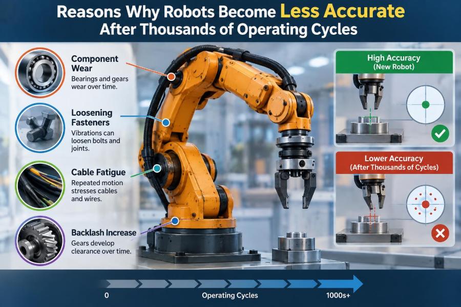

A robot can place a part perfectly for weeks, then begin missing a fixture by a fraction of a millimeter. Nothing may look broken. The program has not changed, the part drawing is the same, and the robot may still complete every cycle.
That small change matters. In a welding cell, it can shift a seam. In dispensing, it can put adhesive beside the intended path. In machine tending, it can make insertion unreliable or cause a gripper to contact a clamp.
Robots are often described as repeatable, and good industrial robots are remarkably repeatable. But repeatability is not the same as accuracy, and neither property is permanent without the mechanical condition, environment, tooling, and calibration being controlled.
Thousands of cycles expose a robot system to tiny changes that add up. Understanding where those changes come from helps engineers diagnose drift before it becomes scrap, downtime, or a safety concern.
🎯 Accuracy and Repeatability Are Different Measurements
Accuracy is how close the robot’s actual tool position is to the commanded or intended position. Repeatability is how consistently it returns to the same actual position when it repeats the same command.
A robot can be highly repeatable but inaccurate. For example, it may return to a point 0.4 mm away from its taught location almost every time. That is often manageable if the process is retaught or calibrated, but it becomes a problem when the offset changes with posture, load, or time.
📉 Why Cycle Count Reveals Hidden Problems
One operating cycle creates a small amount of motion, force, heat, vibration, and electrical activity. Most effects are negligible in isolation. Repeated over long production runs, however, friction changes surfaces, fasteners settle, cables flex, and temperatures vary.
Cycle count is therefore a useful maintenance signal, not a direct measure of robot health. A lightly loaded robot moving smoothly in a clean room can age very differently from one accelerating a heavy weld gun near its payload limit in a dusty cell.
⚙️ Joint Gearbox Wear Creates Lost Motion
Robot joints commonly use compact, high-ratio gear reducers. Over time, contact surfaces can wear, lubrication can degrade, and clearances can increase. The result is often called backlash: a small amount of movement at the joint before torque is transmitted in the opposite direction.
Because several joints contribute to tool-center-point position, a tiny clearance at each joint can become noticeable at the end effector. The effect may be strongest when the robot approaches a point from alternating directions.
🔄 Backlash Often Looks Like Direction-Dependent Error
A useful diagnostic clue is this: the robot reaches a point correctly when approaching from the left, but differently when approaching from the right. This does not automatically prove gearbox wear, but it strongly suggests that friction, clearance, or compliance is involved.
Testing only one approach path can hide the issue. A meaningful check sends the robot to the same reference feature from multiple directions and records the error at the actual tool tip, not just in joint-position data.
🛢️ Lubrication Does More Than Reduce Noise
Grease and oil separate moving surfaces, carry heat, and help protect components from contamination. Incorrect lubricant type, inadequate quantity, aged lubricant, or an undetected leak can increase friction and accelerate wear.
Changing lubricant is not a universal cure. A joint already damaged by wear may still show positional error after service. Follow the robot manufacturer’s specified intervals, materials, and procedures; unsuitable grease can be as harmful as neglected grease.
🌡️ Thermal Expansion Changes Geometry
Metals expand when heated. A robot arm, tool flange, fixture, workpiece, and supporting structure do not necessarily warm at the same rate or to the same temperature. This changes the geometry that a calibrated program assumes.
A robot may be accurate during a cold verification and offset after an hour of fast production. Motors, gearboxes, nearby welding, and ambient temperature can all contribute. The effect is usually gradual, which makes it easy to mistake for programming drift.
🔥 Motor Heating Can Alter Dynamic Behavior
High torque and frequent acceleration heat servo motors and drives. Control systems compensate for many normal effects, but sustained temperature changes can alter friction, torque availability, and the behavior of a heavily loaded axis.
The practical question is whether errors correlate with duty cycle. If a cell is stable after warm-up but poor during rapid starts, stops, or extended high-speed operation, investigate thermal loading alongside mechanical alignment.
📐 Encoder Problems Affect the Robot’s Sense of Position
Encoders provide feedback about joint position. If an encoder, its connection, or associated reference data is compromised, the controller may no longer have a trustworthy relationship between reported joint angle and physical joint angle.
Modern systems usually detect serious feedback faults and stop rather than silently continue. Still, intermittent connections, reference-loss events, incorrect mastering, or damage after maintenance can create subtle position concerns that require manufacturer-approved checks.
🧭 Mastering and Zero References Can Shift After Service
Mastering establishes the relationship between each joint’s encoder reading and its mechanical zero position. Robot kinematics depend on that reference. If mastering is wrong, every programmed location may be displaced.
This is especially relevant after motor replacement, brake work, collision recovery, controller battery issues, or any procedure that requires recalibration. A robot can remain repeatable after incorrect mastering while being wrong everywhere in a posture-dependent pattern.
🧮 Small Joint Errors Combine at the Tool Center Point
The tool center point, often shortened to TCP, is the point the robot program treats as the working tip: a gripper jaw reference, torch tip, dispensing nozzle, or screwdriver bit. Its position is calculated from all joint angles, arm dimensions, flange geometry, and tool data.
Errors do not simply add in a neat straight line. Their final direction and magnitude depend on the robot’s pose. That is why a robot may pass a check near one location yet miss a feature elsewhere in its workspace.
🧰 Tool Center Point Calibration Can Slowly Become Wrong
Tooling is not permanent geometry. A nozzle can be replaced, a gripper finger can bend, a torch neck can be bumped, or a tool can be reassembled with a small rotational change. Any of these can invalidate a previously correct TCP.
Consider a dispensing tool whose nozzle tip is 1 mm longer after replacement. The robot may faithfully move the old TCP through the programmed path while the real nozzle sits 1 mm lower. The robot is not necessarily at fault; its model of the tool is outdated.
🧲 End-Effectors Lose Stiffness and Alignment
Grippers, weld guns, compliance devices, spindle holders, and quick-change couplers have their own bearings, pivots, fasteners, and wear surfaces. Their motion can introduce error even when the robot arm itself is healthy.
Inspect the complete load path from robot flange to process point. A loose bracket or worn gripper pivot often causes errors that appear only when the tool contacts a part, grips a load, or applies process force.
🏋️ Payload Changes Increase Deflection
Every structure bends slightly under load. Robot manufacturers publish payload and wrist-moment limits because a tool’s mass and center of gravity affect both safety and positioning performance.
An added camera, longer bracket, larger cable bundle, or different part can move the center of gravity farther from the wrist. Even if total mass remains below the rated payload, the changed moment can increase deflection and make fast moves less stable.
🏃 Speed and Acceleration Magnify Flexible-System Effects
At low speed, a flexible arm-and-tool system may settle close to its target. At high acceleration, inertia can bend brackets, excite vibration, and produce overshoot or oscillation at the TCP.
This is not always a permanent loss of accuracy. It may be a dynamic error, meaning the position is wrong while the system is moving or before it has settled. Reducing acceleration, improving tool stiffness, or adding an appropriate settling delay can reveal the cause.
📳 Vibration Loosens More Than Fasteners
Repeated vibration can affect bolts, locating pins, connector retention, cable supports, fixtures, and sensitive process hardware. It can also make a vision camera’s mounting angle drift slightly over time.
Torque checks should be performed using approved values and procedures, not by indiscriminately tightening every bolt. Over-tightening can damage threads or distort a component. The goal is controlled mechanical integrity, not maximum force.
🧱 The Robot Base and Pedestal Must Stay Rigid
A robot is only as stable as the surface supporting it. A loose anchor, cracked grout, flexible platform, or pedestal that shifts under load changes the base frame from which all robot positions are calculated.
Base movement can be deceptive because it may vary with robot pose. An error observed at full reach but not near the base may come from pedestal compliance rather than an internal joint problem.
🗜️ Fixtures and Part Location Can Be the Real Source
When a robot misses its target, teams often inspect the robot first. Yet a worn locating pin, accumulated chips, warped nest, weak clamp, or inconsistent incoming part can move the workpiece instead.
Separate robot position from part position. A fixed reference artifact or calibrated target can check the robot independently, while fixture gauges and part-location checks determine whether the process reference has moved.
👁️ Vision Systems Can Drift Without the Arm Moving
Robot guidance systems depend on camera calibration, lens focus, lighting, mounting rigidity, and coordinate transformations between camera, robot, and workpiece frames. A camera bracket shift or lens disturbance can change calculated pick positions.
Dirty lenses and inconsistent lighting may not cause a constant offset; they can create variable measurement error. This distinction matters: a stable offset suggests calibration or mounting, while scatter suggests image quality, detection, or part-presentation issues.
🔌 Cable Dress Packs Add Force and Restrict Motion
Hoses and cables bend every cycle. If routing is poor, a dress pack can tug on the wrist, catch on equipment, stiffen at certain joint angles, or gradually fatigue internally.
The effect is often pose-specific. Watch the robot slowly through the problematic region and look for cable tension, rubbing, snagging, or a cable bundle that changes the natural resting position of the tool.
💥 Collisions Can Cause Damage Too Small to See
A collision may bend a tool, shift a bracket, damage a gearbox, disturb a camera, or alter a fixture before leaving obvious external evidence. A robot that resumes operation after a fault reset is not automatically verified as accurate.
After any significant impact, inspect the affected equipment and run a defined recovery check: TCP verification, reference-point test, tool inspection, fixture confirmation, and, where required, manufacturer-supported mechanical evaluation.
⚡ Brakes and Servo Control Need Context
Joint brakes primarily hold axes when servo power is removed; they are not normally responsible for precise motion during powered operation. Brake wear can nevertheless matter during power loss, vertical-axis service, or recovery events.
Servo tuning, drive faults, and unstable control behavior can also affect path quality. These issues should be evaluated with controller diagnostics and qualified personnel, because changing control parameters without a structured test can create unsafe or worse-performing motion.
🧪 Process Forces Can Push the Robot Off Path
Some tasks are not free-space motions. Drilling, polishing, deburring, routing, sealing against a surface, and force-controlled insertion apply external loads. The tool and arm deflect under those loads, especially near full reach.
A programmed path may be geometrically correct before contact but inaccurate during the process. Force sensing, compliant tooling, feed-rate control, and process-specific calibration can help, but they must be selected for the application rather than treated as generic upgrades.
🌫️ Contamination Changes Mechanical and Optical Conditions
Dust, abrasive particles, coolant mist, weld spatter, oil, and moisture can degrade joints, covers, connectors, sensors, and camera windows. Contamination can also build up on a nozzle or gripper, physically changing the process point.
The right response depends on the environment: protective covers, better enclosure design, air management, routine cleaning, and suitable robot protection ratings may all be relevant. Cleaning itself should avoid forcing contaminants deeper into seals or optics.
📊 Trend Data Is Better Than Waiting for a Failure
A periodic reference check turns accuracy into a measurable trend. It might use a precision pin, touch probe, dial indicator, laser tracker, calibrated vision target, or a purpose-built fixture, depending on required tolerance.
Record the robot pose, approach direction, tool, load, temperature condition, measured deviation, and recent maintenance. A single failed check tells you there is a problem; a history of checks can show whether it is gradual, abrupt, thermal, or tied to a specific configuration.
🔍 Diagnose the Pattern Before Recalibrating
Recalibration can hide valuable evidence. First ask whether the error is constant, direction-dependent, pose-dependent, load-dependent, temperature-dependent, random, or tied to one tool.
| Observed pattern | Possible contributors | Useful first check |
|---|---|---|
| Same offset at many points | Base frame, user frame, TCP, mastering | Verify coordinate data and a fixed reference |
| Different result by approach direction | Backlash, friction, compliance | Repeat tests from opposing paths |
| Error grows with reach or payload | Deflection, pedestal or tool stiffness | Compare poses and loads |
| Error after warm-up | Thermal effects, duty-cycle loading | Log cold and hot measurements |
| Inconsistent scatter | Vision, fixture, contamination, loose components | Check measurement and part location |
🧭 Use a Controlled Reference Instead of a Convenient Part
A production part is often a poor diagnostic standard because it has its own dimensional variation and locating uncertainty. A controlled reference feature makes it easier to determine whether the robot system or the workpiece process is changing.
For tight-tolerance work, use a measurement method whose uncertainty is appropriate for the tolerance being investigated. A rough visual check cannot distinguish a subtle robot drift from normal observation error.
🛠️ Preventive Maintenance Must Match the Application
A calendar-only maintenance plan misses how robots actually age. Build intervals around cycle count, payload, duty cycle, environment, process forces, collision history, and manufacturer guidance.
- Inspect tooling, fasteners, cable routing, and fixtures at planned intervals.
- Verify TCPs after tool changes, impacts, or mechanical adjustment.
- Monitor lubricant condition and service joints according to approved instructions.
- Trend a repeatable accuracy reference under representative production conditions.
- Train operators to report new sounds, vibration, snagging, and process variation early.
🚫 Common Fixes That Mask the Underlying Cause
Retouching points may restore production temporarily, but repeated retouching can conceal wear or a shifting fixture. The next shift may need another correction, and the process gradually becomes dependent on tribal knowledge.
Other weak responses include raising speed to recover lost throughput, changing offsets without recording them, and blaming “robot drift” before checking the tool and fixture. Corrections should be documented, reversible, and tied to an identified hypothesis.
🧑🔧 When to Call the Robot Manufacturer or Integrator
Escalate when there is suspected internal axis damage, abnormal noise, recurring encoder or servo alarms, mastering uncertainty, collision damage, unexplained position variation, or an accuracy requirement beyond in-house measurement capability.
Integrators are especially valuable when the issue involves the full cell: robot, tooling, vision, safety equipment, PLC logic, fixtures, and process parameters. A system-level fault rarely yields to a single-component assumption.
🛡️ Accuracy Is Also a Safety and Quality Issue
Position error is not only a quality concern. A shifted path can bring a tool too close to guards, clamps, people during teaching, or other equipment. Any change to robot calibration, tool data, payload, or operating path should be managed under the site’s established safety procedures.
Do not perform live robot troubleshooting casually. Lockout practices, safe-speed operation, restricted-space rules, and authorized personnel requirements vary by workplace and robot system.
🧠 The Core Principle: A Robot Is a Complete System
Robots become less accurate after many cycles because their real-world system no longer matches the mathematical model used by the controller. Wear, heat, calibration shifts, flexible tooling, cable forces, moving fixtures, and changing measurements can all create that mismatch.
The most reliable response is not to assume one cause. Measure a known reference, classify the error pattern, inspect the entire chain from base to process point, and correct the verified source. This approach protects both production quality and the useful life of the equipment.
Long-term robot accuracy comes from managing the whole system—not merely retouching the robot program when a process begins to miss. 🦾📏🔧