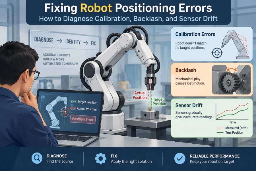

A robot can run the same programmed path all morning and then begin missing a fixture by a millimeter after lunch. A pick-and-place arm may place parts progressively farther from the target. A mobile robot may report that it is at a docking station while its charger contacts are visibly misaligned.
These are not merely “accuracy problems.” Positioning errors have different signatures, different causes, and very different fixes. Adjusting a calibration value may temporarily hide a loose gearbox; replacing a sensor may do nothing if the coordinate frame is wrong.
For students, diagnosing these faults turns abstract kinematics into a practical skill. For working professionals, it protects cycle time, quality, tooling, and—when a robot works near people—safe operation.
The useful question is not simply, “How far off is the robot?” It is: when, where, and in which direction does the error appear? Those observations narrow the problem from a huge list of possible failures into a testable diagnosis.
🎯 Start by Defining the Positioning Problem
“Position” can mean several things: a joint angle, tool-center-point location, camera-measured part location, or a mobile robot’s pose on a map. Define the intended reference and the measured reference before troubleshooting.
Record the error as a vector when possible: X, Y, Z, and orientation. “Off by 2 mm” is less informative than “consistently 2 mm in positive X, with correct Z and yaw.”
📏 Separate Accuracy, Repeatability, and Resolution
Accuracy is closeness to the commanded or true location. Repeatability is how consistently the robot returns to the same location. Resolution is the smallest command or measurement increment the system can distinguish.
A robot can be highly repeatable but inaccurate: it returns to the wrong point every time. That usually suggests calibration, frame, or geometric-model error. A robot that lands in a different place on repeated attempts has a repeatability problem, often involving backlash, compliance, noise, or intermittent sensing.
🧭 Establish a Trustworthy Measurement Reference
Do not diagnose a robot with a measuring method that moves, flexes, or has its own uncertain origin. Secure gauges, target boards, fixtures, and reference artifacts to stable structures.
Use a measurement tool appropriate to the tolerance. A camera can reveal trends quickly, while a dial indicator, touch probe, laser tracker, or precision fixture may be needed for finer work. The instrument’s uncertainty must be comfortably smaller than the error being investigated.
🗂️ Capture the Conditions, Not Just the Result
A useful fault record includes robot program, payload, tool, speed, approach direction, joint configuration, temperature state, and error measurement. This context often exposes patterns hidden by a single pass/fail result.
- Does the error grow after a warm-up period?
- Does it occur only with a heavy payload?
- Does approaching from the opposite direction change the result?
- Is one workstation wrong while other points are correct?
These questions divide likely mechanical, thermal, sensing, and coordinate-system causes.
🧪 Run a Simple Repeatability Test First
Command the robot to approach a fixed target from the same path many times. Measure each final position without changing the setup. A tight cluster displaced from target points toward systematic error; a broad cluster points toward variation.
Then repeat the test with reversed approach direction. This one change is especially revealing for backlash. Keep safety limits active, and never place hands or improvised targets inside an operating envelope without following the cell’s approved lockout and teaching procedures.
🗺️ Understand the Coordinate-Frame Chain
Most industrial robots transform a point through several coordinate frames: joint coordinates, robot base, flange, tool center point (TCP), workobject or user frame, and sometimes camera frame. Each transform depends on values being correct.
An error in a base frame shifts every task in that frame. An incorrect TCP causes errors that change with wrist orientation. A bad work frame may make a robot accurate relative to itself but wrong relative to the fixture.
🔧 Verify the Tool Center Point
The TCP is the effective point on the tool used for path planning: perhaps a gripper fingertip, weld-wire tip, or dispensing nozzle. If its offset from the flange is wrong, rotating the wrist moves the real tool tip away from the expected point.
Perform the controller’s approved TCP calibration procedure using a stable reference point and multiple tool orientations. Reject results that require awkward, poorly observed poses or that vary substantially between repeated calibrations.
📐 Check Workobject and Base Frames
A workobject frame tells the robot where the fixture exists in space. It can become wrong after fixture replacement, collision, floor work, robot relocation, or an operator selecting the wrong program frame.
Check known fixture features at separated locations, not only one origin point. A frame can appear correct at its origin yet have the wrong orientation, producing errors that grow across the work area.
🔄 Recognize a Calibration Error Pattern
Calibration-related errors are usually repeatable and structured. The robot may miss every location by a similar translation, rotate paths around an incorrect frame origin, or show increasing deviation farther from a reference point.
Before recalibrating, confirm that the underlying mechanics are stable. Calibrating around a worn joint can make a short test look better while creating inconsistent results during production.
⚙️ What Backlash Actually Is
Backlash is lost motion between mechanical elements when direction reverses. Gear teeth, harmonic drives, belts, couplings, ball screws, and bearings can all contribute. The motor encoder may report motion before the output link has fully taken up the clearance.
Think of turning a steering wheel slightly before the wheels respond. The system is not necessarily unable to reach position; it has an uncertain relationship between motor movement and output position around a reversal.
↔️ Test for Directional Hysteresis
Approach the same target from opposite directions at low, controlled speed. If the final measurement shifts according to the approach direction, the difference is called hysteresis and backlash is a leading suspect.
Test more than one joint pose. A problem localized to a particular joint can appear stronger where that joint contributes more to the tool motion. Controller logs may also show following error, but a normal log does not rule out clearance downstream of the encoder.
🪢 Inspect Mechanical Sources of Lost Motion
With the robot safely powered down and isolated according to its procedures, trained personnel can inspect likely interfaces: mounting bolts, tool adapters, couplings, belts, transmission components, and fixture clamps. Look for looseness, damaged fasteners, unusual wear debris, or movement under a controlled load.
Do not attempt to “feel” backlash by forcing a powered robot. Mechanical inspection belongs within manufacturer guidance and facility safety rules, particularly for high-payload arms and vertical axes.
📦 Include Payload and Tool Compliance
Not every direction-dependent error is gearbox backlash. A long, flexible tool, soft gripper fingers, a bending fixture, or a heavy payload can deflect differently during acceleration, deceleration, and contact.
Compare results with and without the production payload where safe and meaningful. If the error changes sharply with load or acceleration but not with slow static positioning, compliance or dynamic deflection may be more relevant than calibration.
🏎️ Compare Slow Motion with Production Speed
A robot that positions well in teach mode but misses at production speed may have dynamic effects: servo tuning limits, vibration, cable drag, payload-model error, or insufficient settling time. High speed can expose a flexible structure that appears rigid in a static check.
Reduce speed and acceleration methodically rather than making random changes. If the error decreases, identify which motion phase causes it and restore performance only after the mechanical or control cause is understood.
🌡️ Identify Thermal Drift
Thermal drift is gradual position change caused by warming motors, gearboxes, structures, sensors, electronics, or the surrounding environment. Materials expand at different rates, and sensors can change offset with temperature.
The signature is often time-dependent: a cold robot is accurate, then slowly shifts as it runs. Log error against elapsed run time and, where available, component temperature. Avoid assuming temperature is the cause merely because the fault appears later in a shift.
📡 Understand Sensor Drift
Sensor drift is a gradual change in a sensor’s reported value without an equivalent change in the physical quantity. It can affect encoders, inertial measurement units, force sensors, cameras, range sensors, and analog position transducers.
Drift is different from random noise. Noise makes readings scatter; drift moves their average over time. A sensor can also be stable but wrong because of a fixed offset, damaged scale, contamination, or poor electrical grounding.
🧲 Diagnose Encoder and Homing Issues
Joint encoders provide the controller’s primary estimate of axis position. Incremental encoders depend on a correct home or reference procedure; absolute encoders retain position information but can still suffer faults, configuration errors, or mechanical decoupling.
Suspect homing when an axis begins each startup with a consistent wrong offset. Suspect encoder or transmission trouble when the discrepancy changes during motion, after a fault, or only on one axis. Follow the manufacturer’s recovery procedure rather than editing encoder offsets casually.
👁️ Check Vision Systems as Measurement Systems
A camera-guided robot relies on camera calibration, lens behavior, lighting, target detection, and the transform between camera and robot. A crisp image does not guarantee a correct measurement.
Verify known targets across the entire field of view. Errors near image edges can indicate lens distortion or an incomplete calibration model. Changing focus, lens position, camera mounting, or working distance can invalidate a calibration that previously worked.
🛞 Localize Mobile Robots with Healthy Skepticism
Mobile robots often combine wheel odometry, inertial sensing, lidar, cameras, landmarks, or map matching. Wheel encoders alone accumulate error because slight wheel slip, uneven flooring, and tire wear alter the relationship between wheel rotation and distance traveled.
A robot that drifts steadily on long routes may need localization correction, wheel-parameter review, or map maintenance. A sudden pose jump can instead indicate a poor sensor observation, an altered environment, or ambiguity between similar-looking locations.
🔌 Rule Out Electrical and Communication Faults
Intermittent connector faults, shielding problems, ground loops, electromagnetic interference, or unstable supply voltage can corrupt measurements or cause missed communication. Their symptoms may look mechanical because they appear only while nearby equipment runs.
Correlate faults with welders, motors, conveyors, cabinet doors, cable motion, and electrical loads. Inspect cables for repeated bending damage and use approved diagnostic logs. Never defeat protective grounding or safety circuits to “test” an interference theory.
🧮 Use Error Maps Instead of One-Point Corrections
One-point correction can hide a larger geometric issue. Mapping errors across the reachable workspace shows whether the error is constant, proportional to distance, orientation-dependent, or concentrated in one region.
A structured grid test is often more useful than endlessly reteaching points. It reveals whether a work frame is translated, rotated, or distorted by kinematic and mechanical effects. Use enough points to reveal a pattern, but do not mistake a dense map for proof of the cause.
📊 Read the Pattern Before Changing Parameters
| Observed pattern | Likely direction for investigation |
|---|---|
| Same offset at many points | Base, work frame, fixture location, or TCP translation |
| Error changes with wrist angle | TCP calibration, tool flex, wrist mechanics |
| Different final point by approach direction | Backlash, friction, compliance, or control hysteresis |
| Error grows during a run | Thermal effects, sensor drift, or accumulating localization error |
| Good when slow, poor when fast | Dynamic deflection, tuning, payload data, or settling time |
This table is a starting hypothesis, not a diagnosis. Several faults can coexist, especially in older equipment or cells modified over time.
🧰 Build a Controlled Troubleshooting Sequence
Change one influential variable at a time. A practical sequence is to verify measurement, repeatability, frames, TCP, approach-direction behavior, payload dependence, speed dependence, and time dependence.
- Make the cell safe and preserve the current configuration.
- Measure a known error repeatedly under identical conditions.
- Classify the error pattern before adjusting anything.
- Test the most plausible cause with a controlled comparison.
- Apply the smallest justified correction and verify across the task.
This approach prevents a common failure mode: several unrecorded adjustments that make the original cause impossible to reconstruct.
📝 Preserve Baselines and Configuration History
Store validated TCP values, work frames, payload definitions, calibration records, firmware versions, and reference measurements. A good baseline turns “it used to work” into a comparison someone can actually perform.
Record why a value changed, who verified it, and which test confirmed it. Configuration management is not paperwork for its own sake; it limits accidental overwrites and makes recurring faults easier to recognize.
🚫 Avoid Common “Quick Fixes”
Retouching every point may restore output today while hiding a shifted fixture or damaged transmission. Increasing position tolerance can convert an obvious defect into intermittent quality loss. Raising speed after a temporary adjustment can reintroduce a dynamic problem.
- Do not recalibrate frames without independently checking the fixture.
- Do not compensate for mechanical looseness solely in software.
- Do not use a single successful cycle as validation.
- Do not alter safety limits or bypass interlocks during diagnosis.
🛡️ Treat Position Errors as a Safety Question
Incorrect position can create more than rejected parts. It can cause a gripper to collide with tooling, a weld path to leave its intended area, or a mobile robot to enter an unsafe clearance zone.
When an unexplained positioning change appears, assess whether it affects guarded space, collision margins, force-limited operation, or safety-rated sensing. Normal process calibration and safety validation are not interchangeable; changes to safety-related functions require the applicable qualified process.
🔁 Validate the Fix Under Real Conditions
A repair is not complete when the robot hits one reference point. Recheck representative positions, orientations, approaches, loads, speeds, and temperatures. For a vision-guided system, include targets across the normal operating area.
Run enough cycles to see whether the original variation or drift returns. The goal is not a perfect-looking single measurement; it is evidence that the robot performs within the task’s required tolerance in its actual operating conditions.
🧠 Know When to Escalate
Escalate to the robot manufacturer, integrator, controls engineer, or qualified maintenance specialist when faults involve servo alarms, safety systems, internal gearbox concerns, encoder replacement, unexplained motion, or accuracy requirements beyond available metrology.
Outside support is also sensible when a correction would alter kinematic parameters or safety validation. The cost of a careful diagnosis is often lower than repeated production losses or a collision caused by a speculative adjustment.
✅ The Core Principle: Diagnose the Pattern, Then Correct the Cause
Calibration errors, backlash, and sensor drift can all make a robot miss a target, but they leave different fingerprints. Calibration problems are commonly repeatable and geometric; backlash often responds to direction reversal; drift evolves with time, environment, or accumulated estimation error.
The strongest workflow is therefore evidence-led: establish a reliable reference, reproduce the fault, vary one condition at a time, and verify the repair over the real task envelope. Do not teach around an error until you know what physical or computational system created it.
Robots position reliably when their mechanics, sensors, coordinate models, and operating conditions agree. Learning to test that agreement methodically turns frustrating misses into solvable engineering problems. 🦾📍🔧