
A warehouse robot glides to a shelf, lifts a package, turns toward a conveyor, and places the package neatly in a bin. The motion looks simple until the package is tilted, blocked by another item, or positioned near a wall.
A robot arm faces a similar challenge when it welds a seam, picks fruit, operates a laboratory instrument, or assists a surgeon. It must not only reach the target; it must approach it from a useful direction and move without colliding with anything nearby.
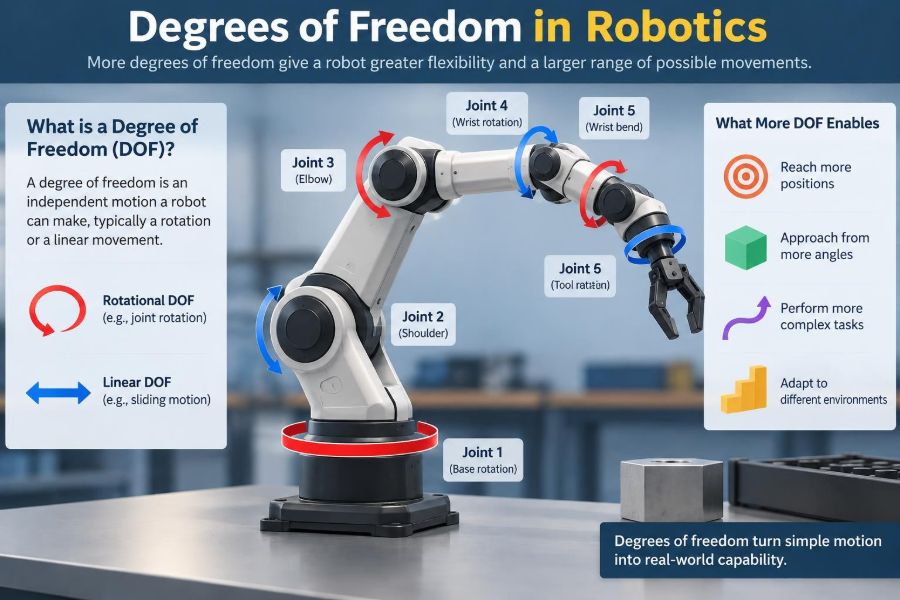
The idea that explains these differences is degrees of freedom, usually shortened to DOF. DOF describes the independent ways a robot or mechanism can move.
It is one of the first concepts robotics students encounter because it connects mechanical design, motion planning, control, sensors, and the real limits of what a machine can accomplish.
🧭 What “Degrees of Freedom” Means
A degree of freedom is one independent motion variable needed to describe a system’s configuration. If changing one variable changes the robot’s position or shape without automatically requiring another variable to change, that variable is a DOF.
A sliding drawer has one DOF: it moves in and out along one line. A door hinge also has one DOF, but it rotates rather than translates. A robot arm combines several such motions so its tool can work in three-dimensional space.
In robotics, DOF may describe a complete mobile robot, a manipulator arm, a gripper, a camera mount, or even a single mechanical linkage.
📦 A Familiar Physical Analogy
Imagine holding a book in empty space. You can slide it left-right, forward-backward, and up-down. Those are three independent translational movements.
You can also rotate it by tilting it side to side, nodding it forward and backward, or twisting it like a steering wheel. Those are three independent rotational movements.
Together, a freely moving rigid object has six DOF: three translations and three rotations. This “six” appears constantly in industrial robotics because a tool often needs full control over both its location and orientation.
📐 Translation: Moving From Place to Place
Translation changes where an object is located without changing which way it faces. Engineers commonly describe the three directions as motion along the X, Y, and Z axes.
For a robot tool, these motions determine whether it can reach a screw, a carton, a workpiece, or a charging dock. A Cartesian gantry robot, for example, often uses three linear slides to provide X, Y, and Z translation.
Three translational DOF can place a tool at a point, but they cannot necessarily aim it correctly. That missing capability becomes obvious when the task involves angled surfaces or oriented parts.
🔄 Rotation: Controlling Direction
Rotation changes orientation. For a robot end effector, orientation determines where a camera points, which way a suction cup faces, or the angle at which a welding torch meets a seam.
Robotics often uses the terms roll, pitch, and yaw for three orientation changes. The exact axis naming convention can vary by field and coordinate-frame definition, but the practical point remains: a tool needs independent rotational control to assume different useful poses.
A robot that can reach a bolt but cannot rotate its driver into alignment cannot complete the fastening task.
🧰 Joints Are Usually the Source of DOF
In a robot arm, degrees of freedom usually come from joints. A joint constrains some relative movement between two links while allowing one or more other movements.
The two most common joint types are:
- Revolute joints, which rotate around an axis, like an elbow or a motorized hinge.
- Prismatic joints, which slide along an axis, like a linear actuator or pneumatic cylinder.
In many practical robot arms, each actuated revolute or prismatic joint contributes one controllable DOF. More complex joints can permit multiple motions, although they require more elaborate mechanisms and control.
🦾 Counting DOF in a Simple Arm
Consider a hypothetical tabletop arm with a rotating base, shoulder joint, elbow joint, and wrist joint. If each joint moves independently, the arm has four joint DOF.
That does not automatically mean it can place and orient its tool arbitrarily anywhere in 3D space. Its links may not be long enough, its joints may have limited travel, and four joint variables are generally insufficient to independently control a full six-DOF pose.
Counting joints is a useful starting point, but it is not the entire answer.
🧮 Joint Space and Task Space
Robot engineers describe motion in two related spaces. Joint space uses the actual joint variables: motor angles for rotary joints and extension distances for linear joints.
Task space, also called Cartesian space, describes what the robot’s tool is doing in the world: its position and orientation. A controller may receive a command such as “move the gripper 100 millimeters upward,” then calculate the joint changes needed to do it.
The mathematical relationship between these descriptions is central to robot kinematics, the study of motion without considering the forces that cause it.
🧠 Forward Kinematics: From Joints to Tool Pose
Forward kinematics answers a direct question: if every joint angle and slide position is known, where is the end effector?
For a simple two-link planar arm, trigonometry can calculate the hand position from the shoulder and elbow angles. For a six-axis industrial arm, the same principle is applied through chained coordinate transformations.
Forward kinematics is generally well-defined for a robot with known geometry. Given a valid set of joint positions, the resulting tool pose can be computed.
🧩 Inverse Kinematics: From Goal to Joint Motion
Inverse kinematics works in the opposite direction. The desired tool pose is known, and the system must find joint positions that achieve it.
This is harder because a pose may have several valid joint configurations, no valid configuration, or solutions that violate joint limits. A human arm demonstrates the idea: you can touch a point in space with your elbow held high or low.
Robotics software often uses geometric methods, numerical optimization, or iterative solvers to find practical inverse-kinematics solutions.
🎯 Position Is Not the Same as Pose
A common beginner mistake is treating “position” and “pose” as interchangeable. Position specifies a location, while pose specifies location plus orientation.
A pick-and-place arm lifting identical boxes from an open bin may need only approximate orientation control. By contrast, inserting a connector into a socket requires the connector’s position and orientation to be closely coordinated.
When a task description includes words such as align, angle, face, tilt, twist, or insert, orientation DOF is likely a major design requirement.
🛠️ Why Six DOF Is a Common Benchmark
A rigid tool moving freely in ordinary three-dimensional space needs up to six independent variables to specify an arbitrary pose. That is why six-axis articulated arms are common in tasks such as welding, machining, inspection, and complex assembly.
Six DOF does not mean every point and orientation is reachable. Geometry, joint ranges, collisions, payload, cable routing, and controller limits still matter.
It does mean the arm has enough independent joint variables, in principle, to control three position coordinates and three orientation coordinates in many parts of its workspace.
🏭 When Fewer Than Six DOF Is Enough
Many automation problems do not require complete pose control. Using fewer axes can reduce cost, complexity, weight, programming effort, and maintenance demands.
A three-axis gantry can move a vacuum tool to known locations above flat trays. A four-axis SCARA robot can rapidly place parts on a horizontal work surface while controlling rotation about the vertical axis.
The right question is not “How many DOF is best?” It is which independent motions does this task actually require?
🧷 When More DOF Creates Redundancy
A robot is called kinematically redundant when it has more joint DOF than the minimum needed for a specified task. A seven-axis arm performing a six-dimensional pose task is a familiar example.
Redundancy gives the controller choices. It may reach the same tool pose while keeping an elbow away from an obstacle, avoiding a joint limit, maintaining a preferred camera view, or reducing awkward cable bending.
That flexibility is valuable, but it complicates planning. The controller must decide which of many possible configurations best satisfies the additional constraints.
🧱 Mechanical DOF Versus Controlled DOF
A mechanism may physically allow a motion without actively controlling it. For example, a passive caster wheel can swivel, and a compliant gripper finger may flex under load.
These are mechanical freedoms, but they are not necessarily commanded axes. In practice, engineers distinguish between the mechanism’s possible motion and the robot’s actively actuated, sensed, and controllable DOF.
This distinction matters for safety and accuracy. An uncontrolled motion may help the system adapt to a surface, or it may introduce uncertainty that must be managed.
🤏 End Effectors Can Add Critical Motion
DOF is not only about the main arm. The end effector can transform what the complete robot system can do.
A parallel gripper usually adds an open-close motion. A two-finger gripper with independently actuated fingers can adapt more flexibly to irregular objects. A wrist-mounted rotary tool adds useful orientation capability even if the arm itself has limited axes.
Tool choice should therefore be considered alongside arm DOF. Sometimes a smarter gripper solves a task more effectively than adding another large robot axis.
🛞 Mobile Robots Have Their Own DOF Story
A robot moving on a flat floor has a planar pose: X position, Y position, and heading angle. In that sense, it has three configuration variables.
But a wheeled robot may not be able to command all three independently at every instant. A standard car-like vehicle cannot slide sideways, and a differential-drive robot must turn while moving rather than translating laterally.
This difference introduces nonholonomic constraints: motion restrictions that affect which paths are possible even though the robot can eventually reach many locations.
🚗 Mobility Does Not Equal Maneuverability
A vehicle may have enough motors to move reliably yet still be unable to take a direct path in every direction. A car can reach a parking space but may need several forward and reverse maneuvers to align with it.
Omnidirectional mobile robots use specialized wheel arrangements to allow lateral motion, which can make precise movement in tight spaces easier. However, those wheel systems can introduce trade-offs in floor tolerance, mechanical complexity, traction, or control.
DOF analysis must account for the robot’s physical contact with the environment, not just its motors.
📏 The Workspace Limits the Useful DOF
A robot’s workspace is the set of positions, and sometimes orientations, its end effector can reach. An arm with many joints can still have a small or irregular workspace if its links are short or joint ranges are restricted.
There is also a difference between a point the tool tip can reach and a pose the complete tool can achieve. A long screwdriver may reach a hole, for example, while its handle collides with a nearby fixture before it can align.
Design reviews should test representative task poses, not merely draw a circle around the robot base and call it reachable.
⚠️ Singularities Reduce Practical Control
A singularity is a configuration where the robot loses effective motion capability in one or more task-space directions, or where achieving a small tool motion requires excessively large joint motion.
Picture a person trying to move their hand sideways with an elbow fully straight. Certain directions become awkward because the arm geometry has temporarily lost leverage and flexibility.
Near singularities, a controller can demand high joint speeds, produce unstable-looking behavior, or struggle to maintain a desired orientation. Good path planning identifies and avoids problematic configurations where possible.
🗺️ The Jacobian Connects Joint Speeds to Tool Speeds
For moving robots, engineers use a matrix called the Jacobian to relate small joint movements or velocities to the end effector’s linear and angular velocity.
Conceptually, it answers: “If each joint moves a little right now, which way will the tool move?” The Jacobian supports velocity control, force control, singularity detection, and numerical inverse kinematics.
You do not need to calculate a Jacobian by hand to appreciate its role. It formalizes the fact that a joint’s effect on the tool changes as the robot changes posture.
🧲 Compliance Changes How DOF Behaves Under Contact
Real robots often interact with objects, people, tools, or surfaces. In those situations, a perfectly rigid position-controlled robot can jam if small alignment errors exist.
Compliance means allowing controlled flexibility or motion in response to force. It can come from springs, flexible mechanisms, force-torque sensors, impedance control, or remote-center-compliance devices used in insertion tasks.
Compliance does not create arbitrary new geometric reach. Instead, it can make the available DOF more useful by accommodating small errors and reducing damaging contact forces.
🔌 Actuators, Sensors, and DOF Must Match
Adding a mechanical axis means more than adding a joint. The axis needs an actuator, transmission, encoder or other feedback method, wiring, control bandwidth, and safety consideration.
Without adequate sensing, a controller may not know the true joint state accurately enough to use the theoretical DOF. Without sufficient torque or stiffness, the axis may sag, lag, or deflect under payload.
A robot’s capabilities are determined by the complete system, not by a headline axis count.
⚖️ More Axes Bring Real Trade-Offs
Extra DOF can improve dexterity, obstacle avoidance, and access to difficult orientations. They can also increase mass, cost, calibration work, failure points, control complexity, and programming time.
Additional joints may reduce stiffness, particularly when long arms carry heavy loads. They can also create more collision possibilities, because every link must be checked against fixtures, workpieces, and nearby equipment.
A well-designed five-axis solution can outperform an unnecessarily complex seven-axis system when the task is constrained and repeatable.
🏗️ Robot Architecture Shapes Available DOF
Different robot forms distribute motion differently. The architecture affects speed, stiffness, workspace shape, accuracy, and ease of integration.
| Robot type | Typical motion arrangement | Well-suited tasks |
|---|---|---|
| Cartesian gantry | Usually linear X, Y, Z axes | Large rectangular work areas, dispensing, simple handling |
| SCARA | Planar rotary joints, vertical slide, vertical-axis rotation | Fast assembly and pick-and-place on horizontal surfaces |
| Articulated arm | Multiple rotary joints, often six or more axes | Complex orientation tasks, welding, machine tending |
| Delta robot | Parallel linkages with a moving platform | Very rapid lightweight picking and sorting |
Axis count alone cannot compare these robots fairly. A four-axis SCARA and a six-axis articulated arm solve different motion problems with different mechanical strengths.
🔍 A Camera Also Needs Useful Degrees of Freedom
Vision systems are frequently mounted on robots, and their DOF requirements deserve separate attention. A fixed camera may inspect a predictable conveyor well, while a wrist-mounted camera can move closer, change viewing angle, and inspect hidden features.
Yet camera motion can introduce blur, calibration challenges, changing lighting, and occlusion. A moving camera is not automatically better; it is valuable when viewing geometry genuinely changes during the task.
In inspection design, ask whether the camera must translate, pan, tilt, focus, or simply observe a controlled scene.
🧪 Choosing DOF From the Task Backward
The most reliable design process begins with the work, not the robot catalog. Define what must move, where it starts and ends, which orientations matter, and what obstacles or contacts occur.
A practical task analysis can include:
- Required tool positions and approach directions.
- Orientation tolerance at each operation.
- Payload, reach, speed, and repeatability needs.
- Obstacles, fixtures, cable paths, and human work areas.
- Whether the environment is structured or varies from cycle to cycle.
- Whether compliance or force feedback is needed during contact.
This process reveals whether another DOF is essential, merely convenient, or unnecessary.
🧾 Example: Picking a Part From a Bin
Suppose a hypothetical robot picks flat, identical parts that always lie face-up in indexed trays. The robot may only need X, Y, Z motion and perhaps one rotation about the vertical axis to match the part’s orientation.
Now change one condition: parts arrive randomly oriented in a deep bin. The robot may need vision, more wrist orientation, collision-aware planning, and possibly a gripper capable of handling variation.
The basic action is still “pick a part,” but the task’s DOF requirements have changed dramatically because the environment and desired approach are less constrained.
🧯 Common Mistakes When Specifying Robot DOF
One mistake is purchasing an arm based solely on axis count. A six-axis robot with unsuitable reach, payload, repeatability, or wrist geometry can be a poor fit.
Another is ignoring orientation until late in the project. Teams may verify that a gripper reaches a part, then discover it cannot approach without striking a fixture.
Also avoid assuming simulation results are final. Models may omit cable behavior, gripper dimensions, sensor housings, part variation, or real joint limits. Validate critical poses on the physical system whenever possible.
🧑💻 Programming Implications of Extra DOF
For a nonredundant arm, a target pose may produce only a small number of useful joint configurations. For a redundant arm, programmers and planning software must often specify preferences such as elbow-up posture, preferred wrist angle, or distance from joint limits.
Modern motion-planning tools can search for collision-free paths, but their success depends on accurate models and sensible constraints. More freedom expands the solution space; it does not eliminate the need for careful planning.
Teaching a robot by manually jogging it can work well for fixed industrial motions. Variable environments often require coordinate frames, perception, path generation, and robust error handling.
🦺 Safety Depends on Predictable Motion
More DOF can allow a robot to route around obstacles, but it also permits more possible movements. Safety design must consider every commanded and unexpected motion that the system can make.
Risk assessment commonly considers pinch points, crushing hazards, reach into shared spaces, stored energy, tool hazards, and faults in sensors or controls. Protective measures may include guarding, safety-rated monitoring, speed limits, interlocks, emergency stops, and collaborative operating modes where appropriate.
DOF is a capability, not a safety feature by itself. Safe use depends on the whole cell design and the applicable safety requirements for the installation.
📚 A Practical Mental Model for Students
When analyzing a robot, start by identifying its links and joints. Then ask what each joint independently changes: position, orientation, shape, or some combination of these.
Next, describe the task as a sequence of required poses and paths. If the tool must be at a location with a particular direction, write down both requirements rather than treating the target as a dot in space.
Finally, check constraints: joint limits, workspace boundaries, collisions, singularities, payload effects, and contact conditions. This habit turns DOF from a memorized number into a useful engineering tool.
🌟 The Core Principle: Capability Comes From Relevant Freedom
Degrees of freedom determine the independent motions a robot can use, but they matter only in relation to a real task. A robot must have enough controllable motion to reach required poses and follow required paths under real-world constraints.
Too few DOF can make an otherwise simple job impossible. Too many can add cost and complexity without improving results. The strongest designs combine appropriate mechanical freedom with suitable tools, sensing, control, workspace, and safety planning.
Whether you are evaluating a desktop arm, designing a factory cell, or studying kinematics, think beyond the number of axes. Ask what motions are independent, what poses are reachable, and what physical constraints shape the answer.
A robot can do only what its usable degrees of freedom, geometry, controls, and environment allow it to do together. That is the practical meaning behind every axis specification. 🦾📐🤖