
A delivery robot leaves a bright lobby, crosses a shaded pavement, enters light rain, and passes between parked cars. Its camera briefly struggles with glare, its wheels slip on a painted line, and satellite positioning becomes unreliable beside tall buildings. Yet the robot must still know where it is and avoid a pedestrian stepping into its path.
No single sensor can describe that situation completely. A camera can recognize lane markings but is affected by darkness. A wheel encoder measures rotation precisely until the wheel skids. A lidar can measure nearby geometry well, but fog, glass, and sparse surfaces can create difficult returns.
Sensor fusion is the engineering discipline of combining these partial, imperfect observations into a more useful estimate of the robot and its surroundings. It is one of the reasons modern robots can operate beyond carefully controlled demonstrations.
For students, sensor fusion connects probability, control theory, embedded systems, and perception. For practicing engineers, it is where a promising robot either becomes dependable in messy conditions or fails because its software trusted the wrong measurement at the wrong time.
🧭 What Sensor Fusion Actually Means
Sensor fusion combines information from multiple sensors, usually over time, to estimate quantities a robot cannot directly know with perfect accuracy. Those quantities may include position, velocity, orientation, a map, obstacle locations, or the state of a robotic arm.
Fusion is not simply placing sensor readings side by side. A useful fusion system accounts for each measurement’s uncertainty, timing, coordinate frame, and likely failure modes. It asks: which observation should influence the estimate most right now?
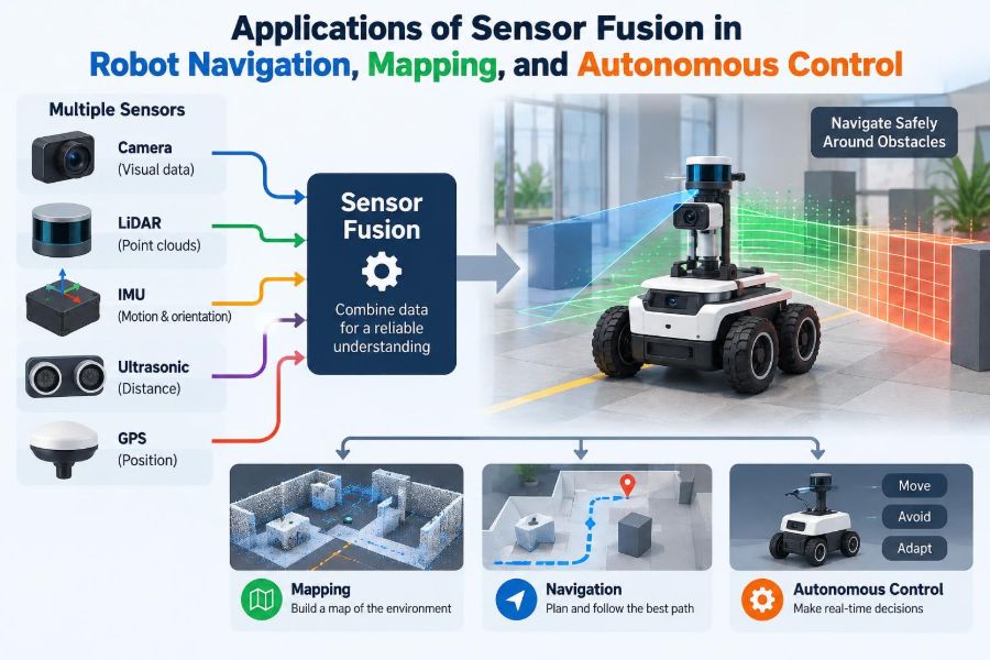
A robot may fuse an inertial measurement unit (IMU), wheel encoders, lidar, cameras, GPS or GNSS, radar, and joint sensors. The best combination depends on the task, environment, cost limits, and safety requirements.
🧩 Why One Sensor Rarely Suffices
Every sensor trades something away. Cameras provide rich visual detail but do not directly provide reliable distance from a single image. Lidar produces explicit range measurements but usually carries less appearance information than a color camera.
Motion also exposes weaknesses. Encoders accumulate error when a wheel slips, while an IMU’s small biases become large position errors after integration over time. GNSS can provide useful global location outdoors, but its accuracy may degrade near buildings, under trees, or indoors.
Fusion makes complementary strengths useful. A high-rate IMU can predict rapid motion between slower camera frames; visual or lidar observations can later correct the IMU’s drift.
📏 The Robot State: What the System Is Estimating
Before selecting an algorithm, engineers define a state: the variables needed for decisions and prediction. For a mobile robot, this often includes position, orientation, linear velocity, angular velocity, and sensor biases.
Consider a ground robot turning through a corridor. Its controller may need its pose—position and orientation—while its estimator also tracks gyro bias. Without estimating that bias, a tiny persistent angular error can gradually rotate the robot’s believed heading away from reality.
State design is practical, not merely mathematical. Estimating too little can hide critical errors; estimating too much can make a system slow, poorly observable, or difficult to tune.
🛰️ Common Sensors and Their Useful Clues
| Sensor | Primary information | Typical limitation |
|---|---|---|
| IMU | Acceleration and angular rate at high frequency | Bias and noise create integrated drift |
| Wheel encoders | Wheel rotation and short-term odometry | Slip, uneven terrain, and calibration error |
| Camera | Appearance, features, semantics, visual motion | Lighting, blur, occlusion, depth ambiguity |
| Lidar | Range and 3D or 2D geometry | Cost, weather effects, weak returns on some surfaces |
| Radar | Range and relative velocity, robust sensing in some weather | Lower spatial detail and clutter interpretation |
| GNSS | Global outdoor position reference | Blocked or distorted signals in difficult environments |
The table is not a ranking. A warehouse vehicle may benefit more from lidar and encoders than GNSS, while an agricultural machine may make GNSS a central part of its navigation stack.
⏱️ Time Synchronization Is Part of the Measurement
Fusion assumes readings describe the same physical world at correctly understood times. If an image is stamped late while a fast robot is turning, associating it with the wrong IMU state can produce a false correction.
Hardware triggering, shared clocks, accurate timestamps, and known communication delays are therefore not optional details. They are part of the sensor model.
This issue becomes especially visible with rolling-shutter cameras, where different image rows are exposed at different times. At speed, treating the frame as instantaneous can bend straight structures or corrupt visual motion estimates.
📐 Coordinate Frames Keep Measurements Meaningful
A wheel encoder measures motion in the vehicle’s local frame. A camera observes points in its optical frame. A map may be expressed in a fixed world frame. Fusion requires known transformations between them.
Extrinsic calibration describes where a sensor sits and how it is rotated relative to the robot body. Intrinsic calibration describes properties internal to a sensor, such as camera focal length and lens distortion.
A lidar mounted a few degrees off its assumed angle can create a map that looks plausible but is subtly warped. Those errors may later appear to be algorithm instability when the actual cause is mechanical alignment.
🎲 Uncertainty Is the Language of Sensible Fusion
Measurements should not be treated as unquestionable facts. A good estimator represents uncertainty: how much variation or error it expects in a reading and in its motion model.
When a camera is blurred, visual observations may deserve less weight. When an IMU experiences vibration, its assumed noise level may no longer match reality. Weighting sources by uncertainty helps prevent a weak observation from overpowering stronger evidence.
Crucially, uncertainty is not the same as ignorance. It is a structured statement about confidence that allows software to make proportionate corrections.
🔄 Prediction and Correction Form the Basic Loop
Most fusion systems alternate between two steps. First, they predict the state forward using a motion model and recent inputs, such as IMU data or commanded wheel motion. Then they correct that prediction when a sensor supplies an observation.
Imagine a robot moving behind a shelving unit where its camera sees little. Its IMU and encoders continue a short-term prediction. When the robot sees a familiar wall corner again, that observation can pull the estimate back toward the correct pose.
This cycle supports continuous operation because sensing is asynchronous: IMU readings may arrive much faster than camera images or map-matching updates.
📊 Kalman Filters and Their Variants
The Kalman filter is a widely taught estimator for systems whose dynamics and measurements can be represented linearly with Gaussian-like uncertainty. It produces an estimate and an associated uncertainty, then updates both when new data arrives.
Real robots are often nonlinear: orientation involves rotations, camera projection is nonlinear, and vehicle motion can change with terrain. The extended Kalman filter approximates nonlinear behavior near the current estimate, while the unscented Kalman filter propagates selected sample points through nonlinear functions.
These methods are valuable because they can run efficiently in real time. They are not automatic solutions; inaccurate models, poor noise tuning, or unhandled outliers can still cause divergence.
🕸️ Factor Graphs and Smoothing
Another major approach represents poses, landmarks, and sensor observations as a graph. Variables are nodes; constraints from IMU motion, scan matching, or visual observations are factors connecting them.
Rather than only refining the present moment, smoothing can optimize a window of past states together. If a robot later recognizes a location it visited before, the system can distribute that new information through its earlier trajectory.
This is powerful for mapping and loop closure, but it may require more memory and computation than a simple filtering approach. Practical systems often use a fast local estimator alongside a slower graph-based optimizer.
🛞 Odometry: Useful, Local, and Fallible
Odometry estimates movement from internal motion sensing. For a wheeled platform, encoder counts and steering geometry can estimate how far and in what direction the robot moved.
It is often smooth and responsive, making it useful for control. But it is usually dead reckoning: small errors accumulate because each new position depends on prior estimates.
On polished floors, a drive wheel may spin without producing matching travel. On loose ground, the relationship between wheel rotation and distance can vary continuously. External observations are needed to bound this drift.
🧠 IMU Fusion Stabilizes Fast Motion
An IMU contains accelerometers and gyroscopes, and sometimes magnetometers. Gyroscopes capture angular motion quickly, which is especially useful for drones, legged robots, and agile mobile platforms.
Acceleration must be interpreted carefully. An accelerometer senses specific force, including the effect of gravity, rather than a clean global acceleration signal. Estimating orientation accurately is therefore central to using IMU data well.
Fusion with cameras, lidar, encoders, or known contacts can constrain the drift that IMU integration creates. The IMU supplies fast continuity; other sensors supply longer-term reference.
👁️ Visual-Inertial Odometry
Visual-inertial odometry combines camera observations with IMU measurements to estimate robot motion. A camera tracks features or image structure, while the IMU helps predict rapid movement and bridges intervals where visual tracking is weak.
A drone flying through a textured indoor space can use this combination effectively because it needs frequent motion updates. However, a blank wall, strong motion blur, repeated patterns, or changing illumination can reduce visual reliability.
Monocular systems also face scale ambiguity unless scale is recovered through motion and inertial information or another source. Stereo cameras and depth cameras can offer direct geometric advantages but add calibration and hardware considerations.
🔦 Lidar-Inertial Navigation
Lidar-inertial systems combine geometric scans with IMU motion estimates. The IMU predicts the platform’s pose while the lidar scan is being collected, and scan matching aligns observed geometry with recent scans or a map.
Because a spinning lidar collects points over time rather than all at once, fast motion can distort a scan. IMU-supported deskewing compensates for that movement before matching.
Long, featureless corridors, open fields, or scenes with repeated structures remain challenging. Geometry alone may not provide enough unique constraints, so additional sensors or map priors can help.
📡 GNSS, Inertial Systems, and Global Reference
GNSS gives a robot an external connection to global coordinates, which is valuable for field robots, outdoor delivery systems, and autonomous vehicles. It does not eliminate the need for local perception.
Satellite signals can be delayed or reflected by nearby surfaces, creating errors that may look convincing unless the system monitors measurement quality. Tunnels, indoor spaces, dense urban areas, and tree cover can create interruptions.
Fusing GNSS with IMU and wheel odometry provides continuity during outages, while local cameras or lidar can maintain lane-level or obstacle-level awareness. A robust design should recognize when GNSS confidence has fallen rather than silently treating every fix equally.
🗺️ Mapping Turns Observations into a Shared Model
A map is more than a picture of where the robot has been. It is a structured representation used for localization, planning, obstacle avoidance, or task-specific reasoning.
Occupancy grids divide space into cells that estimate whether regions are free, occupied, or unknown. Point clouds preserve measured geometry. Semantic maps add labels such as door, aisle, crop row, or charging station.
Sensor fusion improves maps by combining repeated views from different positions. It also introduces a requirement: measurements must be registered to accurate poses, or the map will smear, double edges, and misplace obstacles.
🧭 SLAM Solves Localization and Mapping Together
Simultaneous localization and mapping, or SLAM, addresses a circular problem: a robot needs a map to localize, yet it needs its location to build that map. SLAM estimates both jointly.
In a new warehouse, a robot can use lidar scans and wheel motion to create a layout while estimating its changing pose. As it observes more of the environment, the map provides stronger references for later localization.
SLAM does not guarantee correctness. Dynamic people, moving pallets, reflective surfaces, poor calibration, and insufficient environmental features can all undermine the assumptions behind a clean map.
🔁 Loop Closure Corrects Long-Term Drift
Loop closure occurs when a robot recognizes that it has returned to a previously visited location. This recognition may come from visual place matching, lidar geometry, fiducial markers, or other map evidence.
Suppose a robot drives around a large facility and returns to its start. Its odometry may place the final pose several meters from the initial one. A valid loop closure introduces a constraint that lets an optimizer reduce accumulated error across the trajectory.
False loop closures are dangerous because visually similar corridors or shelves can look alike. Systems need geometric verification and consistency checks before accepting a candidate as a genuine revisit.
🚧 Dynamic Objects Need Different Treatment
Navigation maps work best when the world is mostly static, but real scenes contain people, forklifts, pets, doors, and other moving objects. Treating every observed object as permanent can corrupt localization and maps.
Fusion can separate persistent structure from temporary motion by comparing observations over time, combining object tracking with geometry, and using semantic perception. A detected pedestrian should influence immediate collision avoidance without becoming a fixed wall in the long-term map.
This distinction is task dependent. In a busy factory, traffic patterns may be useful for planning even though individual vehicles are transient.
🎯 Localization Against a Prior Map
Once a high-quality map exists, robots can localize against it rather than build everything anew. A lidar scan can align with structural geometry, while a camera can recognize visual landmarks and an IMU supplies short-term motion prediction.
This approach can be more stable than pure odometry in a known facility. It also has maintenance demands: renovated walls, shifted shelves, seasonal vegetation, or changed lighting can make an old map less representative.
Engineers should define what map changes require remapping and what changes the localization system can tolerate. Map freshness is an operational issue, not only a perception issue.
🤖 Fusion Feeds Autonomous Control
Control algorithms act on an estimated state, not the true state. If a robot believes it is centered in a lane while it is actually drifting toward an edge, even a mathematically sound controller will issue the wrong correction.
For a mobile robot, fused pose and velocity estimates feed path tracking. For a drone, fused attitude and position support stabilization. For a manipulator, fused joint sensing, vision, and force information can guide contact-sensitive tasks.
The key chain is simple: sensors influence estimation; estimation influences control; control changes what sensors see next. Designing these elements independently can hide harmful interactions.
⚡ Latency Can Matter as Much as Accuracy
A highly accurate estimate that arrives too late may be unsuitable for control. This matters when a robot moves quickly or operates close to people and obstacles.
Engineers often distinguish a low-latency local estimator for immediate control from a more computationally expensive global correction process. When a delayed global update arrives, the system must reconcile it carefully with motion that has occurred since the measurement was taken.
Measure end-to-end delay, including sensor exposure, transport, processing, and actuator response. Optimizing only algorithm runtime can miss the actual source of lag.
🛑 Fault Detection Prevents Blind Trust
Fusion improves resilience only if it can recognize suspicious data. A system that averages a faulty measurement into its state without checks can become worse than one with fewer sensors.
Useful safeguards include innovation checks—comparing a measurement with its prediction—range and plausibility tests, sensor health monitoring, and temporary rejection of inconsistent observations. Residuals that remain large may signal calibration shift, a blocked sensor, or an incorrect model.
Redundancy should be meaningful. Two cameras mounted close together may share the same lighting failure, whereas camera, radar, and wheel odometry have more diverse weaknesses.
🧪 Calibration and Validation Are Continuous Work
Calibration is often treated as a one-time laboratory step, but vibration, impacts, thermal changes, repairs, and aging can shift real hardware. A rigid mount and repeatable installation procedures protect estimator assumptions.
Validation should include conditions that expose weaknesses: low light, bright sun, featureless spaces, vibration, wheel slip, rain where relevant, and temporary sensor loss. The goal is not to demonstrate perfect operation; it is to characterize boundaries and safe behavior.
Record synchronized raw data whenever possible. Replaying real logs is one of the most effective ways to compare estimator changes without repeatedly placing a physical robot at risk.
🧰 A Practical Development Workflow
- Define the required state, accuracy, update rate, and failure response for the task.
- Choose sensors based on complementary observability, environmental conditions, mounting limits, and compute budget.
- Establish clocks, timestamps, coordinate frames, and calibration before tuning advanced algorithms.
- Build a simple baseline estimator and inspect its errors with recorded data.
- Add sensors incrementally, with health checks and measurable acceptance criteria.
- Test closed-loop behavior, because a good offline trajectory estimate may still be too delayed or unstable for control.
This workflow avoids a common trap: assembling a large sensor suite before confirming that each data path is understood. More inputs do not compensate for unknown timing or incorrect transforms.
⚠️ Common Failure Modes in Student and Prototype Systems
- Overconfident noise settings: assigning tiny uncertainty makes the estimator resist valid corrections or chase bad data.
- Unmodeled bias: assuming an IMU is unbiased causes gradual but persistent pose errors.
- Frame confusion: mixing left-handed and right-handed frames or using degrees in one component and radians in another produces dramatic failures.
- Ignoring observability: trying to estimate quantities the available motions and sensors cannot reveal reliably.
- Testing only ideal routes: a system tuned in one corridor may fail immediately under different lighting or traction.
When debugging, visualize sensor measurements, transforms, innovations, trajectories, and uncertainty—not just the final robot path. Estimation failures become much easier to diagnose when intermediate quantities are visible.
🔐 Safety Requires Conservative Design
Sensor fusion contributes to safety, but it is not itself a safety guarantee. A robot needs behavior for uncertainty that becomes too large, conflicting sensors, lost localization, and obstacles that cannot be classified confidently.
Possible responses include slowing down, stopping in a safe state, switching to a constrained mode, requesting human assistance, or using an independent protective sensor for emergency detection. The appropriate response depends on the robot’s energy, speed, environment, and task.
Do not assume a sophisticated estimator can replace physical safeguards. Independent emergency stopping, speed limits, protective zones, and system-level hazard analysis remain necessary in many deployments.
🌱 Choosing Fusion for the Environment
There is no universally best sensor stack. A floor-cleaning robot may favor low-cost odometry, IMU data, and simple range sensing. A research drone may need visual-inertial estimation, depth sensing, and careful high-rate control.
Outdoor robots must contend with weather, changing terrain, and global localization. Indoor robots often face GNSS denial, repetitive layouts, people, and changing inventory. Underwater and underground systems bring still different sensing constraints.
Start from failure consequences and environmental observability, then select sensors and algorithms. Starting from a fashionable algorithm often produces unnecessary complexity or misses the actual source of risk.
🧑💻 Skills That Transfer Across Fusion Projects
Strong sensor-fusion engineers move comfortably between theory and physical evidence. They understand probability and linear algebra, but they also inspect mounts, cables, timestamps, temperature effects, and data logs.
Useful habits include plotting trajectories in multiple frames, writing unit tests for transformations, recording reproducible datasets, and separating configuration from code. Small tools that check timestamp monotonicity or transform consistency can save days of debugging.
Communication matters as well. Control engineers, mechanical designers, and operators need a clear description of what the estimate means, how uncertain it is, and what conditions can make it unreliable.
🔮 Where Sensor Fusion Is Heading
Learning-based perception increasingly contributes semantic cues, robust feature extraction, and data-driven associations. These methods can complement geometric estimation, especially when recognizing objects or places that are difficult to describe with simple rules.
However, learned components also need careful validation under conditions unlike their training data. Combining them with explicit geometry, physical motion models, uncertainty handling, and fallback behavior remains a practical engineering direction.
New sensor types and better compute will expand options, but the central questions remain stable: what does each sensor observe, when should it be trusted, and how does its error affect a real decision?
🧠 The Core Principle: Estimate, Question, Correct
Sensor fusion succeeds when a robot continually forms a best current estimate, questions it using new evidence, and corrects it without assuming any sensor is perfect. Navigation, mapping, and autonomous control are different applications of this same disciplined loop.
The most capable systems combine complementary sensing, accurate timing and calibration, realistic uncertainty, fault awareness, and control behavior that respects what the robot does not know. A robot does not become autonomous because it has many sensors; it becomes more capable when those sensors are interpreted together responsibly.
Effective sensor fusion turns imperfect measurements into actionable, uncertainty-aware understanding—and that is the foundation on which reliable robot autonomy is built. 🦾🧭🤖