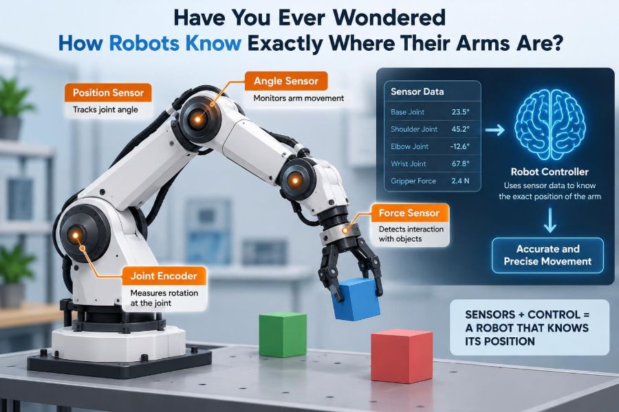

A robot arm on a factory floor can slide a fingertip-sized part into a connector, lift a heavy panel, or trace the same weld seam hundreds of times. It does not pause to look down at its elbow or ask whether its wrist is bent.
That apparent certainty is easy to take for granted. Yet a robot’s controller must continuously answer a deceptively difficult question: where is every part of my arm right now?
The answer is not simply “at the coordinates programmed by an engineer.” Motors flex, gears have small gaps, links bend under load, and sensors contain noise. A reliable robot works because it combines a mathematical model with measured feedback.
That combination is the foundation of robot motion, from industrial manipulators to surgical instruments, collaborative robots, camera gimbals, and the small arms built in student labs.
🧠 The Robot’s Version of Body Awareness
Humans usually know where their hand is even with closed eyes. This ability is called proprioception: the nervous system combines signals from muscles, tendons, joints, and balance organs to estimate body position.
Robot arms need an engineering equivalent. Their control system estimates the angle or displacement of each joint, then calculates where the links, wrist, tool, and payload must be in space.
This is often called robot state estimation. “State” can include joint position, velocity, acceleration, motor current, temperature, and whether the tool has contacted something.
🦾 Start with the Arm’s Mechanical Skeleton
A typical robot manipulator is a chain of rigid links connected by joints. A six-axis industrial arm commonly has joints at the base, shoulder, elbow, and wrist, allowing its tool to reach and orient itself in three-dimensional space.
The controller describes each joint independently before it describes the tool. If joint 2 rotates by a certain angle and joint 3 rotates by another, the rest of the arm follows from the geometry of the connected links.
Real links are not perfectly rigid, but treating them as rigid is a useful first model. More detailed models add flexibility when high accuracy or heavy loads make deflection significant.
🔩 Revolute and Prismatic Joints
Most robot joints fall into two basic categories. A revolute joint rotates around an axis, like a door hinge or an elbow. Its position is measured as an angle, often in radians or degrees.
A prismatic joint moves along a straight path, like the slide in a 3D printer or a linear actuator. Its position is measured as a distance.
Both kinds may appear in one machine. A palletizing robot might rotate at its base and shoulder while using a vertical linear axis to raise and lower an end effector.
📍 Joint Space Comes Before Cartesian Space
Robots use two related coordinate descriptions. Joint space is the list of individual joint positions, such as base angle, shoulder angle, and elbow angle.
Cartesian space, also called task space, describes the tool’s location and orientation relative to a reference frame: for example, a point above a conveyor with a particular gripper rotation.
Sensors usually measure joint space directly. The controller converts that information into Cartesian space because jobs are usually specified in terms of where the tool needs to go.
📐 Forward Kinematics Turns Angles into a Tool Position
Forward kinematics is the calculation that takes known joint values and predicts the pose of the robot’s end effector. A pose includes both position and orientation.
Imagine a flat two-link arm. If both link lengths are known, the controller can use the shoulder and elbow angles to calculate the x and y coordinates of its tip. A spatial robot performs the same idea with three-dimensional rotations and transformations.
Forward kinematics answers, “Given this arm configuration, where is the tool?” It is used constantly for monitoring, visualization, collision checking, and motion control.
🧭 Reference Frames Keep the Math Organized
“The gripper is at x equals 400 millimeters” is incomplete without a reference frame. Is that measured from the robot base, the worktable, a camera, or the conveyor?
Robotic systems define named coordinate frames, often including a base frame, a frame at every joint, a tool frame, and one or more workcell frames. Each frame has an origin and an orientation.
This may sound formal, but it prevents expensive confusion. A camera can locate a package in its own image-based frame, while the robot needs that location converted accurately into its base frame.
🔢 Transformation Matrices Carry Position and Orientation
Controllers commonly represent the relationship between coordinate frames with transformation matrices. These compact mathematical objects describe a rotation and a translation together.
By multiplying transformations in the order of the arm’s links, software carries a point from the tool frame through the wrist, elbow, shoulder, and base. That sequence is the computational heart of forward kinematics.
Students often first encounter these ideas through homogeneous transformation matrices. The notation can look intimidating, but its purpose is practical: it gives software a consistent way to track connected moving parts.
🧮 Inverse Kinematics Solves the Reverse Problem
A robot task usually starts with a desired tool pose: pick this object, place it there, point the nozzle in this direction. Inverse kinematics finds the joint values that can produce that pose.
The reverse calculation is harder because there may be several valid arm configurations. A human can often touch a point with an elbow-up or elbow-down posture; many robot arms have similar alternatives.
Some targets have no solution because they are beyond reach, blocked by a joint limit, or demand an impossible orientation. Good motion-planning software checks those constraints rather than assuming every requested pose is feasible.
📏 Encoders Are the Main Position Sensors
Most robot joints use an encoder, a sensor that measures shaft rotation. It may be mounted on the motor, the output side of a gearbox, or both, depending on the required accuracy and the mechanism.
Optical encoders read patterned discs using light. Magnetic encoders sense changing magnetic fields. Other designs use capacitive or inductive effects. Their technologies differ, but their job is the same: report rotational movement to the controller.
In a linear axis, the equivalent device may be a linear encoder or a rotary encoder interpreted through a leadscrew or belt mechanism.
🌀 Incremental Encoders Count Motion
An incremental encoder produces pulses as a shaft moves. By counting pulses and determining direction, the controller estimates how far the joint has rotated from a known starting reference.
Incremental encoders can provide fine motion information and are useful for speed measurement. But they do not inherently know their absolute starting angle after power is removed.
That limitation explains a familiar startup behavior: some machines slowly move each axis until they find a switch or reference marker. This procedure establishes a known zero position.
🏷️ Absolute Encoders Remember a Position
An absolute encoder reports a distinct code for each angular position, so the controller can identify the shaft’s angle without counting all motion from startup. Multi-turn versions can also track complete revolutions.
Absolute sensing simplifies recovery after a power interruption, but it does not eliminate every problem. The reading can still be wrong if an encoder slips mechanically, a gear train shifts, or a configured zero offset is incorrect.
The choice between incremental and absolute sensing depends on cost, safety requirements, startup behavior, resolution needs, and the machine’s overall architecture.
⚙️ The Encoder May Not Be at the Joint
Motor-side sensing is convenient, yet it measures motor rotation rather than necessarily the final joint angle. Gearbox backlash, belt stretch, torsional compliance, and loosened couplings can create a difference between the two.
For a high-precision arm, an output-side encoder can measure closer to the quantity that matters: the actual joint movement. Some systems use both motor and load-side sensing to observe drivetrain behavior.
This distinction matters especially in flexible or cable-driven robots. An apparently accurate motor position can coexist with a noticeably displaced tool.
🧷 Homing Establishes a Trustworthy Zero
Every position measurement needs a reference. Homing is the procedure that establishes a known joint coordinate, often by moving carefully toward a limit switch, index pulse, mechanical stop, or dedicated calibration fixture.
Once a joint reaches the reference, the controller assigns a defined coordinate value. It can then interpret encoder counts as meaningful physical angles or distances.
Homing must be designed conservatively. A bad direction setting, an unreliable switch, or excessive homing speed can drive an axis into hardware before the control system recognizes the intended reference.
🚧 Limit Switches Are Not Precision Instruments
Limit switches tell a controller that an axis has reached a boundary or reference region. They are essential safety and setup components, but ordinary switches are not automatically precise enough for fine calibration.
Mechanical switches can vary slightly in the point at which they activate. Their repeatability, mounting stiffness, and electrical filtering affect the final homing accuracy.
For demanding applications, a robot may use a coarse switch to find the vicinity and a finer encoder index, vision target, or calibrated fixture to establish the exact reference.
📊 Resolution, Accuracy, and Repeatability Are Different
These terms are often mixed up, but they describe different performance qualities.
| Term | What it describes | Simple example |
|---|---|---|
| Resolution | The smallest change a system can distinguish or command | An encoder detects very small angle increments. |
| Accuracy | How close the reported or achieved pose is to the true pose | The tool reaches the intended hole location. |
| Repeatability | How consistently the system returns to the same pose | The tool reaches nearly the same spot every cycle. |
A robot can be highly repeatable yet not perfectly accurate in the external workspace. If it consistently misses a target by the same offset, a calibrated workcell may compensate for that offset.
🧱 Mechanical Errors Accumulate Along the Arm
A robot’s tool position is influenced by every preceding joint and link. A small angular error near the base can move the tool substantially because all downstream links rotate with it.
Common contributors include gearbox backlash, bearing wear, link deflection, thermal expansion, imperfect link-length measurements, and an end effector that was mounted slightly differently than expected.
The result is a key engineering lesson: high encoder resolution alone does not guarantee high Cartesian accuracy. The sensor is only one component of a larger mechanical system.
🌡️ Temperature and Payload Change the Picture
Machines warm up during operation. Motors, gearboxes, electronics, and metal structures can change temperature, causing small dimensional changes or altering friction and backlash behavior.
Payload also matters. A robot carrying a light suction cup may position differently from the same robot carrying a heavy tool or a long, offset workpiece. Gravity creates torque, and flexible components can bend.
Advanced systems may compensate with thermal models, load-dependent corrections, or external measurement. In less demanding applications, engineers reduce the effect through stiff design, realistic payload limits, and calibration under representative conditions.
🕹️ Servo Control Corrects Position Errors
Knowing the current joint position is useful only if the robot can act on that information. A servo loop compares the desired position with the measured position and commands the motor to reduce the difference.
Position control is commonly nested with velocity and current or torque control. The inner loops respond quickly to motor behavior, while the outer loop ensures the joint follows the planned path.
Feedback is what makes the robot adapt to modest disturbances. Without it, a motor would merely receive a command and hope that friction, load, and voltage changes did not alter the outcome.
🎛️ Why PID Control Appears So Often
Many servo systems use some form of PID control: proportional, integral, and derivative action. The proportional term responds to present error, the integral term addresses accumulated error, and the derivative term reacts to the error’s rate of change.
PID is not a magic recipe. Gains that are too low can make a joint sluggish, while overly aggressive tuning can create oscillation, noise sensitivity, or mechanical stress.
Modern industrial drives may add feedforward, friction compensation, filters, and model-based features. Still, the central feedback idea remains the same: measure, compare, correct, repeat.
🏃 Motion Planning Is More Than Picking Endpoints
A robot should not jump from one joint angle to another. It needs a trajectory: a time-based plan for position, velocity, and often acceleration and jerk, the rate at which acceleration changes.
Smooth trajectories reduce vibration, limit motor torque peaks, and help a tool maintain process quality. For welding, dispensing, machining, and camera motion, the path between points can matter as much as the endpoints.
Controllers often plan in joint space for predictable axis behavior, then evaluate the resulting tool path. Some tasks need carefully constrained Cartesian paths so the tool travels straight or holds a specific orientation.
🧩 Redundancy Gives Some Arms Extra Choices
A six-degree-of-freedom arm can generally control a tool’s position and orientation. A seven-axis arm has one extra degree of freedom, making it kinematically redundant for many tasks.
That extra joint does not automatically improve accuracy. It gives the planner more possible configurations, which can help avoid obstacles, stay away from uncomfortable joint limits, or maintain a preferred elbow posture.
The tradeoff is added complexity. The controller needs rules for selecting among many valid configurations, and small changes in those rules can produce noticeably different arm motions.
⚠️ Singularities Can Make Motion Awkward
A singularity is a configuration where an arm loses an independent direction of motion or where tiny tool-motion requests require very large joint motions. A stretched-out elbow or aligned wrist axes can create familiar examples.
Near a singularity, a controller may slow the motion, change posture, use damped numerical methods, or choose a different path. Otherwise, joint speeds can become impractical even when the requested tool movement is modest.
Singularities are not necessarily mechanical failures. They are geometric properties of a robot’s structure, and planning software must account for them.
👁️ External Sensors Check What Joint Sensors Cannot See
Joint encoders estimate pose from inside the mechanism. External sensors measure the robot, tool, or environment from another perspective.
- Cameras can locate objects and visual markers.
- Force-torque sensors can detect contact forces at a wrist.
- Laser trackers or measurement systems can support high-accuracy calibration.
- Proximity sensors can verify whether a part is present or aligned.
These sensors do not replace encoders in most arms. They supplement them when the task depends on the outside world, especially when parts arrive in variable positions.
🤖 Visual Servoing Lets the Robot Correct from What It Sees
In visual servoing, camera feedback influences the robot’s movement while it performs a task. Rather than relying entirely on a precomputed location, the system adjusts based on observed image features.
For example, a hypothetical pick-and-place cell might detect a component’s offset on a moving tray and correct the grasp pose just before closing the gripper. The camera-to-robot relationship must be calibrated for this to work well.
Vision has limitations: lighting changes, reflective surfaces, occlusion, blur, and calibration drift can degrade results. It is best treated as a measured input with known uncertainty, not as infallible perception.
✋ Force Feedback Tells the Arm About Contact
Position alone cannot tell a robot whether a plug has seated correctly or whether a polishing tool is pressing too hard. Force and torque sensing provide information about physical interaction.
With impedance or force control, the robot can behave less like a rigid position machine and more like a controlled spring. This is useful for insertion, sanding, assembly, and collaboration where compliant contact is desired.
Force signals need careful interpretation. A measured force may come from intended contact, cable drag, acceleration, or a collision, so systems often combine force data with position, velocity, and task context.
🧪 Calibration Aligns the Model with Reality
Calibration reduces the gap between the robot’s mathematical model and the physical machine. It may involve setting joint zeros, measuring tool offsets, identifying the location of a worktable, or refining link parameters.
Tool center point calibration is particularly important. The tool center point, or TCP, is the point the controller treats as the active tip of a gripper, nozzle, cutter, or probe. An incorrect TCP produces incorrect workspace motion even when joint sensing is excellent.
Calibration is not a one-time ritual. Tool changes, impacts, repairs, temperature changes, and wear can justify checking it again.
🛠️ A Simple TCP Error Has Big Consequences
Imagine a welding torch whose programmed TCP is at the tip, but the actual tip is several millimeters away after a replacement. When the robot rotates its wrist, the true tip traces the wrong path.
That error may not be obvious during simple point-to-point moves. It becomes obvious when the tool must follow a seam, insert into a narrow opening, or rotate around a fixed work location.
A practical habit is to verify the TCP with a repeatable fixture or calibration procedure whenever a tool is installed, bumped, or serviced.
🧯 Safety Depends on Knowing Where the Robot Really Is
Robot safety systems use position information to enforce joint limits, speed restrictions, workspace boundaries, and monitored zones. If the pose estimate is unreliable, a controller cannot confidently apply those protections.
Safety-rated systems may use redundant sensing, diagnostics, plausibility checks, and specialized certified components. Their design is different from simply adding an ordinary software limit to a hobby project.
Do not assume a simulation boundary is a physical safeguard. Safe deployment requires appropriate risk assessment, guarding or collaborative measures where applicable, validated limits, and procedures suited to the machine and task.
🔍 Fault Detection Looks for Disagreement
A robust robot does not blindly trust one number. It can compare commanded position with measured position, motor-side motion with output-side motion, expected torque with measured current, or camera observations with kinematic estimates.
Large or persistent disagreement can indicate a collision, stalled axis, broken coupling, encoder issue, or unexpected load. The right response depends on the machine, but it may include a controlled stop, fault message, or safe-state transition.
Filtering is necessary because every sensor contains noise. The challenge is to reject harmless fluctuations without masking a fast, genuinely dangerous event.
🧑💻 What Students Can Learn from a Small Arm
A desktop arm, pan-tilt mechanism, or 3D printer axis can demonstrate the same principles at lower cost and lower risk. Start by commanding one joint, reading its encoder, and plotting measured position against the target.
Then build a simple forward-kinematics model and compare the predicted tip location with a measured location. The mismatch is not a failure of the exercise; it reveals calibration error, backlash, flex, and assumptions in the model.
- Define clear joint-zero conventions.
- Keep units consistent throughout the software.
- Log commands, sensor readings, and faults.
- Test slowly before increasing speed or payload.
🧰 Practical Checks for Working Engineers
When an arm seems to “lose its place,” separate the problem into layers. Is the encoder reading stable? Does the joint physically follow the encoder? Does forward kinematics match a measured tool pose? Is the tool frame correct?
This structured approach avoids a common trap: changing controller gains to hide a mechanical or calibration issue. Tuning can improve tracking, but it cannot repair a slipping gearbox or a wrongly entered tool offset.
Trend data is valuable. Increasing following error, unusual motor current, or worsening repeatability can reveal wear before it becomes a production stoppage.
🚫 Common Misunderstandings About Robot Position
One misconception is that a robot “knows” its location in the human sense. It does not. It maintains an estimate based on sensor readings, models, and assumptions, each with possible error.
Another is that GPS is how robots locate their arms. GPS can help mobile machines estimate an outdoor global position, but it is far too coarse and unsuitable for measuring individual arm joints in most workcells.
A third is that more sensor resolution automatically solves accuracy problems. If the structure flexes or the coordinate frames are wrong, finer counts simply describe the wrong physical model more precisely.
🔄 The Core Loop: Sense, Model, Plan, Correct
Robot arm awareness is best understood as a loop rather than a single measurement. Sensors report joint motion; kinematics converts that motion into a tool pose; planning generates a desired motion; servo control corrects the difference.
Calibration and external sensing keep the loop grounded in reality when mechanical imperfections or environmental variation matter. Safety monitoring watches for conditions in which the estimated state can no longer be trusted.
This layered design explains why capable robots can perform precise work repeatedly without needing a human to guide each movement.
🎯 The Essential Takeaway
Robots know where their arms are by combining joint sensing, geometric models, coordinate transformations, calibration, and feedback control. No single encoder reading is the whole answer.
The more demanding the task, the more engineers must account for real-world effects: compliance, backlash, heat, payload, imperfect tool installation, sensor noise, and changing workpieces. Precision comes from managing the whole system, not from one impressive component.
A robot arm is accurate when its measurements, mechanics, mathematics, and control loops agree closely enough for the job it must do. That is the practical meaning behind a robot that seems to know exactly where its hand is. 🦾📐🤖