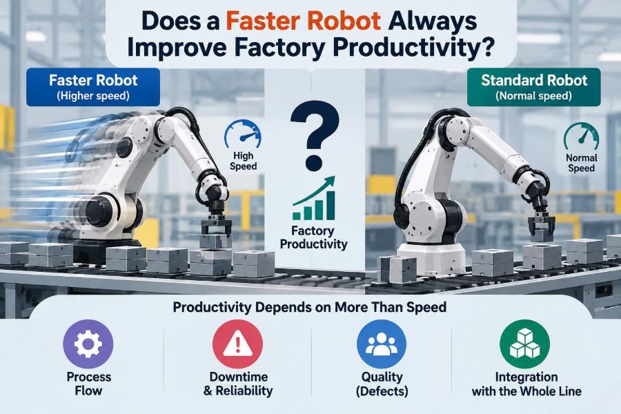

A production manager sees a robotic cell waiting on a fixture, a pallet queue growing upstream, and an order deadline approaching. The obvious response is tempting: increase the robot speed.
After all, the robot’s datasheet may show impressive maximum joint velocities and short cycle times. If the machine completes each motion faster, shouldn’t the factory automatically make more parts per shift?
Sometimes it will. In many real cells, however, the robot is not the limiting resource. Speeding it up can simply move the waiting time to another station, increase faults, or create a quality problem that consumes the apparent gain.
Factory productivity is a system outcome, not a robot specification. Understanding that distinction helps engineers choose changes that raise useful output rather than merely making one machine look busy.
🏭 Productivity Is More Than Robot Speed
Robot speed describes how quickly an arm can move through a programmed path. Factory productivity describes how many good, saleable parts leave the process over a defined period, using acceptable labor, energy, material, and equipment resources.
A robot can move rapidly while the line produces nothing if it is waiting for parts, waiting for permission from a safety system, or repeatedly stopping for rejects. Conversely, a modestly paced robot can support excellent output when every surrounding process is well synchronized.
The useful question is therefore not “Can the robot move faster?” It is “What prevents the next good part from leaving the factory sooner?”
⏱️ Cycle Time Is the First Number to Understand
Cycle time is the time required to complete one repeated unit of work. In a robotic welding cell, it may include loading, clamping, welding, inspection, unclamping, unloading, and the robot’s travel between points.
A robot motion may account for only part of that total. Reducing a two-second travel motion matters less when the full cell cycle includes a longer weld, a fixture change, and an operator interaction.
Engineers should measure the whole recurring sequence, not estimate it from the robot program alone. A time study or controller trace often reveals waits that are invisible during casual observation.
🔗 The Slowest Required Step Sets the Pace
In a serial process, each unit must pass through every required operation. The step with the lowest sustained capacity is the bottleneck, and it constrains the output of the entire line.
Imagine a robot that can load 30 assemblies per hour into a test station that can validate only 20 per hour. Raising robot capacity to 40 per hour does not create more validated assemblies. It produces a larger queue, unless the test step is changed too.
This is why local efficiency and line throughput are different measures. Keeping every robot active can even be counterproductive if it creates excessive work-in-progress inventory.
🚦 Throughput Depends on Flow, Not Just Motion
Throughput is the rate at which a process completes good units. It depends on the flow of material, information, tooling, people, and decisions through the system.
A robot may finish its task early but remain idle while a conveyor indexes, a vision camera processes an image, or a material handler replenishes trays. Those delays are part of the actual production rhythm.
Think of an airport security line: making one officer check documents faster does not shorten the journey if the bag scanner, boarding gate, or passenger queue is the real constraint.
📊 Takt Time Clarifies What the Customer Requires
Takt time is the available production time divided by the customer demand during that period. It expresses the average interval at which the process must complete a unit to meet demand.
If a cell already completes a good unit comfortably within takt time, making its robot faster may provide useful buffer, but it may not increase revenue-producing output. Demand, downstream capacity, or planned production volume may already be the limit.
If the cell cannot meet takt time, faster robot motion could help—but only after verifying that robot motion is a meaningful portion of the missed time.
🧮 Separate Robot Time From Cell Time
A practical analysis divides the cycle into elements. This prevents teams from trying to solve every problem with motion speed.
| Cycle element | Typical examples | Can faster robot motion help? |
|---|---|---|
| Robot motion | Approach, transfer, retreat, reposition | Often, if paths and accelerations are limiting |
| Process time | Welding, dispensing, curing, machining, screwdriving | Usually limited; changing it may affect quality |
| Machine interaction | Door cycle, clamp confirmation, conveyor index | Only indirectly |
| Human interaction | Loading, inspection, replenishment | Not directly |
| Waiting and faults | Part absence, retries, alarms, communication delays | Rarely; remove the cause instead |
Record both average time and variation. A short average cycle can still deliver poor output if occasional delays are frequent or long.
🧱 Bottlenecks Can Move After an Improvement
Suppose a pick-and-place robot is the initial bottleneck. Its path is optimized, and the cell now runs faster. That is a real gain—but the bottleneck may then shift to label printing, final inspection, or packaging.
This is normal. Improvement should be iterative: identify the current constraint, improve it, then observe the new system behavior. Treating a speed increase as a permanent solution overlooks how connected processes respond.
A useful result is not merely a faster robot; it is a verified increase in completed good units at the line’s output.
🎯 Maximum Speed Is Not Production Speed
Robot manufacturers specify maximum axis speeds and accelerations under defined conditions. A production application rarely uses those maximums continuously.
Payload, tool geometry, reach, wrist orientation, path shape, accuracy requirements, collision margins, and safety limits all affect the usable speed. A heavy end effector at long reach imposes different dynamic loads than a bare robot moving near its base.
Programs should be tuned for the real task. Selecting a speed percentage simply because it is available is not an engineering justification.
📐 Acceleration Often Matters More Than Top Velocity
Many robotic moves are short. In a short point-to-point move, the robot may spend most of the motion accelerating and decelerating, never reaching its programmed maximum velocity.
That means an increase in maximum speed may produce little cycle-time reduction. Better blending between moves, a shorter path, or safely adjusted acceleration may have a larger effect.
Higher acceleration also raises forces, vibration, and settling demands. The best setting is the fastest motion that remains stable, accurate, and reliable—not the most aggressive curve the controller will accept.
🛤️ Path Planning Can Beat Raw Speed Settings
Unnecessary waypoints, conservative approach distances, and stop-start trajectories are common sources of wasted time. A robot that fully stops at every programmed point behaves differently from one that smoothly blends suitable transitions.
Path optimization might include reorienting a part presentation, moving home positions closer to the work, combining compatible motions, or reducing an overly cautious clearance after validating the new path.
These changes require careful collision checking and physical trials. A shorter path that occasionally clips a cable, fixture, or part is not an improvement.
⚖️ Payload and Inertia Limit Dynamic Performance
Payload is not just the mass carried by the robot. The location of that mass matters. A long gripper, offset tool, or large panel can create high moment of inertia, meaning the robot needs more torque to accelerate, decelerate, and control it.
Incorrect payload data can lead to poor motion behavior, position errors, protective stops, or mechanical stress. It can also make speed optimization misleading because the controller is working from the wrong dynamic model.
Measure and configure tool mass, center of gravity, and inertia as accurately as the robot system permits. This is foundational setup work, not an optional refinement.
🔧 End Effectors May Be the Real Limitation
The robot arm may be capable of a quicker cycle while its gripper is not. Vacuum cups need time to establish reliable suction; pneumatic grippers need actuator travel and sensor confirmation; a dispensing valve needs controlled opening and closing.
Tool changes may introduce hose motion, cable strain, or part swing. A faster arm can amplify these effects, causing dropped parts or inconsistent placement.
When an end effector limits the cycle, solutions may include a lighter design, faster actuation, better sensors, improved air supply, or a different gripping strategy—not simply a higher robot speed command.
🧪 Process Quality Has Its Own Time Requirements
Some processes deliberately require time. Adhesive beads need a controlled application rate. Welding needs appropriate travel speed and energy input. Vision inspection may require a stable image. Screwdriving needs engagement and torque verification.
Reducing the robot’s dwell or travel time can change process results even when the robot still reaches every position. A faster weld path, for example, is not automatically equivalent to a faster non-process move.
Separate non-value-added delay from process time that protects function, appearance, or compliance. Validation should confirm the finished part, not only the controller’s cycle timer.
📏 Accuracy and Repeatability Can Suffer
Robots are valued for repeatability: their ability to return to similar positions repeatedly. At higher speeds, structural flex, tool deflection, cable movement, and vibration can make a process less consistent even if the robot’s nominal position data remains unchanged.
Fine tasks such as connector insertion, sealant application near an edge, or loading a precision fixture may need a controlled approach and settling period. A few saved tenths of a second are expensive if they create rework.
Check quality at the proposed production rate, across normal operating conditions, rather than approving a change after only a few favorable cycles.
📈 Variation Is as Harmful as a Long Average Cycle
A process that averages 40 seconds but sometimes takes 70 seconds can disrupt downstream equipment more than a predictable 45-second process. Buffers may absorb some variation, but they are finite.
High speed settings can increase variation when they cause occasional retries, missed picks, vision failures, or minor protective stops. The apparent average improvement may disappear once these events are included.
Look at the distribution of cycle times: typical cycles, slow cycles, stops, and recovery time. Stable production planning depends on this broader picture.
🛑 Reliability Turns Small Faults Into Lost Output
A faster cell that faults more often may have lower useful capacity than a slower, dependable one. A stop costs more than the moment it occurs: someone must notice it, diagnose the condition, recover safely, inspect parts, and restart the sequence.
Common speed-related fault mechanisms include parts shifting in a gripper, sensor timing becoming marginal, cables snagging, overshoot at a fixture, and product arriving before another device is ready.
Monitor fault codes before and after changes. If a modification raises intervention frequency, its true productivity benefit must include that lost recovery time.
🧰 Availability and OEE Put Speed in Context
Many factories use overall equipment effectiveness, or OEE, to frame performance. It combines availability, performance relative to an ideal rate, and quality of produced parts.
A faster programmed rate can improve the performance component, but only if availability and quality remain intact. More downtime or more rejects can offset the gain.
OEE is a useful diagnostic framework, not a substitute for understanding the process. Its numbers are meaningful only when planned time, downtime categories, ideal cycle assumptions, and quality records are defined consistently.
🔄 Upstream Starvation and Downstream Blocking Waste Capacity
Starvation occurs when a robot has no incoming part to process. Blocking occurs when it cannot release a finished part because the next location is full or unavailable.
Neither condition is fixed by making the robot’s own motion quicker. Starvation may point to an unreliable feeder or slow prior operation. Blocking may reveal insufficient buffer capacity, a slow inspection station, or poor conveyor coordination.
Controller logs, stack-light histories, and simple observations of machine states can distinguish these conditions from genuine robot-limited time.
📦 Buffers Are Useful, but They Are Not Free
Small buffers can decouple stations and absorb normal variation. For example, a short accumulation conveyor can prevent a brief vision delay from immediately stopping an upstream robot.
Too much buffering, however, hides problems, increases floor-space use, ties up inventory, and makes defects travel farther before discovery. It may also complicate traceability.
Design buffers around the expected variation and recovery behavior of the line. Do not use a large queue as the default answer to an unstable process.
👷 People and Material Supply Still Shape Output
Automation does not remove human and logistical constraints. Operators may load fixtures, replenish consumables, inspect exceptions, clear jams, or pack completed goods. Forklifts and autonomous mobile robots must deliver material at the right time.
If a robot finishes more quickly than parts are supplied, the improvement exposes a material-handling weakness rather than increasing output. The same applies to labels, fasteners, weld wire, adhesive cartridges, and empty containers.
Include these support activities in the process map. Production systems fail at handoffs as often as they fail at the main operation.
🦺 Safety Settings Are Production Requirements
Safeguarding is not a variable to bypass in pursuit of cycle time. Safety-rated scanners, interlocks, light curtains, guarded zones, collaborative speed limits, and safe stop functions exist to control hazards created by moving machinery.
A speed change can alter stopping distance, reach into adjacent zones, payload behavior, and the risks to people performing loading or maintenance. It may require a review of the risk assessment and validation of protective measures.
Work within applicable regulations, machine safety standards, manufacturer instructions, and site procedures. Qualified safety personnel should be involved whenever a change can affect hazards or safeguarding performance.
🤝 Collaborative Robots Need Context-Specific Speed Choices
Collaborative robots are often associated with working near people, but “collaborative” does not mean unrestricted high-speed operation. Their permitted behavior depends on the application, tooling, payload, workspace, contact risks, and safeguarding strategy.
A cobot doing a low-force handoff may have different limits from one carrying a rigid metal fixture. Adding a sharp tool or a heavy gripper can materially change the risk profile.
Productivity may come from better task sharing, ergonomic fixture design, or reduced walking—not necessarily from faster collaborative motion.
🔍 Vision, Sensing, and Control Latency Add Time
Automated cells increasingly depend on cameras, barcode readers, force sensors, PLCs, networks, and databases. Each can add delay or variability through image processing, communication handshakes, retries, and decision logic.
For a vision-guided pick, the robot may be waiting not for its motors but for a reliable pose estimate. Reducing arm motion time by a fraction may have little value if image acquisition and processing dominate the sequence.
Measure timestamps across devices where possible. This identifies whether optimization belongs in robot code, PLC sequencing, lighting, network design, or the vision algorithm.
🧠 Better Sequencing Often Creates Hidden Capacity
Some tasks can occur in parallel. While one fixture is being unloaded, a second fixture may be positioned. While the robot travels toward a pick location, a gripper command may begin if the tool and safety logic allow it.
Good sequencing overlaps compatible actions without violating process dependencies. It is often more effective than aggressively shortening every move.
For example, in a hypothetical dual-station cell, the robot can work at station A while an operator safely loads station B behind guarding. The gain comes from reducing idle overlap, not asking the robot to race.
🧩 Cell Layout Influences the Best Possible Cycle
Layout determines travel distances, reach posture, access for maintenance, cable routing, operator ergonomics, and material flow. A robot placed centrally between two tasks may have a much lower travel burden than one forced to shuttle across a wide fixture.
Changing layout is more disruptive than editing a speed value, but it can remove a structural limit that software tuning cannot solve. Fixture orientation and part presentation are especially influential.
Before purchasing a larger or faster robot, examine whether the current workspace makes efficient motion physically impossible.
💻 Simulation Is Valuable, but It Has Limits
Offline simulation can compare layouts, check reach, estimate cycle time, and identify collision risks before changes reach the floor. It is particularly useful when evaluating alternate robot sizes, fixture positions, or multi-robot coordination.
Yet a simulated cycle may omit real-world effects: part tolerances, hose stiffness, gripper wear, sensor noise, feeder behavior, operator timing, and controller communication delays. Treat simulated gains as estimates to validate, not guaranteed production results.
The strongest workflow combines simulation with measured data and a controlled on-machine trial.
🧾 A Practical Method for Deciding Whether to Increase Speed
Use a disciplined test rather than a broad “speed up everything” change. Establish a baseline over representative production, including normal product variation and routine support activity.
- Measure completed good parts, full cell cycle time, waits, faults, downtime, and rejects.
- Identify the current bottleneck and quantify how much of its time is genuinely robot motion.
- Choose one change, such as path blending, a shorter approach, or a revised sequence.
- Review safety implications and validate collision clearance, tooling behavior, and process requirements.
- Run enough representative cycles to observe quality, stability, and recovery behavior.
- Compare output at the line exit, not only the robot’s internal cycle counter.
Document the result and preserve a safe, known-good backup of programs and parameters. Controlled experimentation makes later troubleshooting far easier.
⚠️ Common Speed-Optimization Mistakes
Several shortcuts repeatedly lead to disappointing improvements:
- Using the robot’s maximum speed setting without timing the entire cell.
- Optimizing a non-bottleneck station while the true constraint remains untouched.
- Ignoring payload data, tool dynamics, and part stability.
- Approving a change based on a few cycles rather than normal production conditions.
- Counting gross cycles while overlooking rejects, rework, and recovery time.
- Changing motion or safety behavior without formal review and documentation.
The common thread is local thinking. Productivity improves when the team evaluates the process as an interacting system.
🛠️ When a Faster Robot Really Does Help
Speed optimization is worthwhile when evidence shows that robot travel or manipulation is the active bottleneck, the surrounding process can accept the increased rate, and quality and safety remain validated.
Typical candidates include long non-process transfers, excessive waypoint use, slow pick-and-place cycles with stable lightweight parts, and poorly sequenced motions that can be blended or overlapped.
The improvement may be a modest parameter adjustment, a redesigned gripper, a better fixture orientation, or a revised program. The right answer is the one that increases sustained good output with acceptable risk and maintenance burden.
🌟 The Core Principle: Optimize the System, Not the Spectacle
A fast-moving robot is visually impressive, but motion speed is only one lever in factory performance. The limiting factor may be process time, quality verification, supply, reliability, safety, or an entirely different machine.
Start with the demand rate and the flow of good parts. Measure the whole cell, locate the constraint, then make the smallest well-validated change that removes it. Repeat as the bottleneck moves.
This approach produces a more useful kind of automation: not equipment that appears fast, but a production system that delivers predictably.
A faster robot improves factory productivity only when its speed removes a real system constraint without sacrificing safety, quality, or reliability. That is the standard worth designing and measuring for. 🦾📈🏭