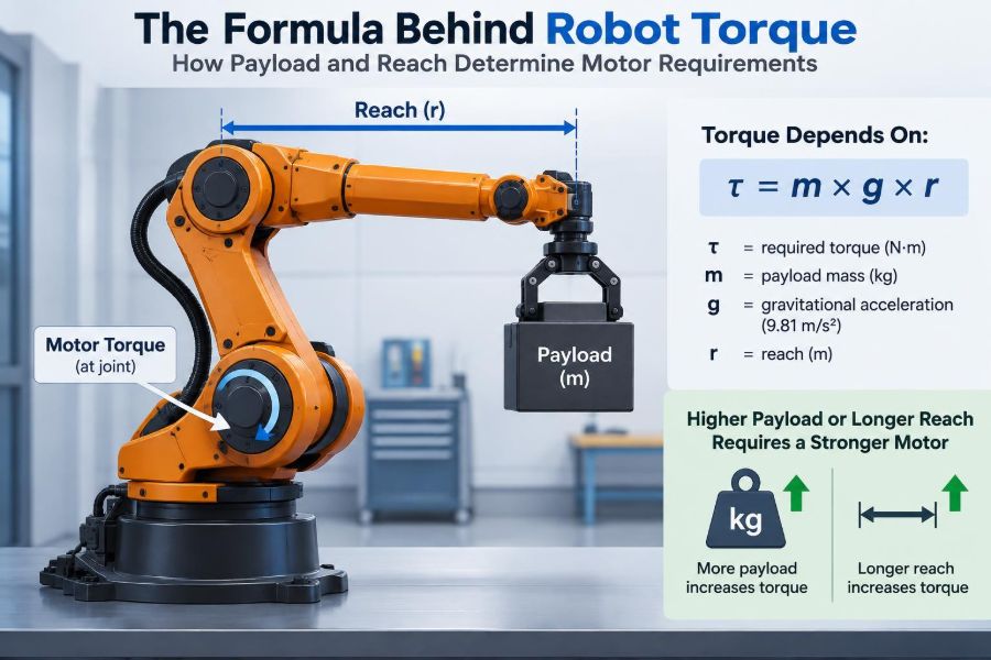

A robot arm can look perfectly capable on a workbench, then fail the moment it tries to lift a real object at full extension. The motor turns, the controller reports no obvious fault, yet the arm sags, stalls, or overshoots its target.
The missing variable is often not payload alone. A 2 kg tool held close to a joint may be easy to move, while a much lighter tool at the end of a long arm can demand far more from the same motor.
This is the practical meaning of torque: the turning effect a force creates around an axis. It determines whether a robot can lift, hold, accelerate, and stop its links without overheating motors or damaging gearboxes.
Understanding the underlying formula turns motor selection from guesswork into an engineering process. It also reveals why reach, center of mass, acceleration, gravity direction, and drivetrain details all belong in a credible design calculation.
🧭 Start with the Real Design Question
“What motor can lift my payload?” is useful, but incomplete. The more precise question is: what torque must each joint deliver throughout the required motion?
A joint may need very little torque when the arm points downward, then reach its maximum requirement when a link is horizontal. It may also need a brief, much larger torque pulse to accelerate or decelerate the same load.
Motor sizing therefore begins with the robot’s geometry and duty, not with a motor catalog.
🔄 Torque Is a Rotational Force
Torque is the rotational equivalent of force. Push a door near its hinge and it barely moves; push at the handle and the same force produces a much stronger turning effect.
For a force perpendicular to a lever arm, the basic relation is:
τ = F × rHere, τ is torque in newton-metres (N·m), F is force in newtons, and r is the perpendicular distance from the joint axis to the line of action of that force, in metres.
📏 Why Reach Multiplies the Problem
Reach is not just a workspace feature. It is a torque multiplier. Double the distance from a joint to a payload’s center of mass, and the gravitational torque at that joint doubles.
This explains why long-reach cobots, camera booms, and pick-and-place arms need careful mechanical design. Extra reach can increase loads on upstream joints, bearings, gearboxes, and supporting structure even when the payload rating does not change.
Distance must be measured from the joint axis, not from the outside of a motor housing or the end of a link.
🌍 Convert Mass into Weight Force
Payload is often specified in kilograms, but torque equations use force. On Earth, the weight force is approximately:
F = m × gm is mass in kilograms, and g is gravitational acceleration, approximately 9.81 m/s². A 3 kg payload therefore creates about 29.4 N of downward force.
For conceptual estimates, engineers may round g to 9.8 or 10 m/s². Final designs should use a consistent value and retain sensible precision rather than creating false accuracy.
🧮 The Core Static Payload Formula
When a payload is held with its lever arm perpendicular to gravity, its static torque is:
τpayload = mpayload × g × rpayloadSuppose a 2 kg gripped part has its center of mass 0.45 m from a shoulder joint. The payload contribution is:
τpayload = 2 × 9.81 × 0.45 = 8.83 N·mThat value only describes holding the payload still. It does not yet include the gripper, links, acceleration, friction, safety margin, or transmission losses.
🎯 Use the Payload Center of Mass, Not the Tool Tip
A payload is rarely a point mass at the tool tip. Its relevant location is its center of mass: the point at which its weight can be treated as acting for a simple gravity calculation.
A compact part centered near the gripper mounting face may impose less torque than a long screwdriver, camera, welding torch, or carton extending outward from the flange. A changing payload, such as a bottle being filled, requires checking its heaviest and most unfavorable center-of-mass condition.
If the exact center of mass is unknown, use a conservative estimate and validate it with a physical measurement or supplier data when possible.
🧰 The End Effector Counts as Payload
The robot must carry everything beyond the joint, not just the workpiece. A gripper, vacuum cup, adapters, cables, sensors, and protective guards all contribute mass and torque.
For a wrist joint, the correct external load is often the combined mass and center of mass of the end effector plus the object. For upstream joints, those same items are farther away and can create substantially greater torque.
- Gripper or tool body
- Mounting plate and fasteners
- Vacuum fittings, hoses, and cable dress
- Payload in its worst allowed position
- Material buildup, such as residue or multiple picked items
🦾 Links Have Weight Too
A shoulder motor must carry the payload, end effector, forearm, wrist assembly, and sometimes part of its own transmission. Ignoring link mass is one of the most common errors in early arm calculations.
For a uniform straight link, its center of mass is approximately halfway along its length. A 0.6 m link weighing 1.5 kg therefore has a gravitational moment around its proximal joint based on an approximately 0.3 m lever arm, before attached components are added.
Real links are not always uniform. Motors, gearboxes, covers, and cable bundles shift the center of mass, so CAD mass properties are especially valuable as a design matures.
🧩 Add Contributions Joint by Joint
Static gravity torque at a joint is the sum of every downstream component’s weight multiplied by its perpendicular distance from that joint.
τgravity = Σ(mi × g × ri)The summation includes each link, actuator, tool component, and payload that the joint supports. Each item has its own mass mi and lever arm ri.
This is why the base joint of a serial arm is usually the hardest to size. It supports the greatest collection of downstream masses and often sees the longest effective reach.
📐 Account for Arm Angle
Gravity does not always act at a 90-degree angle to the link. Only the perpendicular component of the lever arm produces torque.
If θ is the angle between the lever arm and the gravity direction, then:
τgravity = m × g × r × sin(θ)Torque is highest when the arm is horizontal relative to gravity and approaches zero when the center of mass lies directly below or above the joint axis. Define angles carefully; in some coordinate conventions, the same relationship is written with cosine instead.
🗺️ Find the Worst-Case Pose
The maximum reach pose is often severe, but it is not automatically the worst pose for every joint. A wrist may peak during a tool orientation change, while an elbow may peak when the upper and lower links align in a particular configuration.
Build a list of credible poses: fully extended, folded, overhead, loading, unloading, and any constrained production posture. Calculate gravity torque for each, then retain the highest magnitude for sizing.
For multi-axis robots, simulation or a spreadsheet connected to forward kinematics can prevent a costly oversight.
⚡ Holding Torque Is Not Moving Torque
Static torque answers whether a robot can hold a position. Motion introduces inertia: resistance to angular acceleration.
The rotational dynamic term is:
τacceleration = I × αI is moment of inertia in kg·m² and α is angular acceleration in rad/s². The required joint torque is commonly estimated as gravity torque plus acceleration torque, with additional allowances for friction and losses.
🌀 Moment of Inertia Explains “Hard to Start”
Mass alone does not describe a moving arm. A mass far from the axis is harder to accelerate and decelerate than the same mass near the axis.
For a point-like payload:
I = m × r²Notice the squared distance. Doubling reach makes the payload’s rotational inertia four times larger. Long reach therefore hurts both static gravity loading and dynamic performance, though by different mathematical relationships.
🏃 Acceleration and Cycle Time Raise Demand
A slow inspection arm may be governed mostly by gravity torque. A fast packaging robot may need much more torque for acceleration, braking, and rapid direction reversal.
Suppose a hypothetical payload has 0.5 kg·m² of inertia around a joint and must accelerate at 8 rad/s². Its acceleration torque alone is 4 N·m. That requirement exists even in a horizontal-plane motion where gravity contributes little at that axis.
Shorter move times tend to require higher acceleration, but trajectory shape matters too. Abrupt commands create larger torque peaks than smooth, jerk-limited motion profiles.
🛑 Deceleration Can Be the Critical Case
Designers sometimes calculate only the torque needed to lift or accelerate. Stopping can be equally demanding because the drive must remove kinetic energy and control the load without overshoot.
In a downward move, gravity may assist acceleration but oppose braking. Depending on the direction and pose, the motor may need to apply substantial torque simply to decelerate safely.
Regenerative energy can also raise electrical design questions. A drive may return energy to a DC bus during braking, requiring a suitable energy-handling path such as regeneration hardware or a braking resistor.
⚙️ The Complete Joint-Torque Estimate
A useful first-order model is:
τjoint = τgravity + Iequivalent × α + τfriction + τexternalτexternal covers process forces, such as pressing, sanding, cutting, cable forces, or contact with a fixture. Signs matter: individual terms may help or oppose each other depending on direction.
This equation is a model, not a substitute for validation. It becomes more accurate as the inertia, friction, transmission, and motion assumptions become more realistic.
🔧 Reflected Inertia Connects the Load to the Motor
A gearbox changes speed and torque, and it also changes how load inertia appears at the motor shaft. For an ideal reduction ratio N, defined as motor speed divided by output speed, output inertia reflected to the motor is approximately:
Imotor-reflected = Iload / N²Reduction can make a large arm inertia easier for the motor to accelerate. But this does not make inertia disappear; the gearbox must still transmit the resulting output torque, and real systems add gearbox inertia, friction, compliance, and efficiency losses.
⚖️ Gear Ratio Trades Speed for Torque
In an ideal reducer, output torque rises roughly in proportion to gear ratio while output speed falls by the same ratio. Real output torque is better represented as:
τoutput = τmotor × N × ηη is transmission efficiency, which is below one and may vary with load, speed, lubrication, temperature, and gearbox type. Never assume a reducer delivers its ideal torque multiplication without losses.
High ratios help hold heavy loads, but can limit joint speed and may introduce backlash, compliance, or reduced backdrivability.
📉 Read Motor Torque Curves Correctly
A motor’s headline torque number is not always available during the move you need. DC and brushless motors generally provide less torque as speed rises because back electromotive force reduces the voltage available to drive current.
Check torque-speed curves at the actual supply voltage and drive conditions. Also distinguish among continuous torque, peak torque, stall torque, and short-duration overload capability.
| Rating | What it describes | Design use |
|---|---|---|
| Continuous torque | Torque sustainable thermally over extended operation | Duty-cycle and holding checks |
| Peak torque | Short permitted torque, usually with limits | Acceleration and brief transients |
| Stall torque | Torque at zero speed under a stated condition | Not a normal operating target |
🌡️ Thermal Limits Decide Whether It Survives
A motor that can produce a required peak torque once may still overheat during repeated cycles. Heating is strongly related to current, and copper losses rise approximately with the square of current.
Duty cycle matters: how long the motor accelerates, holds, moves, rests, and repeats. A vertical joint that continuously holds an offset load can generate significant heat even when it is not moving.
Use motor and drive thermal data, and test the actual mechanism under realistic ambient conditions. Enclosures, nearby heat sources, and restricted airflow can materially change results.
🧱 Gearbox and Bearing Ratings Matter Separately
Meeting a motor torque target does not prove the joint is safe. Gearboxes have rated continuous and peak output torque, while bearings have radial, axial, and moment-load limits.
An offset payload creates a bending moment at the wrist structure. A gearbox may transmit torque successfully while a poorly supported output shaft experiences excessive bearing load or deflection.
Check the entire load path: flange, fasteners, shaft, bearings, reducer, motor mount, link structure, and base.
📳 Stiffness and Backlash Affect Position Quality
Torque calculations establish whether the mechanism can create motion. Stiffness determines how accurately it holds geometry under that load.
Gear backlash is clearance between engaging elements. Compliance is elastic deflection in gear teeth, belts, shafts, links, and mounts. Both can create positioning error, vibration, or oscillation, especially with long links and changing payloads.
A highly reduced gearbox may supply ample torque but still be a poor choice for a precision process if torsional stiffness and backlash are not acceptable.
🧷 Friction Helps and Hurts
Friction is not a single constant. Seal drag, bearing preload, gear mesh losses, belt tension, and lubricant viscosity can vary with temperature, speed, direction, and assembly condition.
It can help a joint resist gravity, but it should not be treated as a reliable safety device. It also increases required drive torque during motion and can create stick-slip behavior at low speed.
For early sizing, use a justified allowance. For refined control, characterize friction experimentally and include it in feedforward compensation if appropriate.
🛡️ Choose a Thoughtful Safety Margin
A safety factor covers uncertainty and unmodeled conditions, not poor analysis. The appropriate margin depends on how well loads are known, how severe the duty is, consequences of failure, and whether specifications already include conservative ratings.
Potential uncertainty sources include:
- Payload variation and off-center gripping
- Unknown cable forces or hose tension
- Friction changes over life and temperature
- Unexpected acceleration from tuning or emergency stops
- Manufacturing variation and reduced supply voltage
Apply margins transparently. Separating calculated demand from selected component rating makes later reviews much easier.
🪝 Vertical Axes Need Failure-Aware Design
A motor and gearbox are not automatically a safe holding system when power is removed. Some transmissions can backdrive under load; others may resist motion but should not be assumed to lock unless specified for that function.
Vertical or overhead loads may require a normally engaged brake, counterbalance, spring mechanism, or other protective approach. The correct method depends on the hazard, operating mode, risk assessment, and applicable machine-safety requirements.
Do not use software torque commands as the only safeguard against a falling load.
🔋 Counterbalancing Can Shrink Motor Demand
Springs, gas struts, counterweights, and constant-force mechanisms can offset part of the gravitational torque in a vertical arm. This can reduce continuous motor current and heating.
The trade-off is that a perfect balance at one angle may be imperfect elsewhere. Counterweights add inertia; springs introduce changing force; gas struts can vary with stroke and temperature.
Counterbalancing is most useful when gravity dominates the duty cycle. It is less transformative when rapid acceleration of high inertia is the main limitation.
🧠 Control Software Cannot Create Missing Torque
Good control improves tracking, damping, and disturbance rejection, but it cannot overcome a mechanically undersized actuator for long. If the drive reaches current limits, the controller loses authority and following error grows.
Gravity compensation can command a predicted holding torque based on joint angle and load model. Feedforward acceleration torque can likewise reduce the correction demanded from feedback control.
These methods work best when the mechanical model is credible and the actuator retains reserve torque for errors and disturbances.
🧪 A Worked Shoulder-Joint Estimate
Consider a hypothetical horizontal-arm pose. A shoulder joint supports a 1.2 kg forearm whose center of mass is 0.25 m away, a 0.8 kg wrist-and-gripper assembly 0.55 m away, and a 1.5 kg payload 0.68 m away.
The approximate gravity torque is:
τ = (1.2 × 9.81 × 0.25) + (0.8 × 9.81 × 0.55) + (1.5 × 9.81 × 0.68)
τ ≈ 17.3 N·m
That is the static load before considering the upper-arm mass, hardware not included in the example, friction, or acceleration. If the equivalent output inertia and planned angular acceleration add 6 N·m, the motion demand is already about 23.3 N·m before allowance and drivetrain efficiency.
The lesson is not to select a 23.3 N·m motor. It is to translate required joint output torque through the transmission, then verify motor speed, peak current, continuous thermal capacity, gearbox limits, and structure.
📋 A Repeatable Sizing Workflow
- Define payload, tool, cable, process-force, reach, speed, acceleration, and duty requirements.
- Build a mass table with each component’s center of mass and inertia.
- Identify all meaningful poses and calculate gravity torque at every joint.
- Calculate or estimate equivalent inertia and dynamic torque for the required trajectories.
- Add friction, external forces, and justified uncertainty allowances.
- Select candidate transmissions and map output requirements to motor torque and speed.
- Check motor curves, drive current limits, thermal behavior, gearbox ratings, and bearing loads.
- Simulate and test the assembled mechanism, then revise assumptions using measurements.
🚫 Common Torque-Calculation Mistakes
The most damaging mistake is using only the object mass and ignoring the arm itself. Another is checking a motor’s stall torque rather than its usable continuous and speed-dependent capability.
Other frequent problems include measuring reach to the wrong point, overlooking the tool center of mass, calculating a single comfortable pose, and confusing output torque with motor-shaft torque.
It is also risky to add a large unexplained safety factor and assume the design is solved. That can conceal a speed mismatch, thermal issue, or gearbox overload rather than fixing it.
🧮 Spreadsheets, CAD, and Simulation Have Different Jobs
A spreadsheet is excellent for early load budgets, scenario comparisons, and transparent hand checks. It encourages engineers to see which mass or reach assumption drives the result.
CAD provides mass properties, center-of-mass locations, and interference checks. Dynamic simulation can evaluate full trajectories, coupled joints, flexible effects, and time-varying torque.
None replaces measurement. Current logs, temperature measurements, encoder following error, and torque sensing where available reveal the difference between a useful model and the physical machine.
🔍 Validate the Design Before Production
Test the heaviest permitted payload, worst practical center-of-mass offset, intended motion profile, and relevant environmental conditions. Observe not only whether the robot completes the move, but also temperature rise, vibration, tracking error, noise, and braking behavior.
Instrumented testing should include repeated cycles, not only a single demonstration. A system can pass a brief lift while accumulating heat or backlash-related error over a shift.
Keep limits in the control system aligned with validated capability. If users can attach new tools, create a documented payload approval process rather than relying on visual judgment.
🏁 The Core Principle: Torque Follows Force and Distance
The essential static relationship is simple: mass creates weight, and weight acting at a distance creates torque. In its most familiar form, that is τ = m × g × r, adjusted for angle.
Real robot sizing extends the idea. Every downstream mass contributes to each upstream joint; long reach amplifies gravity and inertia effects; acceleration creates additional torque; and motor selection must respect speed, temperature, drivetrain losses, structural loads, and safe failure behavior.
When you calculate from the joint outward, use worst-case poses and trajectories, and validate the assembled mechanism, torque becomes a design input you can manage rather than a surprise discovered during commissioning.
A robot arm succeeds when its joints are sized for the full combination of payload, reach, motion, and real-world uncertainty—not for payload mass alone. 🦾📐⚙️