
A robot places parts perfectly during a morning production run. By the afternoon, a connector is consistently a fraction of a millimeter off. The motion still looks smooth, the program has not changed, and no alarm has appeared. Yet assemblies begin failing inspection.
Or consider a mobile robot that returns to a charging dock reliably for weeks, then starts approaching from a slight angle. Its map may be correct. Its path planner may be working. The physical machine, however, is no longer measuring or executing motion in quite the same way.
These are familiar frustrations because robot positioning is not just a matter of commanding coordinates. It depends on a chain of assumptions about geometry, mechanics, sensing, timing, and the environment. A small broken assumption can become a visible placement error.
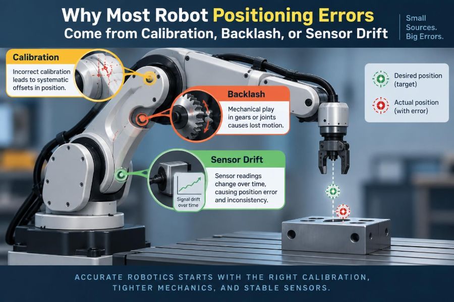
Three causes appear repeatedly: calibration errors, mechanical backlash, and sensor drift. Understanding how they differ gives engineers a faster path from “the robot missed” to a testable explanation and a durable correction.
🎯 Position Accuracy Is a System Property
A robot does not inherently know where its tool is. It estimates position from motor feedback, kinematic equations, calibrated coordinate frames, and sometimes external sensors such as cameras or laser scanners.
Positioning accuracy is therefore a system property. A highly accurate encoder cannot compensate for an incorrectly measured tool length, and an excellent camera cannot fully overcome a loose gearbox that moves differently depending on direction.
The commanded point, measured point, and actual physical point can all differ. Productive troubleshooting begins by identifying which comparison is failing.
📍 Accuracy, Repeatability, and Resolution Are Different
Accuracy describes closeness to the intended real-world location. Repeatability describes how consistently the robot returns to the same location. Resolution is the smallest increment the control system can distinguish or command.
A robot can be highly repeatable but inaccurate. For example, it may return to a point 0.4 mm away from the target every time because a work frame is shifted. Conversely, a robot with backlash can sometimes hit the target but show direction-dependent scatter.
| Observation | Likely interpretation |
|---|---|
| Same offset at many nearby targets | Frame, tool, or calibration error |
| Different result when approaching from opposite directions | Backlash, compliance, or control effects |
| Error grows during a shift or with temperature | Sensor drift or thermal change |
| Increasing error farther from a reference point | Scale, kinematic, or mapping error |
🧭 Coordinate Frames Create the Robot’s Spatial Vocabulary
Robots work by transforming coordinates between frames: the robot base, joints, flange, tool center point, workpiece, fixture, camera, and often a conveyor. A point that is correct in one frame can be wrong in another.
Suppose a vision system detects a hole center accurately in camera coordinates. The robot still needs a valid transformation from camera coordinates to robot-base coordinates. A small rotation error in that transformation produces larger lateral errors farther from the calibration area.
Many apparent motion problems are actually frame-definition problems. The robot is following its program correctly in the wrong spatial language.
🛠️ Tool Center Point Errors Move Every Task
The tool center point, or TCP, is the point the controller treats as the end of the robot’s working tool. For a gripper, it may be the grasp center. For a welding torch, it may be the effective tip. For a dispensing nozzle, it is often the outlet point.
If the TCP is measured incorrectly, every motion involving that tool inherits the error. An angular TCP error is especially deceptive: it may look minor near one orientation and become significant when the wrist rotates.
Tool changes deserve fresh verification. A nominally identical replacement gripper can differ because of assembly tolerances, bent fingers, altered jaw pads, or a mounting plate that did not seat fully.
🏗️ Work Frames Depend on Real Fixtures, Not CAD Ideals
A work frame describes where a part or fixture exists in the cell. CAD models are useful starting points, but fixtures in production can shift after maintenance, accumulate debris, or locate parts differently as clamps wear.
A common hypothetical case is a robot programmed from a fixture corner. If a technician replaces a locating pin and its centerline is slightly different, every pick or insertion referenced to that frame may shift together.
Reference features should be repeatable, accessible, and meaningful to the task. A decorative edge or flexible cover is a poor datum; hardened locating surfaces or deliberate calibration targets are usually better choices.
📐 Calibration Is Measurement, Not a One-Time Ritual
Calibration establishes the relationship between the robot’s mathematical model and the physical cell. It can include mastering axes, teaching TCPs, defining work frames, calibrating cameras, and aligning external axes.
The word can sound like a button press, but reliable calibration is a measurement process with uncertainty. Probe technique, target quality, operator consistency, sensor noise, and the number and distribution of points all influence the result.
A calibration result should be treated as evidence with a context: which tool, fixture, payload, temperature range, software version, and procedure produced it?
🧩 Kinematic Model Errors Hide Inside the Arm
A controller converts joint angles into tool position using a kinematic model: link lengths, joint-axis directions, joint offsets, and other geometry. The model is never a perfect copy of a physical machine.
Small geometric deviations may come from manufacturing tolerances, prior collisions, inaccurate axis mastering, or wear. Their effects can vary across the workspace, so a robot may pass a check near one pose while missing targets elsewhere.
Advanced kinematic calibration can improve absolute accuracy, but it requires sound measurement equipment and a suitable process. It is not a replacement for fixing a damaged reducer, loose joint, or unstable fixture.
🔁 Backlash Is Lost Motion During Reversal
Backlash is lost motion caused by clearance between mechanical components, such as gear teeth, couplings, screws, or belt drives. When direction reverses, the driving component must take up that clearance before the output responds fully.
Think of turning a steering wheel slightly before the wheels react. In a robot joint, the effect can make the same programmed coordinate produce different physical locations based on how the joint arrived there.
Backlash is not simply random error. Its direction dependence is a valuable diagnostic signature.
⚙️ Where Mechanical Play Enters a Robot System
Industrial robot arms often use reducers designed for low backlash, but no mechanism is immune to wear, damage, or compliance. Positioning systems also include components beyond the arm: linear rails, external rotary axes, end effectors, grippers, leadscrews, belts, and fixture clamps.
- Worn gear reducers or damaged gear teeth can introduce angular play.
- Loose couplings can make motor rotation and output motion disagree.
- Belt tension changes can affect axis response and repeatability.
- Gripper pivots and jaws can shift a part after the arm reaches position.
- Fixture clamps can allow a workpiece to settle under process force.
Locating the play matters. Re-teaching points may hide the symptom temporarily while the mechanical cause continues to worsen.
↔️ The Direction-Reversal Test Is Highly Informative
A simple diagnostic approach is to approach the same reference point from opposite directions or through different joint paths. Record the measured position rather than relying only on visual judgment.
If the difference changes predictably with approach direction, backlash or elastic compliance becomes more likely than a static work-frame offset. The test should use safe speeds and avoid introducing process loads that confuse the result.
For articulated robots, examine the joint configuration as well as Cartesian direction. Two paths that look similar at the tool can load joints and transmissions differently.
🧱 Compliance Is Not the Same as Backlash
Backlash involves clearance and lost motion. Compliance is elastic deflection under load. A long tool, flexible end effector, robot arm, fixture, or part can bend slightly even when there is no mechanical looseness.
A robot may position well in free space and miss during insertion, drilling, polishing, or dispensing because contact force changes its shape. Payload, acceleration, gravity direction, and cable forces can all alter deflection.
The remedy may involve lower acceleration, a stiffer tool, better support, force control, or a different approach strategy. Treating compliance as a coordinate error often creates a program that works in only one loading condition.
🧠 Servo Following Error Adds a Dynamic Layer
Servo systems continuously compare commanded and measured motor position. During rapid motion, the actual axis can lag slightly behind the command; this is called following error. A well-tuned system manages it within intended limits, but aggressive trajectories can expose limitations.
At the final settled position, following error may largely disappear. If errors occur only at speed, during corners, or before a process begins, timing and motion dynamics deserve attention.
Do not adjust servo gains casually to solve an apparent placement problem. Poor tuning can cause vibration, instability, or added wear. Use manufacturer procedures and qualified controls support.
🌡️ Temperature Changes Geometry and Electronics
Materials expand and contract with temperature, and electronic sensors can change behavior as they warm. A robot cell near ovens, weld operations, direct sunlight, or changing ambient conditions may show errors that correlate with thermal state.
Long rails, aluminum tooling, camera mounts, and robot structures can all move slightly as temperatures change. The relevant question is not whether thermal expansion exists, but whether it is large relative to the task tolerance.
A practical clue is time dependence: does the first part after startup differ from parts after the cell has run for an hour? Logging temperature alongside measurement results can reveal useful patterns.
📡 Sensor Drift Is a Slow Change in What “Measured” Means
Sensor drift is a gradual change in sensor output that is not caused by the corresponding real-world change. It can affect encoders, cameras, inertial sensors, force sensors, laser scanners, and analog measurement channels.
Drift may be thermal, electronic, optical, environmental, or age-related. It does not always mean the sensor is defective; every measurement system has limits, and some need periodic referencing or recalibration.
Unlike backlash, drift often appears as a smooth trend over time rather than a sudden difference between opposite approach directions.
👁️ Vision Systems Can Be Precise and Still Be Wrong
A camera can repeatedly identify a feature in pixel coordinates while producing an inaccurate robot correction. Lens distortion, focus changes, camera movement, lighting variation, calibration-target quality, and camera-to-robot transformation errors can all contribute.
Lighting deserves special attention. Reflections on metal, changing shadows, dirty lenses, and variable exposure can shift the apparent edge or center that an algorithm detects. A feature measurement is only as stable as the image evidence used to create it.
Check both stages separately: can the vision system measure a known target consistently, and can the robot transform that measurement into the correct physical action?
🧲 Encoders Measure Joints, Not Necessarily Tool Reality
Joint encoders report motion at a particular point in the drivetrain, often near the motor. They are excellent for closed-loop control, but they may not directly observe backlash, transmission flex, tool bending, or an object slipping in a gripper.
This distinction explains why a controller can report that all axes are at their targets while the tool is physically displaced. The feedback loop is faithfully controlling what its sensor observes.
External metrology, a dial indicator, a reference artifact, or a calibrated vision measurement may be needed to compare reported position with physical reality.
🧭 Mobile Robots Have a Different Drift Problem
For mobile robots, wheel encoders estimate travel from wheel rotation. Wheel slip, tire wear, uneven floors, debris, and changing payload can make odometry gradually diverge from the robot’s actual location.
Inertial measurement units add motion information but also accumulate errors over time. Cameras, lidar, landmarks, or docking targets can provide corrections, yet those sensors have their own calibration and environmental limitations.
The lesson is the same as for robot arms: local measurements must be periodically tied back to a trustworthy external reference.
🧪 Error Patterns Point to Different Causes
Before changing parameters, describe the pattern. Does the error have a fixed direction? Does it depend on position, orientation, speed, load, time, or approach direction? Patterns turn vague complaints into hypotheses.
- Fixed translational offset: suspect TCP, work frame, or fixture location.
- Error that increases with distance: suspect frame rotation, scale error, or camera calibration.
- Hysteresis after reversal: suspect backlash or changing friction.
- Load-dependent displacement: suspect compliance, payload settings, or gripping.
- Slow movement over hours or days: suspect drift, thermal changes, or fixture movement.
These are diagnostic clues, not proof. Several mechanisms can coexist in the same cell.
📏 Build a Measurement Plan Before Adjusting Anything
“It is off” is not an adequate measurement. Define the target feature, the coordinate frame, the measurement instrument, the acceptable tolerance, the robot pose, the payload, and the approach path.
Measure several repetitions at the same condition, then change one factor at a time. For example, compare clockwise and counterclockwise approaches while holding speed, tool, part, and reference artifact constant.
Measurement equipment also has uncertainty. A flexible ruler is not suitable for diagnosing a tight robot-placement tolerance; use a method capable of resolving the error you need to understand.
🗺️ Test Across the Workspace, Not at One Friendly Point
A single successful point can be misleading. Frame rotations, kinematic errors, and structural deflection often vary by location and orientation.
Create a compact verification pattern that samples the actual operating area: near and far positions, typical wrist orientations, and relevant heights. For a machine-tending task, include the approach pose and process pose rather than only an open-space point.
Workspace testing helps distinguish a global offset from a geometric model problem. It also prevents a local correction from silently degrading another part of the job.
🧷 Check the Part, the Gripper, and the Fixture
Not every positioning error is robot motion error. A part may sit differently in a nest, rotate slightly in gripper jaws, bend under clamping, or shift when a vacuum cup contacts an oily surface.
Verify the complete physical chain: part presentation, grasp confirmation, gripping force, jaw wear, cable or hose interference, fixture seating, clamp sequence, and datum contact. If the object moves after the robot reaches its point, coordinate changes will not solve the underlying issue.
Simple witness marks, reference pins, and before-and-after measurements can separate robot motion from part movement.
🧰 Recalibrate with Traceable Procedure Discipline
Recalibration is valuable when the diagnosis supports it. Use a documented procedure, clean reference surfaces, correct tools, stable environmental conditions where practical, and enough verification points to catch obvious mistakes.
Record the old and new values instead of overwriting history without review. A large unexpected change may reveal a damaged tool, a mounting issue, or an error in the recalibration process.
After calibration, independently validate the outcome on known physical features. A controller accepting calibration data does not prove that the task is accurate.
🧾 Version Control Belongs in the Robot Cell
Robot programs, frame values, TCP definitions, vision recipes, controller parameters, and calibration records are configuration data. Untracked edits make it difficult to identify when a positioning issue began.
Maintain backups and change records that state what changed, why, who approved it, and how it was verified. This discipline is especially useful when several shifts, integrators, or product variants share a cell.
A reliable baseline turns troubleshooting from memory-based debate into comparison against known-good data.
🛡️ Design Cells That Can Re-Reference Themselves
Good cell design makes verification easier. Include accessible reference artifacts, datum features that resist wear, rigid camera mounts, cable routing that does not pull on tools, and enough clearance to inspect mechanical components.
Some systems use routine checks against a fixed target, dock, gauge, or calibration plate. The purpose is not to eliminate all error automatically, but to detect changes before they affect many parts.
For demanding applications, independent measurement can be integrated into the process. The added complexity must be justified by the consequences of an undetected offset.
⏱️ Preventive Maintenance Protects Positioning Performance
Positioning quality can decline quietly as joints wear, fasteners loosen, belts age, lubrication changes, optics become contaminated, or fixtures experience repeated impacts. Maintenance should include checks tied to functional accuracy, not only whether the machine still runs.
Useful tasks may include inspecting tool mounts, checking fasteners to approved specifications, monitoring unusual noise or vibration, cleaning optics appropriately, reviewing robot alarms, and verifying reference positions after relevant service.
Maintenance intervals should follow equipment guidance, duty cycle, process loads, and observed condition. A high-force application and a light pick-and-place operation do not stress mechanisms in the same way.
🚫 Common Fixes That Mask the Real Problem
The fastest-looking fix is often to edit a point until a sample part passes. This can be reasonable for a confirmed, stable fixture shift, but it is risky when the cause is unknown.
- Do not compensate for backlash with arbitrary position offsets.
- Do not recalibrate a camera before checking whether its mount moved.
- Do not blame robot accuracy before proving the part is securely located.
- Do not tune controls to compensate for a loose mechanical connection.
- Do not validate only one successful cycle after a change.
Compensation has a place, particularly for known systematic effects. It should be documented, bounded, and verified rather than used as a substitute for diagnosis.
🔍 A Practical Fault-Isolation Sequence
When a robot misses its target, begin with safe observation and a narrow question: what exactly moved relative to what? Then work from stable, simple checks toward more complex model and control investigations.
- Confirm the error with a suitable physical measurement.
- Check part seating, gripping, tool mounting, and fixture condition.
- Compare repeated approaches from different directions and paths.
- Test representative points across the workspace.
- Review recent changes, calibration records, alarms, and environmental conditions.
- Verify frames, TCPs, and sensor calibration against known references.
- Escalate suspected drivetrain, servo, or structural issues through approved service procedures.
Lockout, guarding, reduced-speed modes, and site safety rules remain essential during any observation or measurement near robotic equipment.
🤝 Know When to Involve Specialists
Routine frame verification and basic mechanical inspection may be within a trained team’s responsibilities. Suspected reducer damage, axis mastering errors, safety-related configuration changes, servo tuning, or robot model calibration often require manufacturer-trained personnel or experienced integrators.
Escalation is not a failure of troubleshooting. It prevents an uncertain adjustment from creating a larger accuracy problem, equipment damage, or safety risk.
Bring useful evidence: measurement records, error patterns, program backups, screenshots or logs where permitted, photos of the setup, and details of recent changes.
🧭 The Core Principle: Trust the Physical Reference
Calibration, backlash, and sensor drift dominate many positioning problems because each breaks a different link between commanded coordinates and physical reality. Calibration corrupts the geometric relationship, backlash changes mechanical response, and drift changes the meaning of measurements over time.
The most effective response is not guessing which parameter to alter. It is comparing the robot’s reported state with a stable physical reference, then using the error pattern to isolate the weak link.
A robot can only be as accurate as its model, mechanics, measurements, and references allow. When those elements are checked systematically, positioning problems become engineering problems with evidence—not mysteries hidden in a program.
Reliable robot positioning comes from maintaining agreement between coordinates, mechanics, sensors, and the real world they are meant to describe. 🦾📏🔧