
A robotic arm picks up a small component from a conveyor belt, turns, and places it into a fixture. The motion looks simple. Yet the component may arrive a few millimetres away from its expected position, the arm may flex slightly under load, and a warm motor may behave differently from a cold one.
Without correction, tiny discrepancies accumulate. The gripper misses the part, presses too hard, or places it just far enough off target to cause a later assembly step to fail.
Humans solve this kind of problem almost automatically. We look at a cup, move our hand, notice if we are slightly off, and adjust before touching it. Robot feedback control gives machines a version of that ongoing correction process.
It is one of the reasons robots can move reliably in factories, operate steadily in a surgical setting, balance on uneven ground, and keep a drone from drifting in a gust of wind. Precise motion is not merely about commanding a motor; it is about measuring what actually happened and responding intelligently.
🎯 Precise Movement Is More Than Reaching a Position
A robot motion command usually describes a desired outcome: rotate a joint to an angle, drive a wheel at a speed, hold a camera level, or guide an end effector along a path. Precision means the real motion stays acceptably close to that desired outcome over time.
That distinction matters because a robot can reach the correct final position while still moving poorly. It may overshoot, vibrate, arrive too slowly, collide with a delicate object, or deviate from a path during travel.
For many tasks, the controlled quantity is not position alone. Engineers may need to control velocity, acceleration, torque, contact force, pressure, temperature, or a combination of these variables.
🔄 The Basic Idea of Feedback Control
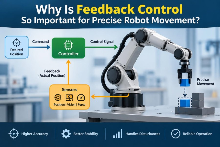
Feedback control is a process in which a controller compares a measured output with a desired reference, calculates the difference, and changes the actuator command to reduce that difference.
In a joint-position system, the reference may be 45 degrees and the measured joint angle may be 42 degrees. The difference is the error. The controller commands the motor to move further, then checks again repeatedly.
This loop can run many times per second. The robot does not assume its earlier command worked perfectly; it continually asks, in effect, “Where am I now, and what correction is needed?”
📡 The Closed Loop Behind Reliable Motion
A feedback-controlled robot is called a closed-loop system because measurements from its output return to influence future commands. The loop contains four essential roles: a reference, sensors, a controller, and actuators.
- Reference: the target state or planned trajectory.
- Sensors: devices that measure the actual state.
- Controller: logic that turns error into a command.
- Actuators: motors, valves, or other devices that create physical motion.
The physical robot and its surroundings are often called the plant. Their behavior is never perfectly fixed, which is exactly why the loop is valuable.
📤 Open-Loop Control Has a Useful but Limited Role
In open-loop control, a system sends a command without using output measurements to correct the result. A simple timer-based motor command is an example: apply power for two seconds and assume the mechanism moved as expected.
This can be appropriate when conditions are predictable and the consequence of error is small. A low-cost dispenser, for example, may run a motor for a calibrated duration without measuring every rotation.
But if friction changes, a battery voltage drops, or a load becomes heavier, the same command produces a different result. Open-loop control cannot recognize that discrepancy on its own.
🧭 Sensors Give a Robot a Sense of Its Actual State
Feedback quality depends on what the robot can measure. Rotary encoders report motor or joint rotation; linear encoders measure travel along a rail; inertial measurement units estimate angular motion and acceleration; cameras observe objects and landmarks.
Other sensors matter when robots interact with the physical world. Force-torque sensors can measure contact loads, current sensors can provide a rough indication of motor torque, and tactile sensors can detect pressure at a gripper.
A sensor does not directly create accuracy. It provides evidence about reality. The controller must interpret that evidence quickly enough and accurately enough to make a useful correction.
📏 Error Is the Signal That Drives Correction
Control error is commonly written as the desired value minus the measured value. If a mobile robot should travel at 1 metre per second but its measured speed is lower, a positive speed error tells the controller more drive effort may be needed.
Error can be a single number, but complex robots often track many errors at once. A six-axis arm may have joint-angle errors for each axis, while a vision-guided task also considers the difference between the observed and desired object location.
The goal is not always to make every measured error exactly zero. Sensor noise, mechanical compliance, safety constraints, and changing targets make that unrealistic or undesirable. The practical goal is stable, repeatable performance within the task’s required tolerance.
⚙️ Actuators Never Behave Like Perfect Commands
A motor command is not the same thing as motion. Motor torque varies with current, speed, temperature, supply voltage, gearing, and control electronics. Pneumatic and hydraulic actuators add pressure dynamics, valve delays, and fluid effects.
Even a well-designed mechanical system has friction, backlash, elasticity, and inertia. Backlash is lost motion caused by clearance between mechanical parts, such as gear teeth changing direction before fully engaging.
Feedback compensates for many of these effects as they appear. It does not eliminate the underlying physics, but it helps the robot produce the intended result despite it.
🧱 Loads and Payload Changes Disturb Motion
A robot arm moving an empty gripper does not behave exactly like the same arm carrying a heavy tool. The payload changes inertia, gravitational torque, and sometimes structural flex.
Consider a warehouse robot lifting a bin. A motor command that accelerates an empty lifting platform smoothly may be inadequate when the bin is full. Position feedback detects the slower-than-expected movement, allowing the controller to increase its effort within safe limits.
Payload variation is one reason calibrated motion profiles alone are often insufficient. Feedback adapts to the result rather than relying entirely on an assumed load.
🌬️ External Disturbances Are Normal, Not Exceptional
Robots operate in environments full of disturbances: a floor seam redirects a wheeled platform, a person bumps a collaborative arm, wind pushes a drone, or a cutting tool encounters harder material.
A disturbance changes the system’s actual state. Feedback sees the resulting deviation and directs the actuator toward recovery. The faster and more appropriately it reacts, the less the disturbance affects the task.
Not every disturbance can be fully rejected. A strong push may exceed available motor torque, and a camera may temporarily lose its target. Good engineering includes both feedback correction and safe behavior when correction capacity is limited.
🧮 Proportional Control Provides Immediate Response
The simplest common rule is proportional control: command an effort proportional to the current error. A large position error produces a stronger command; as the robot nears target, the command decreases.
This is intuitive and often useful, but proportional control alone has trade-offs. A low gain can make motion sluggish and leave noticeable error under load. A high gain can make the system overshoot or oscillate.
Gain is the multiplier connecting error to corrective action. Choosing it is not a matter of selecting the largest possible number; it requires balancing responsiveness against stability.
🧩 PID Control Adds Memory and Anticipation
PID control combines proportional, integral, and derivative terms. It is widely used because these three actions address different aspects of tracking performance.
| Term | What it responds to | Typical contribution |
|---|---|---|
| Proportional (P) | Current error | Provides direct corrective effort |
| Integral (I) | Accumulated past error | Helps remove persistent offset |
| Derivative (D) | Rate of error change | Can add damping and reduce overshoot |
For example, a joint that consistently stops slightly short because gravity pulls on it may benefit from integral action. Derivative action can help a fast-moving joint slow before it swings past its target.
PID is powerful, not magical. Its gains must be tuned for the mechanism, sensing quality, operating range, and safety constraints.
📉 Stability Matters More Than Aggressive Correction
A stable control loop settles toward its target after a change or disturbance. An unstable loop amplifies deviations, often producing growing oscillations or erratic motion.
Imagine steering a cart down a line. If each small leftward deviation prompts an excessively sharp right turn, the cart crosses the line, receives another excessive correction, and repeatedly weaves farther away. Robot joints can behave similarly.
Feedback is therefore important not just because it corrects error, but because it can correct error in a controlled manner. Stability analysis and cautious testing are central parts of motion-system design.
⏱️ Timing and Latency Shape Control Quality
Feedback has to arrive in time. Latency is the delay between an event, sensing it, calculating a response, and applying that response. Excessive delay makes a controller act on an outdated picture of the system.
A slow loop may work for a room-temperature controller but fail for a rapidly moving drone or robot arm. Sampling rate, communication delays, computation time, filtering, and actuator response all contribute to the loop’s effective timing.
Faster is not automatically better. A higher update rate can expose more measurement noise and consume more computing resources. The required bandwidth should match the dynamics of the task being controlled.
🔊 Sensor Noise Requires Careful Filtering
Real measurements contain noise from electronics, vibration, quantization, lighting variation, and other sources. If a controller reacts strongly to every tiny fluctuation, it can command unnecessary motor activity or become unstable.
Filtering smooths measurements, but filtering also introduces delay. This creates a practical compromise: remove enough noise to avoid false corrections without delaying genuine corrections too much.
Derivative control is particularly sensitive because it depends on how quickly a signal changes. Engineers frequently filter derivative estimates or use measurement structures that avoid amplifying high-frequency noise.
🗺️ Trajectory Tracking Controls Motion Between Endpoints
Many robot tasks require following a time-based path rather than simply reaching a final point. Welding, dispensing adhesive, camera stabilization, and machining all depend on what happens along the way.
A trajectory specifies desired position, velocity, and sometimes acceleration at successive moments. Feedback compares the actual motion with this moving reference and corrects deviations continuously.
Trajectory tracking also makes motion gentler. Instead of abruptly asking a joint to jump to a new angle, a planner can provide a smooth profile that respects acceleration and jerk limits. Jerk is the rate at which acceleration changes.
🦾 Joint-Space and Cartesian Feedback Solve Different Problems
Joint-space control regulates each motorized joint directly. It is common because encoders naturally measure joint angles and because each actuator can be controlled close to its hardware.
Cartesian control focuses on the end effector’s position and orientation in workspace coordinates. This is useful when the important instruction is “move the tool straight down” rather than “rotate joint two by this amount.”
Cartesian motion still depends on joints. Robot kinematics converts the desired tool motion into joint commands, while feedback at one or both levels helps manage the difference between planned and actual movement.
👁️ Vision Feedback Helps When the World Is Not Fixed
A conventional robot program may assume a part is always in the same fixture. In practice, a part can shift, a conveyor can vary slightly, or an object may arrive at an unknown orientation.
Visual servoing uses camera measurements as feedback. The robot can adjust its tool motion based on an object’s observed position, orientation, or image features.
Vision introduces its own challenges: camera calibration, lens effects, changing illumination, occlusion, and processing latency. It is especially useful when variability is too large for a preprogrammed coordinate alone, but it needs robust failure handling when the target cannot be seen.
🤝 Force Feedback Makes Contact Tasks Safer and More Capable
Position control works well while a robot moves through free space. Once it contacts an object, continuing to force a position can create unexpectedly high loads if the object is not exactly where the model predicted.
Force control adjusts motion or actuator effort based on measured contact force. A polishing robot can maintain a desired pressing force as a surface height changes. A gripper can close until it reaches an appropriate force rather than crushing a fragile item.
Many systems use impedance control, which makes robot motion behave as if a virtual spring and damper exist between the tool and its target. This can make contact feel compliant instead of rigid.
🧍 Human-Robot Interaction Needs Compliant Behavior
Robots that share space with people need more than accurate coordinates. They need predictable responses to contact, changing loads, and uncertain human motion.
Force sensing, torque limits, compliant mechanisms, collision detection, and appropriate control settings can reduce contact forces and help a robot stop or yield when needed. These features support safer interaction, but they do not replace a complete risk assessment and suitable safeguarding.
A controller tuned for maximum rigidity in an isolated machining cell may be inappropriate for a robot handing objects to a person. The task context changes what “good control” means.
🚁 Balancing Robots Show Feedback at Its Fastest
A self-balancing robot must continually correct its posture because gravity pulls it away from upright equilibrium. Its inertial sensors estimate tilt and angular velocity, and the controller drives the wheels to move underneath the falling body.
The same principle appears in quadcopters. Sensors estimate orientation and motion; the controller changes individual rotor thrusts to counter tilt, drift, and disturbances.
These examples make feedback easy to see: without ongoing measurement and correction, the system quickly loses the state it is trying to maintain.
🏭 Industrial Repeatability Depends on More Than Feedback
In industrial automation, feedback supports repeatable motion, but precision also depends on calibration, rigid mechanics, appropriate gearboxes, accurate fixtures, and reliable programming.
An encoder may report that a motor shaft reached its requested angle while the tool tip is displaced by flex, gear clearance, or thermal expansion. This is why high-accuracy systems sometimes use external measurement, tool-center-point calibration, or compensation models.
Feedback improves what the system measures. If the measurement does not represent the task-critical location, engineers may need additional sensing rather than simply retuning the controller.
🧠 Feedforward Complements Feedback
Feedback reacts after a difference is measured. Feedforward control uses a model or known information to command useful action in advance.
For a robot arm, the controller may estimate the torque needed to hold a link against gravity before an error becomes large. It can also account for planned acceleration and expected payload inertia.
The strongest motion systems often combine both approaches. Feedforward provides a good initial command; feedback corrects model errors, unmeasured disturbances, and changing conditions.
🧪 System Models Improve Performance but Have Limits
A dynamic model represents how forces, mass, inertia, friction, and geometry influence robot motion. Better models can improve tracking, reduce lag, and lower the amount of corrective feedback needed.
However, models are approximations. A cable may flex differently over time, friction may vary across a joint’s range, and a payload may not be exactly known. Overreliance on a model can create poor behavior when reality differs from assumptions.
Feedback provides resilience to such mismatch. Model-based control and measurement-based correction are partners, not competing philosophies.
🛠️ Tuning Is a Structured Engineering Task
Controller tuning means selecting gains and related settings that deliver acceptable behavior. Engineers typically begin with clear performance requirements: allowable error, settling time, overshoot, load range, noise level, and safety limits.
A sensible workflow is to test at low energy, observe measured responses, and change one well-understood setting at a time. Simulation can help reveal likely issues, but hardware testing remains necessary because physical systems contain unmodeled effects.
- Check sensor direction and units before increasing gains.
- Test representative payloads, speeds, and directions.
- Record position, velocity, current, and error signals where possible.
- Apply torque, speed, travel, and emergency-stop limits during experiments.
Tuning by trial alone can be slow and risky. Measurements turn subjective impressions such as “it seems shaky” into observable behavior.
⚠️ Common Feedback-Control Mistakes
One frequent error is assuming oscillation means the robot needs more gain. Often the opposite is true, or the problem may be delay, backlash, flexible structure, noisy sensing, or an unsuitable control architecture.
Another is ignoring actuator saturation. A controller may demand more torque than a motor can provide. If integral action continues accumulating during saturation, the stored correction can cause a large overshoot when the actuator recovers. This is called integral windup.
Other practical mistakes include using an encoder resolution that is too coarse, filtering a signal without accounting for the added delay, and tuning only under ideal no-load conditions.
🛑 Safety Functions Must Not Depend on Perfect Tracking
Feedback reduces tracking error, but it cannot guarantee that every sensor, processor, cable, actuator, or software component will behave correctly. A safe robot system needs independent layers such as limit switches, current limits, physical stops, protective monitoring, emergency-stop circuits, and appropriate safety-rated functions where required.
Control software should also detect implausible measurements and communication loss. If a joint reports impossible speed or a critical sensor disappears, the correct response may be a controlled stop rather than continued correction.
Precision and safety are linked, but they are different design objectives. Treating a normal control loop as the only safety barrier is a serious engineering mistake.
📊 Measure the Right Performance Indicators
A robot can look smooth while missing the requirement that matters. Evaluation should match the application: path error for dispensing, force regulation for insertion, settling time for pick-and-place, or orientation stability for a camera platform.
Useful indicators may include steady-state error, peak overshoot, response to disturbances, repeatability over cycles, energy use, motor temperature, and contact-force peaks. The acceptable balance varies by application.
For instance, a very fast response may be valuable on a high-throughput line, yet a slower and more compliant response may be preferable when handling fragile products.
🔧 Design Mechanics and Control Together
Control software cannot fully compensate for poor mechanical design. Excessive gear backlash, flexible mounting, loose belts, undersized actuators, and poorly routed cables can limit achievable precision.
Conversely, a mechanically excellent robot can still perform poorly with inadequate sensing or poorly tuned control. The most effective approach treats structure, actuators, transmissions, sensors, electronics, and algorithms as one connected system.
Early design choices have lasting consequences. Adding a high-resolution sensor or stiffening a critical bracket may solve a problem more cleanly than trying to fix everything through increasingly complicated code.
🧭 A Practical Way to Choose a Control Strategy
Start with the task rather than with a favorite algorithm. Ask what must be controlled, what disturbances are likely, how quickly the state changes, and what happens if the robot is wrong.
A slow positioning stage may need encoder feedback and a carefully tuned position loop. A drone needs fast attitude feedback. An assembly robot inserting a peg may need both position guidance and force-sensitive compliance.
Then select sensors that observe the task-critical variables, choose actuators with sufficient authority, and validate performance across the expected operating envelope. Simpler control is often preferable when it meets the requirement reliably.
🌟 The Core Principle: Measure, Compare, Correct
Feedback control is essential because robot commands encounter an imperfect physical world. Components wear, loads change, models have gaps, sensors have limits, and outside forces interfere with motion.
By measuring actual behavior, comparing it with a goal, and applying stable corrections, a robot can remain accurate enough for useful work. The same principle scales from a motor holding a shaft angle to a vision-guided arm, a balancing vehicle, or a force-controlled surgical instrument.
The most capable systems do not pretend uncertainty is absent. They sense it, manage it, and respond within well-designed performance and safety boundaries.
Precise robot movement comes from closing the gap between what a robot was told to do and what it is actually doing. That ongoing conversation between sensors, controller, actuators, and mechanics is what turns a command into dependable motion. 🦾📡⚙️