
A robot arm reaches for a connector, stops just beside it, and then makes a tiny corrective move. On a factory line, that hesitation may be barely visible. In a laboratory, it can mean a missed vial, a damaged sample, or a failed insertion.
The surprising part is that the robot may have received the correct command. Its controller knows the target coordinates, its encoder reports motion, and the program runs exactly as written. Yet the tool center point—the working point at the end of the arm—does not always land where the software expects.
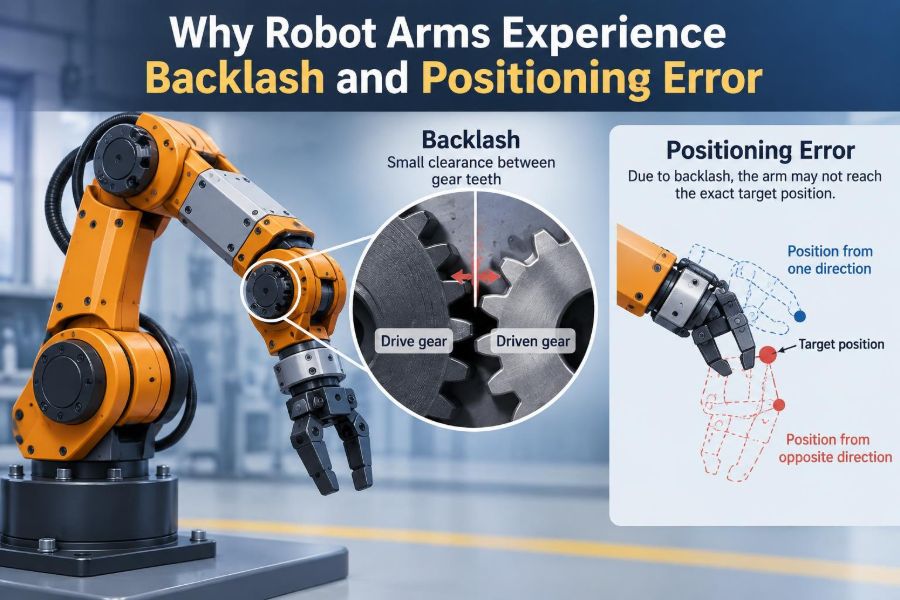
Two closely related reasons are backlash and positioning error. Backlash is unwanted lost motion when a mechanism reverses direction. Positioning error is the broader difference between the commanded, measured, and actual physical position.
Understanding the distinction helps engineers diagnose problems rather than merely slowing a robot down or changing numbers until a demonstration looks acceptable. It also explains why a robot that repeats a task well can still be inaccurate in absolute space.
🎯 The Difference Between Accuracy and Repeatability
Accuracy describes how close the robot reaches a commanded physical location. Repeatability describes how consistently it returns to the same location under the same conditions. These are related, but they are not interchangeable.
A robot can repeatedly stop 0.5 mm from a target. That is poor accuracy but good repeatability. Calibration can often correct a stable offset; variable backlash, thermal drift, and changing loads are harder because they make the error depend on the path taken.
🔁 What Backlash Actually Means
Backlash is the free movement between mating components before torque transfers after a reversal. Imagine turning a worn steering wheel slightly left, then right: for a brief moment, the wheel moves but the road wheels do not respond.
In a robot joint, the motor may rotate while clearance is being taken up between gear teeth, a gearbox output, a belt and pulley, or another transmission element. The encoder can honestly report motor motion even though the arm link has not yet moved.
⚙️ Why Gear Teeth Need Clearance
Perfectly zero clearance sounds ideal, but real gears need practical running clearance. Manufacturing variation, lubrication, thermal expansion, and tooth geometry make a tightly forced mesh prone to friction, heat, noise, or binding.
Designers therefore balance low backlash against efficiency, cost, durability, and tolerance to contamination. Some precision mechanisms use preload to remove clearance, but preload also raises friction and can increase wear or motor torque requirements.
🪥 Spur, Helical, and Planetary Gear Sources
Conventional gear trains are a common origin of backlash. In a simple pair of gears, clearance exists between tooth flanks. Multiple stages can make the final angular play more noticeable at the output, especially where reductions are large.
Helical gears can run more smoothly because several teeth may share load, but they do not automatically eliminate backlash. Planetary gearboxes are compact and strong for their size, yet their internal clearances, carrier behavior, and assembly tolerances still affect reversal performance.
🌀 Harmonic Drives and Their Trade-Offs
Many articulated industrial arms use strain-wave, often called harmonic, drives because they offer high reduction in a compact package and can have very low backlash when new. A flexible spline is deformed to engage teeth progressively, rather than relying on an ordinary gear pair alone.
“Low backlash” does not mean “zero positioning error.” Elastic deformation, torsional compliance, wear, load-dependent deflection, and transmission error can remain. A drive choice must be judged in the complete joint, not from one catalog specification.
🧭 Backlash Appears Most Clearly During Reversal
Backlash is directional. If a joint approaches a point from the same direction every time, clearances tend to settle on the same side and the result may look stable. Reverse the joint, and the output can lag until the gap is closed.
This is why a robot may pass a simple point-to-point test but fail a task involving zigzags, contour following, or alternating pick locations. The route to the target matters, not only the target itself.
📐 Small Joint Errors Become Large Tool Errors
An angular error at a shoulder or elbow joint moves every structure beyond that joint. The farther the tool center point is from the joint, the larger the resulting linear displacement can be.
For small angles, a useful approximation is linear error equal to lever-arm length multiplied by angular error in radians. A tiny rotational gap at a long-reach joint can therefore shift a gripper enough to matter during insertion or inspection.
🦾 Error Accumulates Along a Kinematic Chain
A serial robot arm is a chain: base, shoulder, elbow, wrist, and tool. Each joint has its own geometric offsets, compliance, encoder uncertainty, and transmission behavior. The final pose combines all of them.
Errors do not always simply add in one direction; their effects depend on arm posture. Still, several modest imperfections can produce a substantial tool error, particularly near a stretched configuration where some directions are mechanically sensitive.
📍 Encoder Position Is Not Always Link Position
Most servo systems use encoders to close a position loop. A motor-side encoder measures motor shaft angle extremely well, but it cannot directly detect clearance or twist occurring after the sensor in the drivetrain.
Output-side encoders measure closer to the actual joint motion and can reveal some transmission effects. They add cost and integration complexity, but they are valuable when precise output position matters more than merely precise motor motion.
🧱 Structural Compliance Creates Deflection
Even with no measurable backlash, robot links, gearboxes, bearings, mounts, and end effectors bend slightly under load. This is compliance: the opposite of stiffness. The arm may reach a coordinate unloaded, then sag or twist when it carries a part.
Compliance is continuous rather than a distinct gap. That difference matters in diagnosis: backlash often produces a directional dead zone, while elastic deflection changes progressively with force and can recover when the load is removed.
🏋️ Payload, Reach, and Gravity Matter
A payload generates torque around upstream joints, and torque rises with distance from the joint. The same gripper can be acceptable close to the robot body but cause visible droop near maximum reach.
Gravity compensation in the controller helps motors generate appropriate holding torque. It cannot make flexible metal, bearings, or gear teeth infinitely stiff. Payload ratings should be treated as operating limits, not promises of equal precision across every pose.
🏃 Dynamic Motion Adds Following Error
During acceleration, the motor must overcome inertia, friction, and load torque. If the servo cannot follow the commanded trajectory perfectly, the difference is called following error.
At a stop, a well-tuned controller may reduce most of this error. During fast path motion, however, it can affect contour accuracy. High speed, abrupt corners, a heavy tool, or a poorly tuned control loop can make a static calibration look less effective.
🌡️ Temperature Changes Mechanical Geometry
Motors warm, gearboxes warm, and long links expand or contract with temperature. Lubricant viscosity also changes, affecting friction and the torque needed to begin or reverse movement.
These effects are often gradual, which makes them easy to overlook. A robot calibrated cold may behave differently after sustained operation. Warm-up routines, temperature-aware compensation, and calibration under representative conditions can reduce surprises.
🛢️ Friction, Stiction, and Lubrication Effects
Static friction, sometimes called stiction, is the resistance that must be overcome to start motion. Once moving, friction may decrease or change character. Near a target, this can lead to stick-slip motion or small settling movements.
Old lubricant, inappropriate grease, contamination, seal drag, and corrosion can worsen this behavior. Friction is not backlash, but the two can look similar when a robot makes small reversals, so testing must separate them carefully.
🔩 Bearings, Belts, and Fasteners Can Add Play
Not all lost motion comes from gear teeth. Worn or improperly preloaded bearings can permit radial or axial movement. Belt drives can stretch, tooth engagement can shift, and couplings can twist under torque.
A loose mounting bolt or flexible fixture can imitate a joint problem because the tool moves relative to the workpiece. Inspection should follow the complete force path from robot base through the tool, fixture, and part support.
🧮 Kinematic Model Errors Shift Every Target
The controller converts a Cartesian target into joint angles using a kinematic model. That model contains link lengths, joint axes, offsets, and tool coordinates. If any value differs from the physical robot, commanded geometry and real geometry diverge.
A slightly misplaced joint axis or an incorrectly entered tool center point can create position errors that remain even with excellent transmissions. This is why mechanical repair alone cannot cure every accuracy complaint.
🧰 Tool Center Point Errors Are Common
The tool center point, or TCP, is the reference point used for the working end of a tool. For a gripper, it may be between fingertips; for a welding torch, it may be near the electrode tip; for a camera, it may be an optical reference.
If the TCP is measured poorly, every programmed point is offset. A bent tool, changed jaw, replaced cutter, or slightly rotated tool flange can invalidate a previously correct TCP calibration.
🧭 Base Frames and Work Frames Also Matter
Robot coordinates are meaningful only relative to coordinate frames. The base frame locates the robot; a work frame locates the fixture or cell; a tool frame locates the end effector.
A shifted fixture, an unlevel robot pedestal, or a work frame taught from the wrong feature produces systematic error. These errors can resemble backlash until a direction-reversal test shows that the result does not depend strongly on approach direction.
📊 A Practical Error Signature Guide
| Observed behavior | Likely contributor | Useful check |
|---|---|---|
| Different result after opposite approaches | Backlash or hysteresis | Approach the same point from both directions |
| Error increases with payload or reach | Compliance or gravity deflection | Compare unloaded and loaded poses |
| Error grows at high speed | Following error or tuning limits | Repeat the path at reduced speed |
| Same offset everywhere | Frame, TCP, or model error | Verify calibration references |
| Drift during a long shift | Thermal or wear-related change | Log behavior from cold to warm |
These patterns are clues, not final diagnoses. Several mechanisms can exist simultaneously, and a valid test changes one variable at a time.
🔍 Test Directional Lost Motion Safely
A useful diagnostic is to command a joint or Cartesian point to approach a reference slowly from opposite directions. A dial indicator, displacement sensor, vision system, or carefully arranged mechanical reference can reveal whether the final location differs.
Keep the test at safe speeds, away from collisions, and within the manufacturer’s procedures. Do not push, pull, or restrain a powered robot by hand unless its safety mode, brakes, and risk controls explicitly allow that action.
📏 Measure at the Point That Matters
Measuring motor motion cannot establish where a nozzle, probe, or gripper fingertip truly is. Whenever possible, measure displacement at the TCP or at the functional feature that determines process quality.
For example, a machine-vision calibration target may reveal image-space error, while a precision gauge pin may reveal insertion alignment. Choose a measurement method whose resolution and uncertainty are appropriate for the tolerance being evaluated.
🧪 Separate Repeatability Tests From Accuracy Tests
To test repeatability, move to the same target repeatedly using the same approach and compare the cluster of final positions. To test accuracy, compare those positions with an independently known physical reference.
Then repeat with alternate approaches, loads, temperatures, and speeds. This staged approach prevents a common mistake: calling a robot “accurate” merely because it returns consistently to a point that was taught using its own imperfect coordinate system.
🧠 Calibration Can Correct Stable Errors
Calibration can update TCP values, work frames, joint offsets, and—in more advanced systems—kinematic parameters. It is especially effective for predictable, repeatable geometric error.
However, calibration cannot remove a changing mechanical gap. A compensation table may improve a known directional error in a narrow operating range, but it should not be used to hide a worn gearbox, loose joint, or unsafe degradation.
🧩 Software Compensation Has Limits
Controllers can apply backlash compensation by commanding extra motion when direction changes, or use load and gravity models to improve pose prediction. These methods can be useful when the mechanism is stable and well characterized.
They become less reliable when clearance varies with torque, temperature, location, or wear. Compensation also cannot restore stiffness: if external contact force bends the arm, software cannot know the exact deflection without suitable sensing and a valid model.
🛠️ Mechanical Design Choices Reduce Sensitivity
Precision begins with architecture. Shorter lever arms, stiff links, rigid mounting, appropriate bearing preload, low-backlash transmissions, and a compact tool all reduce the ways a small joint disturbance reaches the task.
Designers should also consider where precision is needed. A large arm may place a part roughly, while a small, stiff local axis or compliant insertion device handles the final millimeters. The best solution is not always a more expensive gearbox.
🧲 External Sensing Closes the Reality Gap
Vision cameras, force-torque sensors, laser sensors, and external metrology can provide information that internal encoders cannot. A camera can locate a shifted part; a force sensor can detect contact and guide an insertion.
External sensing introduces its own calibration, latency, lighting, and noise challenges. Still, for variable environments, it often delivers more robust results than trying to make open-loop geometric perfection solve every uncertainty.
🤝 Compliance Can Sometimes Be Useful
Compliance is usually undesirable for pure positioning, but controlled compliance can protect parts during assembly. A remote-center-compliance device, force-controlled wrist, or carefully designed flexure can help a peg find a hole despite small alignment errors.
This is not a substitute for sound alignment. Excessive compliance can reduce path quality and hide a worsening mechanical issue. Its value comes from matching the robot’s behavior to a contact task with known, managed forces.
⚠️ Common Troubleshooting Mistakes
- Changing speed first: slower motion may hide dynamic error while leaving backlash untouched.
- Retouching every point: this can mask a bad frame, TCP, or mechanical fault and makes future maintenance harder.
- Testing only one approach: directional behavior is central to identifying backlash.
- Ignoring the fixture: a moving workholding system can look exactly like robot inaccuracy.
- Using compensation before inspection: loose components and abnormal wear need mechanical evaluation.
🗓️ Maintenance Is Part of Position Control
Position quality depends on inspection and maintenance as well as programming. Follow the robot manufacturer’s intervals for lubrication, joint inspection, brake checks, fastener torque procedures, and gearbox evaluation.
Trend measurements over time rather than relying on memory. A small baseline test at a critical production pose can reveal gradual change before it becomes a quality problem or leads to an unexpected collision.
📋 Specify the Right Performance Requirement
When selecting or integrating a robot, ask whether the task needs repeatability, absolute accuracy, path accuracy, orientation accuracy, contact sensitivity, or all of these. A catalog repeatability figure alone does not define performance in a real cell.
State the payload, reach, speed, temperature range, tool geometry, fixture tolerance, and measurement method. A requirement such as “place within tolerance at the functional feature under production load” is more actionable than a vague demand for precision.
🧭 The Core Principle: Follow the Entire Error Chain
Backlash is a mechanical clearance problem, but positioning error is a system problem. Commands pass through a controller, sensors, transmissions, joints, links, tools, coordinate frames, fixtures, and the process itself.
The most reliable diagnosis follows that chain and looks for a recognizable pattern: direction dependence suggests lost motion; load dependence suggests compliance; speed dependence suggests dynamics; constant offsets suggest calibration or geometry. Treating the symptom without identifying the pattern wastes time.
A robot arm reaches its best practical precision when its mechanics, sensing, calibration, control settings, tooling, and fixture are evaluated as one connected system—not as isolated parts. That systems view turns mysterious misses into measurable engineering problems. 🦾📐🔧