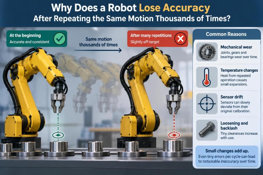

A robot on a production line may place parts perfectly at the start of a shift, then begin missing a tight tolerance hours later. The change can be subtle: a bead of adhesive moves toward one edge, a screw driver no longer meets its fastener cleanly, or a camera inspection reports an increasing number of borderline parts.
This is confusing because the robot is running the same program, at the same speed, through the same points. Unlike a human operator, it does not get tired in the usual sense. Yet repeatability can degrade, and the effect can eventually become a quality, downtime, or safety problem.
The explanation is rarely one dramatic failure. More often, many small physical and control-system effects accumulate until the real machine no longer behaves exactly like the mathematical robot described in its program.
Understanding those effects helps engineers troubleshoot intelligently, specify preventive maintenance, and decide whether the right remedy is recalibration, repair, process redesign, or a better measurement system.
🎯 Accuracy and Repeatability Are Different Measurements
Accuracy is how close a robot reaches the intended real-world position. Repeatability is how consistently it returns to the same position when commanded to repeat a motion.
A robot can be highly repeatable but inaccurate. For example, it may return to a point that is 0.5 mm away from the programmed target every time. Conversely, a robot affected by vibration may have an average position near the target while scattering around it from cycle to cycle.
When people say a robot has “lost accuracy,” they should first ask whether its average position shifted, its variation increased, or both. Those patterns point to different causes.
📍 The Program Commands a Model, Not the Physical World
A robot controller calculates joint angles from a geometric model: link lengths, joint axes, motor encoder readings, tool dimensions, and coordinate frames. This process is called kinematics.
The real arm is not perfectly rigid, perfectly assembled, or permanently unchanged. A controller can execute its calculations flawlessly while the actual tool tip lands somewhere else because the machine behind the model has changed.
Think of a map route that remains correct while a bridge settles slightly or a road closes. The instructions have not changed, but the physical conditions that made them reliable have.
🔁 Why Repetition Reveals Small Errors
One cycle may not expose a tiny error. A process can tolerate it, measurement noise can hide it, and the robot may happen to approach the point from a favorable direction.
Thousands of cycles apply the same loads, reversals, accelerations, heat input, and cable flexing again and again. Repeated motion can turn a barely noticeable clearance or thermal shift into a measurable process drift.
Repetition also makes patterns easier to see. A defect appearing only after a long run is useful evidence: it suggests temperature, wear, contamination, or a changing production condition rather than a static programming mistake.
🧭 Joint Backlash Creates Direction-Dependent Position Error
Backlash is unwanted free movement between mechanical elements, such as gears, reducers, splines, or drive components. Before torque transfers fully after a reversal, one component can move through a small clearance.
As backlash grows, a joint can settle in a slightly different position depending on whether it approached from the positive or negative direction. The tool may therefore reach the “same” Cartesian point differently on alternating paths.
This is especially troublesome in insertion, dispensing, and machining tasks. A point taught from one approach direction may not be reproduced when the production path arrives from another.
⚙️ Gearbox Wear Changes the Robot’s Real Geometry
Many industrial robots use precision reduction mechanisms to convert motor motion into high joint torque. Their bearings, teeth, rolling elements, and lubricated contact surfaces operate under repeated load.
Wear does not always produce obvious looseness at first. It may appear as increased compliance, a changed friction profile, or lost stiffness under load. A robot can look acceptable when moving freely but deflect enough to affect a process once it pushes, cuts, presses, or carries a payload.
Wear rate depends strongly on load, acceleration, duty cycle, shock events, lubrication condition, and the joint’s orientation. A heavily used wrist joint often deserves closer attention than a lightly loaded base axis.
🧱 Structural Flex Means Position Depends on Load
Robot links, wrists, fixtures, pedestals, and end effectors all flex slightly. This is normal engineering behavior, not automatically a defect. The concern arises when deflection is large relative to the process tolerance or changes unexpectedly.
A long tool holding a heavy component acts like a lever. Gravity and process forces bend the system, moving the tool center point away from its unloaded taught location.
If the payload changes between batches, a robot may seem to “lose” accuracy even though its joints and encoder positions remain correct. The machine is reaching the command, but the structure is deflecting differently.
🏋️ Payload Data Is Part of Accuracy
Controllers use configured payload mass, center of gravity, and inertia to control motion. Incorrect payload data can lead to weak settling, overshoot, poor path tracking, or excessive torque demand.
The payload is not just the gripped part. It includes grippers, adapters, screws, hoses, sensors, tool changers, and any material held during the move. A small offset far from the wrist can create significant moment load.
- Measure or estimate the complete end-of-arm assembly.
- Update data after tooling changes or added accessories.
- Check whether a part’s mass varies with fill level, orientation, or product version.
- Validate motion with the actual production payload, not an empty gripper.
🌡️ Heat Expands Parts and Shifts Performance
Motors, gearboxes, brakes, electronics, and nearby process equipment generate heat. Materials expand as temperature rises, and lubricants become less viscous. Neither effect must be large to matter in a high-precision cell.
A robot that passes a position check when cold may behave differently after sustained operation. External sources matter too: welding, furnaces, direct sunlight, and warm air from enclosures can create uneven temperature gradients across an arm or fixture.
Thermal behavior is often repeatable enough to manage, but only if it is recognized. A warm-up routine, thermal compensation feature, or calibration performed at operating temperature may be appropriate for demanding applications.
🛢️ Lubrication Changes Friction and Settling
Lubricants reduce wear, but they also influence friction, damping, and drivetrain behavior. Over time, grease can age, separate, migrate, become contaminated, or lose properties under heat and load.
Too little lubrication increases friction and damage risk. The wrong lubricant or an excessive amount can also cause trouble, depending on the mechanism and manufacturer requirements. Lubrication is not a generic maintenance task; it must follow the robot maker’s specified material, amount, interval, and procedure.
A changing friction profile can show up as jerky low-speed motion, increased motor effort, longer settling, or inconsistent behavior near reversals.
📡 Encoders Tell the Controller Where the Motor Is
Encoders measure rotational position, usually at the motor or within a joint. They are essential, but their reading is not a direct guarantee of tool-tip position.
If the encoder says a motor reached its commanded angle while a gearbox has compliance or an output bearing has play, the controller may report a correct joint position even though the arm’s physical output has shifted. This distinction is central to troubleshooting.
Encoder faults can still occur through damaged cables, electrical noise, connector issues, battery-related loss of reference in some systems, or component failure. Such problems may produce alarms, erratic position data, or sudden changes rather than gradual drift.
🔌 Cable Dress Packs Can Pull on the Arm
Hoses and cables are often treated as accessories, yet they can apply real forces to a moving robot. A stiff weld cable, aging pneumatic hose, tangled dress pack, or poorly routed service loop can resist motion or pull the wrist off course.
Because the dress pack moves repeatedly, its stiffness and routing can change with time. Damage may be visible only at certain joint combinations, making the symptom appear like a mysterious location-specific accuracy problem.
Inspect the full motion envelope, not merely the home position. Look for rubbing, pinching, over-tight bend radii, contact with fixtures, and unusual cable tension at the problem pose.
🧰 Tool Center Point Errors Multiply at the Process End
The tool center point, or TCP, is the point the controller treats as the working tip of the tool. For a gripper it might be between the fingers; for a dispenser it may be the nozzle tip; for a welding torch it is a defined point near the wire.
If the TCP is calibrated incorrectly, every commanded path is offset. If the tool bends, slips in its mount, suffers a tip change, or is replaced without verification, the TCP can change after it was taught.
Long tools amplify angular errors. A small wrist orientation error becomes a larger linear error at a nozzle or cutting tip located far from the wrist flange.
🔩 End Effectors Wear, Loosen, and Collide
Accuracy is measured where work happens, not at the robot flange. Gripper fingers wear, suction cups deform, tool adapters loosen, spindle holders develop runout, and torch consumables erode.
A minor collision can bend a bracket or shift a locating feature without triggering a fault. The robot may then repeat its motion consistently while the mounted tool is no longer where the controller assumes it is.
After crashes, dropped parts, unusual process forces, or tool maintenance, inspect the end effector mechanically. Re-teaching points before checking the hardware can hide the real cause and make future recovery harder.
🧱 The Base and Fixture Are Part of the Robot System
A precise robot mounted on a flexible stand cannot deliver precise results under changing load. Loose anchor bolts, cracked grout, an undersized pedestal, floor vibration, or structural resonance can all affect the working tool.
The part fixture matters equally. If a locator wears or a clamp settles inconsistently, the robot may be blamed for a part that moved. In assembly cells, distinguish the robot coordinate system from the part’s actual position.
A good diagnostic question is simple: does the robot miss a fixed external reference, or does it miss only the production part? The answer narrows the investigation quickly.
📳 Vibration Can Turn a Good Path Into a Poor Process
Vibration may come from the robot itself, a nearby press, conveyor, spindle, fan, or building structure. At certain speeds, motion can excite a natural frequency of the arm, tool, stand, or fixture.
The result may be visible as ringing after a stop, wavy dispensing, poor camera images, chatter during cutting, or variable placement. Faster motion is not always the only cause; a particular combination of payload, pose, speed, and acceleration may be responsible.
Reducing acceleration, changing path geometry, stiffening tooling, improving mounting, or adjusting process timing can help. The correct solution depends on where the vibration originates.
⏱️ Servo Tuning Affects How the Robot Settles
A servo system continuously compares commanded motion with feedback and applies torque to reduce error. Its tuning balances responsiveness, stability, load behavior, and vibration suppression.
A robot may reach the right general area but not settle quickly enough before the process begins. If a camera triggers or a dispenser opens immediately after a high-speed move, residual oscillation can become a process error.
Changing servo parameters without expertise is risky. Parameters interact with mechanical stiffness and payload, and unsuitable settings can worsen oscillation or overload components. Use manufacturer-approved methods and qualified personnel.
🧮 Calibration Aligns the Model With Reality
Calibration establishes relationships between encoder references, joint geometry, base frames, tools, and external equipment. It may involve mastering joints, setting a base frame, identifying a TCP, or performing higher-level accuracy calibration with measurement equipment.
Some calibration tasks correct a known reference after service. Others compensate for geometric deviations across the robot’s workspace. They are not interchangeable.
A recalibration can restore performance when the underlying mechanics are sound. It cannot permanently correct a worn gearbox, shifting pedestal, bent tool, or unstable fixture.
🗺️ Coordinate Frames Can Drift Without the Arm Changing
Robots work through coordinate frames: world, base, tool, user frame, work object, conveyor, camera, or external axis frame. If any relevant frame is wrong, the robot can place parts incorrectly while its joints remain healthy.
For example, a fixture moved after maintenance may invalidate a user frame. A vision camera bumped during cleaning may require recalibration. A robot mounted on a rail needs correct coordination between the arm and track.
Frame errors usually create systematic offsets. Before assuming mechanical wear, verify that the robot, tool, fixture, and sensing system still agree on where “zero” is.
👁️ Vision Systems Add Their Own Sources of Error
Vision-guided robotics can correct for part position, but it also introduces camera calibration, lens, lighting, focus, trigger timing, and image-processing variables. A vision system is not a universal cure for mechanical drift.
Changing illumination can alter edge detection. Dirt on a lens or protective window can affect measurements. If a camera is mounted on a vibrating bracket, its coordinate frame may move relative to the robot.
Validate the full chain: camera measurement, transformation from image to robot coordinates, robot motion, tool position, and actual part location. A result that looks like a robot error may originate upstream in perception.
🏭 The Process Can Change While the Robot Stays Still
Materials change with temperature, batch condition, humidity, or supplier variation. A flexible plastic part may deform differently; a machined surface may arrive with a different burr; adhesive viscosity may alter bead appearance.
Process forces can also evolve. A dull cutting tool needs more force, a press-fit changes with part dimensions, and a welding contact tip changes the effective working geometry.
This is why process-quality data should be reviewed alongside robot-position data. The robot may be accurately following its path while the process response has changed.
🧪 Measure the Right Symptom Before Adjusting Anything
“It is inaccurate” is not yet a diagnosis. Define what is moving, relative to what reference, by how much, at which poses, under what load, and at what time in the production run.
Useful observations include whether error is constant or growing, whether it follows approach direction, whether it appears only when warm, and whether it is present with no part in the gripper. Use a reference artifact, dial indicator, laser tracker, calibrated target, or other method suitable for the required tolerance.
Measurement equipment has its own uncertainty. A troubleshooting conclusion is only as strong as the reference used to make it.
📈 Trend Data Is More Valuable Than One Failed Check
A single failed check establishes that a problem exists. Repeated measurements reveal its character. Record date, cycle count, robot pose, payload, temperature if available, process state, and measurement method.
A steady position shift may suggest fixture movement or frame error. A warm-up curve points toward thermal behavior. Increasing variation around a point can indicate looseness, vibration, or changing friction.
Trend data also supports planned maintenance. Replacing a component based on a meaningful change in condition is usually preferable to waiting for a defect or breakdown.
🧩 Use Error Patterns to Narrow the Cause
| Observed pattern | Possible contributors | Useful next check |
|---|---|---|
| Same offset at many points | Frame, TCP, fixture shift | Verify references against an external target |
| Error changes with approach direction | Backlash, hysteresis, cable forces | Repeat points from opposing paths |
| Error rises after prolonged running | Thermal effects, lubricant behavior | Compare cold and stabilized conditions |
| Error increases with payload or force | Flex, overload, worn joints | Compare unloaded and loaded measurements |
| Scattered results cycle to cycle | Vibration, loose fixture, unstable sensing | Inspect settling and measurement repeatability |
These are diagnostic clues, not proof. Several mechanisms can coexist, so the next test should isolate one variable wherever possible.
🛑 Do Not Hide Drift by Re-Teaching Every Point
Updating taught positions can be a valid short-term correction after an approved tool change or fixture relocation. It becomes a poor habit when used to mask unexplained drift.
Repeated touch-ups erase evidence of a changing machine. They can also create inconsistent programs, especially when different technicians compensate for the same problem in different ways.
Before editing points, preserve the existing program and record the observed offset. Then determine whether the change belongs in a frame, TCP, process offset, maintenance action, or engineering correction.
🔧 Build Preventive Maintenance Around Failure Mechanisms
Effective preventive maintenance is specific to the robot’s work, not just a calendar checklist. A high-cycle palletizing robot, a welding robot, and a precision dispensing robot experience different dominant stresses.
- Inspect fasteners, mounts, tooling, cables, and dress packs for looseness or damage.
- Follow approved lubrication and replacement intervals.
- Check for unusual noise, heat, vibration, or motor load trends.
- Verify TCPs, frames, and critical reference points after relevant maintenance.
- Review collision events and investigate even apparently minor impacts.
Manufacturer documentation remains the authority for service intervals, lubricants, inspection procedures, and safety requirements.
🚦 Respect Load, Speed, and Duty-Cycle Limits
Robot ratings are operating boundaries, not invitations to run at the edge indefinitely. Payload capacity must account for center of gravity and inertia, not just mass. A tool may be below the mass limit but still create excessive wrist moment.
High acceleration and abrupt direction changes raise dynamic loads beyond what a static pose suggests. A program that runs acceptably during commissioning may age components faster when production volume increases.
Optimizing a cycle should include mechanical consequences. Sometimes a modest reduction in acceleration at a sharp reversal improves quality and component life with little effect on output.
🧠 Design for Calibration and Verification From the Start
Cells are easier to maintain when designers provide stable reference features, accessible fasteners, repeatable tool interfaces, protected cable routing, and room for measurement equipment. These details reduce recovery time after service.
Consider including a known check position or reference artifact in the cell. A robot can periodically move to it for a quick health check, provided the check itself is controlled and does not create a hazard.
Clear ownership matters too. The robot programmer, maintenance team, quality engineer, and process engineer may each see a different part of the problem. A shared verification procedure prevents gaps between disciplines.
🦺 Accuracy Problems Can Become Safety Problems
Loss of accuracy may cause a tool to strike a fixture, miss a handoff location, damage a guard, or apply force in the wrong place. In collaborative applications, unexpected motion relative to a task can also affect the risk assessment.
Do not troubleshoot inside a robot cell by bypassing safeguarding or improvising unsafe tests. Follow site procedures, lockout practices where required, and the robot manufacturer’s recovery instructions.
When a collision, severe vibration, or unexpected position change occurs, treat it as a reason to assess both product quality and system safety before returning to normal production.
🧭 A Practical Troubleshooting Sequence
- Make the cell safe and preserve the conditions of the fault where practical.
- Define the error using a reliable external reference.
- Check the part fixture, tool, TCP, frames, and vision references for obvious shifts.
- Compare unloaded versus loaded, cold versus warm, and opposite-direction approaches.
- Inspect mechanical joints, mounting, cables, lubrication condition, and collision evidence.
- Review alarms, servo behavior, motor loads, maintenance history, and trend data.
- Apply the smallest justified correction, then verify it across relevant poses and production conditions.
This sequence avoids a common trap: making a programming adjustment before establishing whether the problem is mechanical, thermal, metrological, or process-related.
✅ The Core Principle: Repeated Motion Exposes System Change
A robot does not lose accuracy simply because it has repeated a command many times. It loses accuracy when repeated operation changes the relationship between the controller’s model and the physical task.
That change may come from wear, backlash, compliance, temperature, tool condition, sensing, fixtures, payload variation, or coordinate calibration. The robot arm is only one element in a larger system.
The most reliable response is to identify the error pattern, measure it against a trustworthy reference, and correct the mechanism that created it. Calibration has an essential role, but it is not a substitute for sound mechanics and stable process conditions.
When a robot drifts after thousands of cycles, treat the symptom as evidence about the whole system—not as a reason to blindly re-teach the path. Careful measurement, disciplined maintenance, and well-designed tooling keep repeated motion repeatable where it matters. 🦾📏🔧