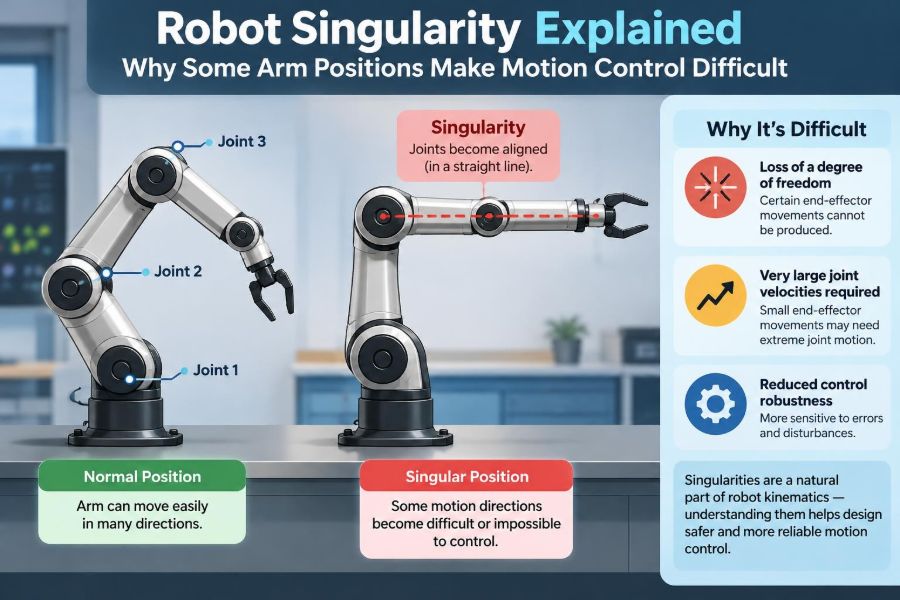

A robot arm can look perfectly capable right up to the moment it slows down, shakes, takes an odd detour, or refuses a move that seems simple. The target may be only a few centimeters away. The motors may be healthy. Yet the controller reports a warning about a singularity.
This is a familiar moment in welding cells, pick-and-place stations, surgical robotics, camera rigs, and student labs. A pose that looks ordinary in the physical workspace can be mathematically awkward for the robot to reach or pass through.
Robot singularities are not mysterious failures or proof that a robot has “lost control.” They are special configurations where the usual relationship between joint motion and tool motion becomes incomplete, ambiguous, or dangerously amplified.
Understanding them helps engineers design safer paths, choose better robot layouts, tune motion limits realistically, and diagnose behavior that would otherwise seem unpredictable.
🧭 What a Robot Singularity Actually Is
A singularity is a robot configuration at which the arm loses one or more independent directions of instantaneous motion. In practical terms, the end effector—the tool, gripper, torch, or camera—cannot move or rotate in every desired way without a problematic joint response.
Near a singularity, a small requested tool motion may demand very large joint velocities. At the singular configuration itself, more than one joint-motion combination may produce the same tool motion, or a desired tool motion may be unavailable.
The key word is configuration. Singularity is usually about the arm’s current geometry, not a permanent defect in the robot.
🗺️ Why Pose Matters More Than Location Alone
Robots do not merely place a tool at an XYZ point. They usually control a full pose: position plus orientation. A welding torch, for example, may need to be at a point while also pointing at a specific angle.
Two poses can share the same Cartesian location but have different wrist orientations. One may be easy to reach; the other may place aligned joints in a singular configuration. This is why a program can work for one tool angle and struggle after a seemingly minor orientation edit.
🔗 The Chain of Joints Behind Every Tool Move
Most industrial arms are serial mechanisms: links connected one after another by rotary or linear joints. Motion at every joint contributes to the tool’s final position and orientation.
In a typical six-axis arm, the first joints broadly position the arm, while the final three wrist joints orient the tool. Their contributions overlap in useful ways, but that overlap can disappear at certain alignments.
The robot controller must continuously convert a desired tool motion into coordinated joint motion. Singularities are where this conversion becomes ill-conditioned or partly undefined.
🔢 Forward and Inverse Kinematics
Forward kinematics answers a straightforward question: if every joint angle is known, where is the tool? The controller calculates the resulting tool pose from the arm’s geometry.
Inverse kinematics reverses the question: given a desired tool pose, what joint angles should the robot use? This problem can have several valid answers, one answer, or no exact answer within joint limits.
Singularities are especially visible in inverse kinematics because the solver may find that a requested Cartesian motion corresponds to infinitely many joint solutions or requires impossible joint rates.
📐 The Jacobian: The Motion Translation Map
Engineers describe the local connection between joint velocities and tool velocity with a matrix called the Jacobian. It is a compact map of how each joint contributes at the current pose.
In simplified form, the relationship is written as v = J(q) q̇, where v is the tool’s linear and angular velocity, q̇ is the vector of joint velocities, and J(q) depends on the current joint configuration.
When the Jacobian loses rank, the robot is singular. When it is close to losing rank, its inverse becomes poorly behaved: modest tool commands can turn into extreme joint-speed demands.
🚪 A Door-Hinge Analogy for Lost Motion
Imagine trying to move the edge of a door in every possible direction while it remains attached to a hinge. The door can sweep through an arc, but it cannot move freely sideways through the wall. The hinge arrangement constrains the available motion.
A robot near singularity has a related limitation, although its geometry is more complex. Certain joints become aligned or redundant for a particular instantaneous motion, so the arm loses a distinct way to create that tool movement.
The robot is not necessarily stuck. It may still reach the next pose by changing its path, changing its orientation, or moving away from the troublesome configuration first.
🦾 The Three Common Singularity Families
Names vary by manufacturer and arm geometry, but six-axis articulated robots commonly encounter three broad categories.
| Type | Typical geometry | Practical symptom |
|---|---|---|
| Wrist singularity | Two wrist axes align | Rapid changes in wrist joint angles |
| Elbow singularity | Arm links become nearly collinear | Weak or ambiguous motion around the extended arm |
| Shoulder singularity | Wrist center lies near a base-axis line | Large base-axis motion for small tool changes |
These categories are useful diagnostic shorthand, not universal labels. The exact singular sets depend on the robot’s joint-axis arrangement and tool definition.
🌀 Wrist Singularity and Aligned Axes
A common spherical wrist has three intersecting rotary axes. When the first and third wrist axes become aligned, rotation about one physical direction can be produced by many combinations of the two outer wrist joints.
The controller loses a clean way to separate those joint contributions. A small commanded change in tool orientation may cause one wrist joint to accelerate sharply while another compensates in the opposite direction.
This is sometimes called wrist flip behavior. It does not mean the controller is random; it is choosing between mathematically equivalent or near-equivalent joint descriptions.
📏 Elbow Singularity at Full Reach
Consider a human arm reaching straight forward with the elbow nearly locked. Small sideways wrist motion may be possible, but some motions become harder to generate cleanly because the upper arm and forearm are nearly in a line.
An articulated robot has a comparable elbow singularity when major links align. The arm may lose sensitivity in a direction, and the elbow configuration can become ambiguous: “elbow up” and “elbow down” branches meet or become difficult to distinguish.
Full extension also tends to reduce useful margin against reach limits, collision zones, and torque constraints, so it is often a poor place for demanding process motion.
🎯 Shoulder Singularity Near the Base Axis
In many robot designs, the first joint rotates the entire arm around a vertical or base-centered axis. If the wrist center lies directly on or very close to that axis, the required base angle becomes poorly defined.
Picture pointing a long arm straight upward over its own base. A tiny sideways change can correspond to a large change in the base rotation angle, even though the tool barely moves in space.
This can produce abrupt base-joint travel, poor path quality, or a controller warning. The exact behavior depends on the robot’s geometry and the inverse-kinematic branch selected.
⚙️ Why Joint Speeds Can Explode
A Cartesian command such as “rotate the tool smoothly at this rate” is expressed at the tool. The controller must distribute that requirement across joints. Near singularity, the geometry gives the controller less mechanical leverage in a needed direction.
To compensate, it may request increasingly fast joint motion. If joint velocity limits are reached, the robot cannot maintain the programmed Cartesian speed or orientation trajectory.
This is why a path can slow down even when the tool seems to be moving only a short distance. The limitation is often not linear travel distance; it is the required joint coordination.
📉 Conditioning: Trouble Before the Exact Singularity
Robots do not need to sit exactly at a singularity before motion becomes difficult. The more relevant operating concept is conditioning, which describes how sensitive the joint solution is to small changes in tool motion.
A poorly conditioned Jacobian indicates that noise, interpolation changes, or tiny pose adjustments can cause disproportionately large changes in joint velocity. Controllers often monitor a singularity metric or issue warnings before the mathematical boundary is reached.
That protective behavior is useful. A warning zone gives programmers room to revise a path before speed limits, tracking errors, or abrupt posture changes affect production.
🧩 Redundancy Does Not Eliminate Singularities
A robot with more degrees of freedom than the task requires is called redundant. A seven-axis arm, for example, may have an extra joint that allows it to alter elbow posture while holding the same tool pose.
Redundancy can provide valuable escape routes around singular configurations. The controller can use the extra freedom to keep joints away from limits or preserve a preferred posture.
But redundancy does not make every pose harmless. It changes the available solution space and often improves maneuverability, while introducing new planning choices and possible singular configurations of its own.
🛤️ Cartesian Paths Can Be Harder Than Joint Paths
In joint-space motion, each joint moves toward a target according to its own trajectory. The tool usually follows a curved path through physical space, but the controller has direct freedom to avoid extreme coordinated rates.
In Cartesian motion, the controller tries to keep the tool on a prescribed line, arc, or orientation path. That constraint can force the arm through a poor configuration.
Neither mode is universally better. A straight Cartesian path may be essential for dispensing, cutting, or insertion, while a joint-space transition may be safer between process points.
🔥 Process Quality Can Reveal a Singularity
Singularity trouble is not always first noticed as an alarm. In a weld, abrupt wrist behavior can change torch orientation or travel consistency. In dispensing, a speed reduction can alter bead geometry if process parameters are not coordinated.
For a vision camera, unstable orientation can shift the field of view. In machining or force-sensitive work, abrupt posture changes may alter stiffness and contact behavior.
These effects should not automatically be blamed on singularity; calibration, payload, compliance, and control tuning also matter. Still, inspecting the robot configuration along the path is a sensible diagnostic step.
🧰 The Tool Center Point Changes the Picture
The tool center point, or TCP, is the point and orientation frame used to program the tool. It may be the tip of a gripper finger, the end of a nozzle, or a point ahead of a camera lens.
Changing a tool can shift the TCP far from the wrist flange. That does not usually alter the robot’s underlying geometric singularities, but it can make their practical effects more severe because a small wrist rotation moves the TCP through a larger arc.
Accurate TCP calibration is therefore essential. A poorly defined TCP can make path behavior look like a singularity issue, or obscure a genuine one.
📦 Payload and Inertia Add Real-World Limits
Singularity is fundamentally a kinematic issue, meaning it concerns geometry and motion relationships. Real robots also face dynamics: motor torque, payload mass, inertia, gravity effects, vibration, and braking limits.
Near a singularity, high joint acceleration demands can combine badly with a heavy or offset payload. The controller may reduce speed, reject the motion, or report a different limit before a singularity warning appears.
Good planning considers both layers. A mathematically reachable path is not automatically a robust production path.
🧪 A Simple Hypothetical Wrist Example
Imagine a six-axis robot holding a sealant nozzle. The nozzle must follow a vertical seam while its tip remains normal to the surface. Midway through the seam, the required orientation aligns two wrist axes.
If the program insists on a continuous orientation change through that point, the controller may need the outer wrist joints to spin rapidly in opposite directions. The nozzle’s visible orientation can remain nearly unchanged while the joints work intensely underneath.
A practical solution might be to rotate the workpiece slightly, choose a different approach orientation, or divide the path so the arm reconfigures away from the seam. Which option is best depends on process tolerances and cell constraints.
🧭 Configuration Branches and Robot Posture
Many tool poses have multiple inverse-kinematic solutions. An arm may reach a point with its elbow high or low, with the wrist flipped or non-flipped, and with different base-axis choices.
These alternatives are often called configuration branches. A branch is not merely a cosmetic posture: it changes joint limits, collision clearance, cable routing, stiffness, and distance from singularities.
Programmers should select and preserve a suitable branch deliberately where their controller allows it. Letting the solver switch branches unexpectedly can create large joint moves between visually similar poses.
🚧 Joint Limits and Singularities Can Team Up
A singularity may be manageable in open space but become troublesome when one or more joints are near their travel limits. The controller then has fewer ways to distribute the required motion.
For example, a wrist near alignment might normally use two joints to share a rotation. If one is close to its limit, the other must absorb more of the motion and may exceed a speed limit.
Evaluate joint-limit margin throughout the path, not just at endpoints. A configuration that reaches both programmed points safely can still pass through a constrained region in between.
🧱 Collision Avoidance Can Remove the Easy Escape
Robot simulations may show several valid postures, but fixtures, guards, cables, dress packs, neighboring robots, and the workpiece eliminate many of them. A singularity workaround that is mathematically elegant may be physically impossible.
This is one reason offline programming must be checked in a realistic cell model and then verified carefully on the actual system. Small differences in tooling, calibration, or cable behavior can matter.
Collision avoidance and singularity avoidance should be planned together rather than treated as separate final checks.
🖥️ What Controllers Commonly Do
Controller behavior differs by manufacturer, software version, motion type, and configuration settings. Many systems monitor proximity to singularity and respond by warning, slowing the motion, limiting orientation interpolation, or stopping when constraints cannot be met.
Some controllers provide configuration data, singularity-avoidance options, or smoothing features. These can be helpful, but they do not repeal geometry. A setting that masks a warning may trade it for a less predictable path or reduced process accuracy.
Always interpret controller diagnostics using the vendor documentation for the specific robot and application. Safety-related changes should be assessed through the cell’s established risk and validation process.
🔍 How to Diagnose a Suspected Singular Path
Start by identifying the exact point where behavior changes. Compare tool pose, joint angles, joint velocities, and commanded versus achieved speed immediately before and after that point.
- Visualize the path and robot posture in simulation, if available.
- Check whether wrist axes or major arm links are approaching alignment.
- Review joint-speed peaks, joint-limit margin, and selected configuration branch.
- Confirm TCP, work-object frames, payload, and calibration data.
- Run at reduced speed only as a diagnostic measure, not as a permanent substitute for a sound path.
Reduced speed may make a move appear acceptable because it lowers velocity demand. It does not remove the underlying poor conditioning.
🛠️ Path Design Strategies That Usually Help
The most reliable remedy is often to alter geometry rather than force the controller through the problem. Even a small orientation, fixture, or intermediate-pose change can move the arm into a much better-conditioned region.
- Use an intermediate waypoint that changes arm posture before the critical process segment.
- Adjust tool orientation within the process’s allowable angular tolerance.
- Reposition or reorient the workpiece, fixture, or robot base where cell design permits.
- Select a different inverse-kinematic branch early, before the arm reaches the warning zone.
- Use joint-space travel for non-process transitions when a strict Cartesian path is unnecessary.
The best choice preserves the true process requirement rather than treating every programmed orientation as equally nonnegotiable.
📐 Design for Dexterity, Not Just Reach
During cell layout, it is tempting to ask only whether the robot can reach every required point. A better question is whether it can reach those points with useful posture, speed margin, collision clearance, and orientation freedom.
Place the highest-precision or highest-speed work where the robot has comfortable elbow bend and a non-extreme wrist posture. Reserve marginal areas for simpler transitions when possible.
For new systems, evaluate representative process paths—not only isolated reachability points. A robot that reaches all corners of a part may still be a poor fit for the required continuous path.
🧮 Numerical Methods Need Care Near Singularities
Some controllers and software use numerical inverse kinematics, especially for redundant robots or custom mechanisms. Near singularities, directly inverting the Jacobian can become unstable because the matrix is singular or nearly singular.
A common engineering approach is a damped least-squares method, which softens the inversion and avoids unbounded joint-velocity commands. It can produce graceful behavior near a singularity, but typically accepts some tracking error or altered motion priority.
That trade-off must be explicit. Numerical regularization is a control tool, not a physical escape from lost dexterity.
⚖️ Singularity Avoidance Has Trade-Offs
Avoiding singularity can increase path length, cycle time, energy use, or fixture complexity. In a tightly constrained cell, it may also push the robot closer to a collision zone or another joint limit.
Conversely, passing near a singularity may be acceptable for a slow, noncritical transition with adequate margin and predictable controller behavior. The decision should reflect task precision, speed, payload, stopping requirements, and process consequences.
The goal is not to maximize distance from every singularity at all costs. It is to avoid configurations whose sensitivity exceeds what the application can safely and reliably tolerate.
⚠️ Common Programming Mistakes
One common mistake is teaching points manually until the robot reaches each location, then assuming the path between them will be equally good. Continuous motion exposes the configurations in between.
Another is treating a singularity warning as a nuisance to suppress. Warnings may be conservative, but they often identify real sensitivity that will surface when speed, payload, or production variation changes.
A third mistake is changing a wrist angle without checking the entire upstream posture. Tool orientation and arm configuration are coupled; a local-looking edit can move the robot toward a different singular family.
👷 Safe Commissioning Practices
Singularity-related behavior can involve unexpected joint speeds or posture changes. During commissioning, use appropriate reduced-speed procedures, maintain clear space, and follow the robot manufacturer’s operating and safeguarding requirements.
Validate the complete motion at production-relevant payloads and speeds only after low-risk checks confirm the intended path and configuration. Watch external cables and hoses as well as the robot links; dress-pack interference can become a hazard before a formal collision is detected.
No general article can replace the robot manual, cell-specific risk assessment, or qualified engineering judgment. These are especially necessary when modifying safety settings, motion limits, or automated recovery behavior.
🎓 What Students Should Practice First
A useful lab exercise is to command the same tool pose using different elbow and wrist configurations. Observe how joint angles, joint limits, and collision clearance differ even though the tool appears unchanged.
Next, move a tool through a simple orientation sweep while watching joint velocities. Then repeat from a different arm posture. This makes the Jacobian’s geometric role much easier to grasp than equations alone.
Students should learn both viewpoints: Cartesian space describes the task, while joint space reveals what the mechanism must physically do to accomplish it.
🏭 What Working Engineers Should Document
For production cells, record the preferred configuration branch, known warning zones, approved recovery positions, TCP definition, payload data, and any orientation tolerances used to avoid poor geometry.
That documentation prevents a later edit from quietly undoing a carefully chosen solution. It also makes troubleshooting faster when a new part revision, fixture shift, or tool change affects motion.
Include singularity checks in change control for paths that are speed-sensitive, quality-critical, or near joint limits. A simulation screenshot and joint-trace review can communicate risks clearly across programming, process, and maintenance teams.
🧠 The Core Principle: Geometry Sets the Rules
Robot singularities are a direct consequence of mechanism geometry. At certain poses, the arm cannot independently produce every small tool motion in the usual way, or it needs disproportionate joint motion to do so.
They are not inherently catastrophic, and they are not solved by simply demanding more from the motors. Good robot engineering recognizes them early, selects a suitable posture and path, and accounts for real constraints such as payload, collisions, process quality, and joint limits.
The lasting lesson is simple: program the tool path, but always evaluate the joint-level motion required to create it.
A robot moves reliably when its task is designed around the arm’s geometry, not merely around the points the tool must touch. 🦾📐⚙️