
A car body moves down an assembly line, and a robotic arm appears to know exactly where to weld. In another factory, a palletizing robot stacks boxes in a stable pattern while a vision-guided arm sorts parts arriving in random orientations. The machines look independent, but none of them learned the job by simply watching the floor.
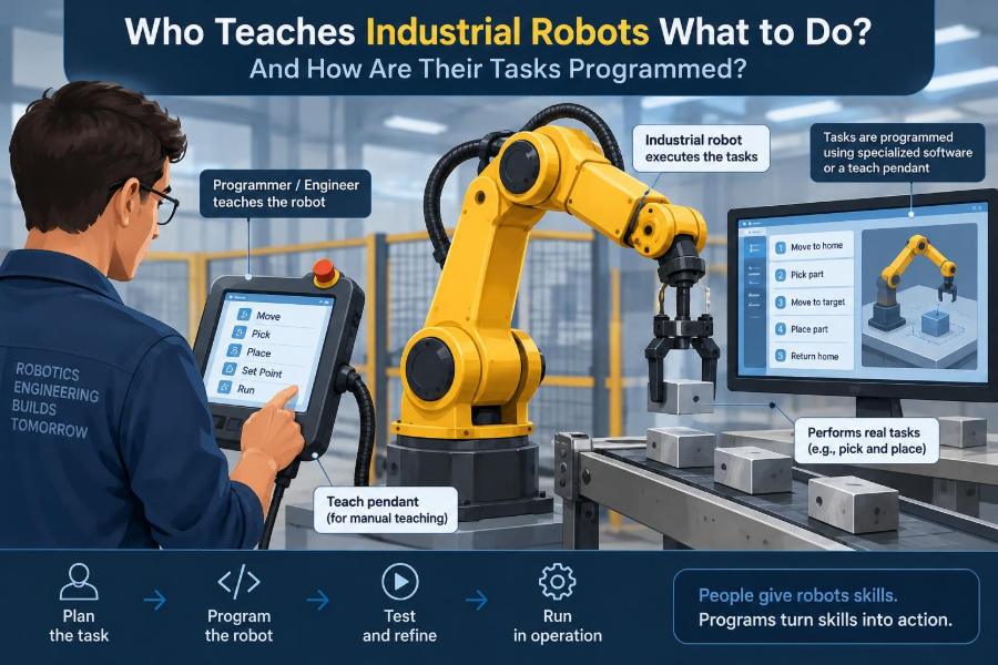
Every reliable robot motion began as a human decision: which part matters, where it should go, how quickly it may move, what happens when something is missing, and when the machine must stop. That work may be done by a robot programmer, controls engineer, systems integrator, technician, or an operations team working together.
Understanding who programs robots matters because an industrial robot is not just a mechanical arm. It is one piece of a larger automated cell that includes tooling, sensors, conveyors, safety equipment, and software. A correct arm motion can still produce a failed system if it arrives at the wrong time or ignores a safety condition.
The practical question is not only “How do you move a robot?” It is “How do people translate a manufacturing task into motions and decisions that remain safe, accurate, and repeatable through thousands of production cycles?”
🏭 Industrial Robots Execute Instructions, Not Intentions
An industrial robot has no inherent understanding of a weld, a carton, or a quality requirement. It follows programmed instructions that define positions, motion types, speeds, inputs, outputs, and decision logic.
People often describe a robot as “doing a job.” Technically, the controller is executing a sequence or program. The useful human skill is turning the job’s real-world goal into precise conditions the controller can evaluate.
👥 The Team Behind a Robot Cell
In a small facility, one experienced person may handle setup, programming, and troubleshooting. Larger projects usually divide the work among specialists because mechanical design, electrical controls, safety, and production knowledge all affect the final program.
- Manufacturing or process engineers define the task: required throughput, tolerances, materials, and quality checks.
- Robot programmers create robot paths, tool behavior, and recovery routines.
- Controls engineers connect the robot to PLCs, sensors, conveyors, and plant systems.
- Mechanical engineers and tool designers develop grippers, fixtures, and end-of-arm tooling.
- Technicians and operators provide essential knowledge about setup, wear, changeovers, and actual production problems.
Titles vary by company. What matters is that the people responsible collectively understand both the process and the automated equipment.
🧩 Start With the Process, Not the Programming Screen
Before anyone teaches points, the team must define the process. For a pick-and-place cell, that includes where parts arrive, how they are identified, where they are placed, and what should happen to rejected or missing parts.
This stage exposes assumptions that can otherwise become expensive faults. For example, “pick the part from the conveyor” is incomplete if parts can arrive upside down, overlap, drift in position, or fail to appear.
📋 Turning a Job Into Requirements
A good automation requirement describes observable outcomes rather than vague wishes. “Handle boxes quickly” becomes a target cycle time, allowable box dimensions, payload range, stack pattern, and criteria for a successful pick.
Requirements also include abnormal cases: empty feeder, low air pressure, full pallet, open gate, jammed conveyor, or failed sensor. These conditions are central to programming because real production is full of transitions and exceptions.
🦾 Choosing the Robot and Its Tool
Programming depends on physical capability. A robot must have adequate reach, payload, speed, accuracy, and suitable protection for its environment. A food-processing robot, for instance, may need a washdown-capable design that differs from a robot used inside a dry machine enclosure.
The end effector—the tool mounted at the robot wrist—often determines whether a task works at all. Grippers may use fingers, vacuum cups, magnets, adhesive methods, or specialized process tools such as welding torches and dispensing nozzles.
A robot cannot compensate indefinitely for a poorly designed gripper. If a flexible bag sags, a vacuum cup leaks, or a workpiece shifts in a fixture, the program must confront a mechanical problem rather than hide it with increasingly complex code.
🧭 Coordinate Frames Give Motion Meaning
Robot positions are interpreted within coordinate frames, which are defined reference systems. The robot’s base frame is attached near its base; a tool frame describes the active point on the gripper or tool; a work frame describes the part, fixture, table, or other work area.
Imagine saying “move 50 millimeters to the left.” Left relative to what? Without a frame, the instruction is ambiguous. With a work frame, the same programmed path can be related to a fixture rather than the building.
🎯 Tool Center Point Calibration
The tool center point, often called TCP, is the point the controller treats as the operational tip of a tool. It might be the center of a suction cup, the tip of a welding wire, or the midpoint between gripper fingers.
If the TCP is inaccurate, a robot can appear to reach taught points yet miss the actual target. Calibration tells the controller where that effective point sits relative to the wrist and how the tool is oriented.
📍 Teaching Positions With a Pendant
A common method is teach-pendant programming. A trained user holds a handheld controller, jogs the robot at reduced speed, and records important positions such as approach points, pick points, and safe home positions.
Teaching is more than saving coordinates. The programmer chooses a safe approach direction, checks that the tool clears obstacles, and decides whether the robot should use a straight path or a joint-based move between locations.
🕹️ Jogging Is Deliberate, Not Casual
Jogging moves a robot manually under controlled conditions. It may be done in joint coordinates, where individual axes move, or in Cartesian coordinates, where the tool moves along directions such as X, Y, and Z in a selected frame.
Manual movement can be hazardous around large machines or tight fixtures. Facilities use defined safety procedures, appropriate operating modes, reduced-speed functions where applicable, and trained personnel. Exact requirements depend on the robot, cell design, and applicable local rules and standards.
↔️ Joint Moves and Linear Moves
Most robot languages support several motion types. A joint move allows axes to take an efficient coordinated route toward a destination, but the tool tip may follow a curved path. A linear move commands the TCP to travel in a straight line between points.
Linear motion is useful when entering a tight fixture, inserting a part, applying adhesive, or welding along a seam. Joint motion is often suitable for open-space travel where avoiding singular paths and shortening cycle time matter more than a straight tool trajectory.
| Motion choice | Typical use | Programming concern |
|---|---|---|
| Joint move | Travel through open space | Tool path between endpoints is not necessarily straight. |
| Linear move | Insertion, dispensing, seam work | Requires clear straight-line access and sensible orientation control. |
| Arc or circular move | Curved paths and some process operations | Intermediate geometry and calibration affect path quality. |
🧠 Robot Programs Combine Motion and Logic
A useful program does not merely list coordinates. It combines movement with conditions: turn on a vacuum output, wait for grip confirmation, notify a conveyor, check that a fixture is clamped, or branch to a fault routine.
In simplified pseudocode, a pick operation might read like this:
move to approach_point
move linearly to pick_point
turn vacuum on
wait for part_detected
move to safe_height
Real code adds timeouts, error handling, signals, and validation. The key idea is that physical motion and machine decisions are programmed together.
🔌 PLCs Coordinate the Whole Cell
A programmable logic controller, or PLC, often acts as the coordinator for equipment around the robot. It may control conveyors, valves, guards, stack lights, and process sequencing while exchanging status signals with the robot controller.
For example, a PLC can tell a robot that a fixture is ready. The robot then performs its operation and returns a completion signal. Clear signal definitions prevent both devices from acting on assumptions.
🤝 Handshakes Prevent Confused Equipment
A handshake is a planned exchange of signals confirming that one device is ready for the next step. “Request,” “ready,” “busy,” “complete,” and “fault” are common concepts, though the exact implementation varies.
Consider a robot loading a machine. It should not enter merely because the machine was ready a moment ago. A robust sequence verifies current conditions, commands the action, waits for acknowledgment, and handles a timeout if acknowledgment never arrives.
👁️ Sensors Tell the Program What Actually Happened
Sensors give the robot cell information about the physical world: a part has arrived, a gripper is closed, a pallet is present, pressure is sufficient, or an area is occupied. This feedback makes an automated sequence more resilient than blind timing alone.
Still, a sensor is not magic. It can be misaligned, obscured, damaged, or unable to distinguish a good part from a similar bad one. Programming should account for plausible sensor failures rather than treating every signal as unquestionable truth.
📷 Vision Systems Handle Variation
Machine vision is used when a fixed location is not enough. A camera can locate randomly oriented parts, inspect visible features, read codes, or estimate where an object lies within a calibrated workspace.
A vision system generally provides data to a robot or PLC; it does not eliminate the need for careful programming. Lighting, part presentation, camera calibration, and the range of acceptable variation strongly influence whether the solution is dependable.
🧮 Offline Programming Builds Cells Before Installation
Offline programming uses a digital model of the robot cell to create and test paths before the physical equipment is available. It is especially useful for complex layouts, large robots, or projects where installation time is limited.
Simulation can reveal reach problems, obvious collisions, and approximate cycle-time issues. But a virtual model may not include every cable bend, fixture tolerance, material behavior, or sensor delay found on the real floor.
🔄 Digital Models Need Real-World Commissioning
Commissioning is the stage where a programmed cell is brought to life, tested, and adjusted in its actual environment. Teams verify frames, tool data, I/O wiring, safety interfaces, timing, and recovery behavior.
A simulated path that clears a fixture by a few millimeters may require revision when the installed fixture is slightly different. This is not necessarily a simulation failure; it reflects the unavoidable gap between nominal design data and physical equipment.
⏱️ Cycle Time Is More Than Robot Speed
Cycle time is the time required to complete a repeatable production sequence. Increasing robot speed may reduce travel time, but it can also increase vibration, worsen part handling, shorten stopping margins, or expose bottlenecks elsewhere.
Often the better improvement is to reduce unnecessary motion, place parts more consistently, shorten a gripper’s response delay, or overlap independent work. The fastest arm does not help if it waits for a slow conveyor or a fixture to unclamp.
📐 Accuracy, Repeatability, and Process Tolerance
Repeatability describes how consistently a robot returns to a commanded position. Accuracy describes how closely that position matches its intended location in the world. The distinction matters whenever the robot must interact with external fixtures or changing parts.
Many industrial tasks succeed because fixtures constrain the part and the robot repeats well. If absolute placement relative to a distant machine or irregular incoming part is required, calibration, sensing, or vision may be needed.
🧱 Fixtures Make Automation Easier
A fixture holds a workpiece in a known and repeatable location. It may seem less exciting than a robot, but it often carries much of the solution by controlling part orientation and resisting process forces.
For a hypothetical welding cell, a precise fixture can allow a simpler taught path. If the same part is loosely placed each cycle, the programmer may need seam tracking, vision, or a more tolerant process—each adding cost and complexity.
🛡️ Safety Is Designed Into the Task
Robot safety is not a final checklist item. It affects layout, access, operating modes, guarding, interlocks, emergency stops, restart behavior, and the program itself. Risk assessment should be performed by competent people for the specific cell and its intended use.
A safe program includes predictable fault states. When an error occurs, it should avoid creating a new hazard by suddenly restarting motion, dropping a load, or allowing a person to enter an area before stored energy and movement risks are controlled.
🚨 Recovery Routines Separate Reliable Cells From Fragile Ones
Production interruptions happen: a part slips, an operator reloads material, power is restored, or a sensor remains blocked. A recovery routine guides the system from a known abnormal state back to a safe, understandable state.
Good recovery logic identifies what is known and what is not. If the controller cannot confirm whether a part remains in the gripper, it should not simply continue as if the pick succeeded. Human verification may be the safest next step.
🧪 Testing Includes the Bad Cases
Testing should verify normal production, but it must also challenge expected faults. Teams may deliberately simulate a missing part, failed grip confirmation, blocked sensor, delayed machine response, or interrupted cycle in a controlled manner.
The question is not whether the program can stop. It is whether it stops in a safe state, gives a useful diagnostic, and can be restored without confusing the operator or damaging equipment.
🗂️ Documentation Preserves the Cell’s Knowledge
Robot cells outlive individual projects and employees. Clear documentation records tool data, frame definitions, I/O maps, program versions, maintenance points, backup procedures, and the intended sequence of operation.
Without it, a simple sensor replacement can become risky detective work. With it, technicians can distinguish a mechanical issue, an electrical issue, and a software issue more quickly.
🧰 Version Control Prevents Mystery Changes
Robot programs and PLC logic should be backed up and managed as controlled engineering assets. A documented version gives the team a known baseline when troubleshooting or comparing production changes.
Unrecorded edits create a familiar problem: the cell worked yesterday, but no one knows what changed. Even small changes to speeds, frames, timers, or I/O logic can have meaningful consequences.
🔧 Maintenance Changes Can Affect Programming
Replacing a gripper, moving a fixture, servicing a wrist, or changing conveyor hardware can alter the assumptions built into a program. The work may require recalibration, retesting, and an updated backup even if the code itself appears unchanged.
Operators and maintenance teams are often first to notice drift, unusual sound, longer pickup times, or recurring minor faults. Treating these observations as process data can prevent a larger failure later.
⚠️ Common Programming Mistakes
Many robot problems are not caused by exotic software bugs. They come from incomplete assumptions, rushed teaching, and insufficient testing of the real process.
- Teaching a point without a safe approach and retreat path.
- Using fixed delays where a sensor confirmation is needed.
- Ignoring what happens after a timeout or loss of communication.
- Changing a tool without checking TCP and payload data.
- Optimizing speed before the process is stable and safe.
- Leaving unclear alarms that do not tell operators what to inspect.
The remedy is usually systematic: define states, confirm assumptions, test transitions, and document the result.
🎓 Skills for People Entering Robot Programming
Programming skill is valuable, but it is only one layer. New practitioners benefit from learning coordinate systems, basic mechanics, electrical I/O, pneumatic or vacuum behavior, sensors, safety concepts, and structured troubleshooting.
Practice reading a sequence as a system: What starts the action? What confirms success? What could prevent the next step? What is the safe response when the answer is uncertain? This mindset transfers across robot brands and industries.
🧑🏭 Operators Are Part of the Automation System
Operators may load material, acknowledge faults, inspect quality, change tools, and report recurring issues. Their interface should make normal work clear and fault recovery deliberate rather than forcing them to guess at hidden program states.
Training should explain boundaries: what an operator may reset, what requires maintenance support, and what condition demands escalation. A well-designed cell respects operator knowledge while avoiding unsafe informal workarounds.
🌐 Collaborative Robots Change Access, Not Fundamentals
Collaborative robots, often called cobots, are designed for certain forms of closer human-robot interaction. They can simplify some deployments, particularly lower-payload tasks and flexible workstations, but they do not remove the need for task-specific risk assessment.
A cobot carrying a sharp tool, moving a heavy payload, or operating near pinch points may still require safeguarding measures. Programming fundamentals—frames, tooling, sensing, sequencing, and recovery—remain the same.
📈 What “Teaching” Really Means
Industrial robots are taught through a combination of physical demonstration, coordinate data, written logic, sensor feedback, and carefully defined limits. The exact mix depends on the task: a repeatable fixture may rely heavily on taught points, while variable parts may require vision and adaptive logic.
The strongest automation is rarely the most elaborate. It is the system whose mechanical design, software, controls, and human procedures agree about what should happen in both routine and abnormal conditions.
🏁 The Core Principle: Program the Process, Not Just the Arm
The person who “teaches” a robot is really part of a team translating production knowledge into a controlled system. They define motion, but also timing, confirmation, safe failure, recovery, and the communication between machines.
A robot path is only one chapter of the program. Reliable industrial automation comes from teaching the entire cell how to recognize conditions, act deliberately, and respond safely when reality does not match the plan.
Industrial robots become useful not when an arm can move, but when people give the whole process clear, testable, and safe instructions. That is the craft behind the smooth, repeatable motion seen on a factory floor. 🦾🏭🔧