
A robot can make perfect parts all morning, then begin missing a fixture by just enough to create a problem. The first sign may be a press-fit that suddenly feels tight, a vision correction that grows larger, or an operator who has started “nudging” a taught point to keep production moving.
That situation raises two questions that sound similar but demand different tests: Can the robot return to the same location repeatedly? And is that location still where the program says it should be?
The distinction matters in welding, dispensing, machine tending, inspection, assembly, and laboratory automation. A robot may be extremely consistent while being consistently offset from the required point. Conversely, it may be correctly calibrated on average but scatter too much from cycle to cycle.
Measuring the right behavior, under controlled conditions, turns vague concerns about “robot drift” into evidence that can guide maintenance, process correction, or a deeper mechanical investigation.
🎯 Repeatability and Accuracy Are Different Properties
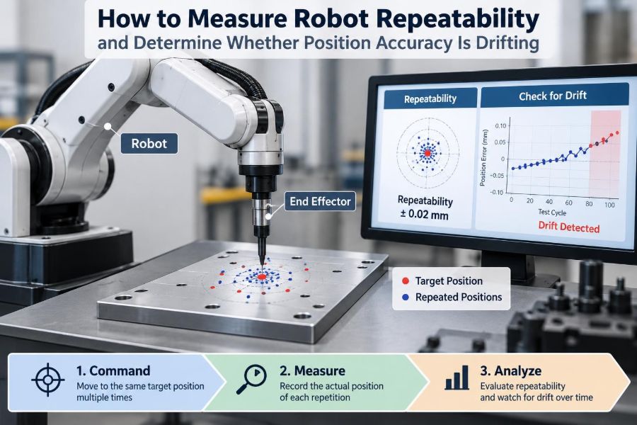
Repeatability is the robot’s ability to return to the same pose when it repeats the same commanded move under the same conditions. A pose includes position and orientation, not merely the XYZ location of the tool center point.
Position accuracy is the difference between the commanded or intended pose and the pose the robot actually reaches in a defined reference frame. A robot can have strong repeatability but poor absolute accuracy if every return is consistently shifted.
Think of darts: a tight cluster away from the bullseye is repeatable but inaccurate. Darts spread around the bullseye may average accurately, but they are not repeatable enough for a tight process.
📍 Define the Pose That Actually Matters
Before measuring anything, state what “correct” means for the application. A palletizing task may tolerate a few millimeters at pickup but require reliable angular alignment at a drop-off. A sealant bead may tolerate small position error yet fail if tool angle changes.
Record the required point, coordinate frame, tool orientation, allowable error, payload, speed, approach direction, and process state. A measurement without this context can look precise while answering the wrong production question.
For most end-effector tasks, evaluate the tool center point (TCP): the programmed point on the tool used by the controller to calculate motion.
🧭 Separate Robot Error From Cell Error
A part can be misplaced even when the robot is behaving normally. Fixtures wear, pallets vary, locating pins collect debris, cameras shift, and tool changers introduce small seating differences. These are cell-level errors, not automatically robot-position errors.
Start by choosing the reference frame deliberately. Testing against a stable artifact attached to the robot base asks about robot behavior. Testing against production tooling asks whether the complete cell still achieves its task. Both tests are valuable, but their results should not be mixed.
📏 Choose a Measurement Method That Fits the Tolerance
The measurement system must be substantially more capable than the error you need to detect. A steel rule cannot diagnose a sub-millimeter trend, and a high-resolution laser system may be unnecessary for a coarse pallet placement check.
| Method | Best use | Key limitation |
|---|---|---|
| Dial indicator or contact probe | Focused point-to-point checks | Usually measures limited directions |
| Precision fixture or gauge pin | Routine production verification | Fixture condition becomes part of the result |
| Vision system | Planar location and process-facing checks | Calibration, lighting, and lens effects matter |
| Laser tracker or metrology arm | 3D accuracy and larger workspaces | Requires setup discipline and environmental control |
Consult the instrument’s stated performance, calibration status, setup requirements, and uncertainty guidance. Do not report more decimal places than the method can defend.
🧪 Build a Test That Can Be Repeated Later
A useful baseline test is simple enough that another technician can perform it months later. Freeze the program revision, identify the robot, tool, controller software, measurement device, and datum artifact.
Write down the commanded pose and all conditions that can affect it: robot mounting, payload, external axes, active tool data, user frame, speed override, braking state, and warm-up condition. Photos of the setup can be as useful as numerical records.
A test procedure is not bureaucracy. It prevents an apparent drift trend caused by a quietly changed tool definition or different test geometry.
🔧 Verify the Tool Center Point First
A wrong TCP makes every measured end-effector position look wrong. It can be caused by a bent tool, a loose adapter, an incomplete tool calibration, a replacement gripper with slightly different geometry, or a tool changer that does not seat consistently.
Recheck TCP calibration using the controller’s appropriate method and a stable reference point. If the TCP result changes significantly between careful recalibrations, investigate tool rigidity, mounting faces, cable forces, and the calibration procedure before blaming the robot arm.
Also verify tool orientation. In a long tool, a small angular error can create a much larger positional error at the working tip.
🗺️ Confirm Base and User Frames
Robot programs are often taught in a user frame tied to a fixture, machine, or conveyor. If that frame is wrong, all points can move together while the robot’s internal joints remain fully repeatable.
Check frame definitions after fixture work, robot relocation, controller restoration, or program transfer. A common trap is compensating a shifted fixture by editing many taught points instead of correcting the underlying frame.
Use independent physical datums wherever possible. A frame should be verified against known geometry, not merely accepted because the displayed values resemble an old backup.
🌡️ Control Warm-Up and Temperature Effects
Motors, gearboxes, brakes, structures, and nearby process equipment change temperature during operation. Thermal expansion is real, and temperature-dependent friction or backlash behavior can alter the pose reached under load.
Measure both a cold condition and a representative production-warm condition when the process is sensitive. The goal is not necessarily to eliminate all temperature-related change; it is to understand whether the observed movement is predictable, acceptable, and within the process window.
A comparison between a just-powered robot and a robot after sustained production should never be labeled “drift” without noting this difference.
🏋️ Match the Production Payload and Process Forces
Repeatability measured with an empty gripper may not represent a loaded robot. Payload mass, center of gravity, cable dress, hose tension, and external process forces can all deflect the arm or change servo effort.
Test with the actual tool and a representative payload. For welding, dispensing, or deburring, include conditions that create meaningful reaction forces if they occur at the measured pose.
Payload data entered into the controller must also be realistic. Incorrect mass or center-of-gravity values can affect motion behavior and, depending on the system, protection or performance functions.
🔁 Use a Consistent Approach Direction
Backlash, gear compliance, joint friction, and gravity can make the final position depend on how the robot approaches it. A target reached from the positive side of a joint may not match the same target reached after reversing direction.
For a routine repeatability test, use one defined approach path and stop condition. Then run a second, deliberate direction-reversal test if you want to expose hysteresis or backlash-related behavior.
This distinction is especially relevant in applications where a robot approaches a fixture from varied paths rather than following one tightly controlled cycle.
🔢 Collect Enough Repetitions to See the Pattern
One successful return proves very little. Repeat the move enough times to reveal whether results form a tight cloud, a directional spread, occasional outliers, or a steady movement over time.
At each cycle, record the measured X, Y, and Z result, and orientation when relevant. Include a time or cycle number. If the data are gathered automatically, preserve the raw file rather than keeping only an average.
More repetitions are useful when the process tolerance is tight or the behavior appears intermittent. The practical question is whether the sample exposes the variation that production actually experiences.
📊 Read the Scatter, Not Just the Average
An average can hide the problem. Ten measurements may average exactly at target while individual returns alternate on opposite sides of the allowable band.
Review the range, distribution, and direction of error. Plotting each coordinate against cycle count is often more revealing than a single pass/fail number. A compact cluster with an offset points toward accuracy or calibration. A broad cluster points toward repeatability, compliance, or measurement variation.
If your organization uses a formal capability method, apply it only when the sampling plan and underlying assumptions fit the data. Do not let a familiar statistic replace inspection of the actual measurements.
📐 Measure Position and Orientation Together
A robot can place its TCP near the expected point while presenting the tool at the wrong angle. That may be harmless for a vacuum cup but unacceptable for a welding torch, probe, or precision insertion tool.
Where orientation matters, use a metrology method capable of observing it, or measure a feature that amplifies angular error. For example, checking the far end of a rigid reference bar can reveal orientation changes that are difficult to see at its base.
Keep rotational and translational results distinct. Combining them into one unexplained score can obscure the failure mode.
🧷 Run a Practical Repeatability Check With a Fixture
A well-designed check fixture can support daily or weekly verification. For example, a robot-mounted conical pin may enter a precision bushing, touch indicator tips in multiple directions, or align with a camera target.
The fixture must be rigid, protected from accidental impact, and periodically inspected. A worn bushing or shifted bracket can create a false robot alarm.
- Bring the robot to the defined approach point.
- Move to the test pose using the recorded path and speed.
- Capture the measurement without manually pushing the tool.
- Retract and repeat for the planned number of cycles.
- Compare the spread and center with the established baseline.
Interlocks and safe speeds are essential. A measurement fixture should never encourage personnel to enter a hazardous robot workspace during automatic motion.
🔭 Use Independent Metrology for Absolute Accuracy
When the question is absolute accuracy across a workspace, an external coordinate measurement system is usually needed. A laser tracker, portable arm, calibrated vision arrangement, or other suitable system can compare actual poses with commanded coordinates in a common reference frame.
Measure multiple locations, not only one convenient point. Accuracy can vary with reach, joint configuration, payload, and direction of travel. Points near a kinematic singularity or at the edge of reach may behave differently from central workspace points.
Follow the metrology system’s setup and uncertainty procedures. External measurement is powerful, but poor line of sight, unstable targets, or weak registration can invalidate an otherwise sophisticated test.
📈 Establish a Baseline Before Calling It Drift
Drift is a change over time relative to a comparable baseline. A single offset is evidence of an offset, not proof that the robot is drifting.
Create a baseline after commissioning, calibration, major maintenance, or a verified good-production condition. Save the central result, normal variation, test setup, and acceptance criteria. Then repeat the same test at defined intervals or after relevant events.
A trend chart is especially useful because it distinguishes a one-time step change from gradual movement. Those patterns often suggest different causes.
📉 Recognize Common Drift Patterns
A gradual shift in one direction may suggest thermal behavior, slow fixture movement, wear, or changing cable forces. A sudden step change after a collision, tool replacement, or maintenance event points toward a discrete mechanical or configuration change.
Periodic variation can follow production temperature cycles, tool-change cycles, or a particular joint configuration. Random isolated points may indicate intermittent contact, measurement noise, loose hardware, or an unresolved process disturbance.
Pattern recognition is not diagnosis by itself. It narrows the next inspection so the team avoids recalibrating blindly.
🧱 Inspect Mechanical Sources of Changing Position
Mechanical causes deserve attention when repeatability worsens, direction dependence grows, or a position shift is linked to load. Look for loose base bolts, damaged tooling, worn locating features, gearbox or joint issues, excessive compliance, and evidence of collision.
Also inspect cable bundles, dress packs, hoses, and process lines. They can apply changing forces to the wrist, particularly near the limits of motion. A cable that catches intermittently can mimic an intermittent robot fault.
Use manufacturer-approved maintenance procedures. Do not attempt to adjust joints, brakes, or reducers without the required training and safety controls.
⚙️ Check Configuration and Control Causes
Not all shifts are mechanical. Restored backups, modified calibration data, incorrect encoder mastering, altered user frames, changed tool data, software changes, and external-axis synchronization issues can change where a robot goes.
Compare current configuration against a known-good controlled backup. Review alarms and event history around the first observed failure, especially after power events, collisions, or service work.
Encoder mastering and calibration are safety- and model-specific procedures. If there is doubt, follow the robot manufacturer’s documented process or involve qualified service personnel.
👁️ Audit the Measurement System Itself
A surprising number of “drift” investigations end at the gauge. A camera may have moved, illumination may have changed, a probe may be bent, an indicator may have been zeroed differently, or a measurement target may be dirty.
Perform a simple gauge check against a stable reference before relying on the results. If possible, use a second independent method to confirm a meaningful trend.
Measurement uncertainty does not mean testing is useless. It means small changes near the system’s resolution should be treated cautiously rather than interpreted as definite machine movement.
🏭 Compare Robot Behavior With Process Output
Robot pose data and product quality should be examined together. A measured position shift that has no process effect may be within a robust process window. A tiny shift may be critical if it affects an insertion chamfer, a seal edge, or a weld joint.
Useful process-facing evidence includes inspection results, force signatures, vision corrections, bead placement, pick failure location, or machine interface alarms. These clues help prioritize work without confusing correlation with proof of cause.
The best acceptance limits are derived from functional requirements, then allocated sensibly among robot, fixture, part variation, and measurement error.
⚖️ Set Limits With a Tolerance Budget
Do not use the robot’s catalog repeatability value as the entire cell acceptance criterion. That value is measured under specific conditions and does not automatically include the tool, fixture, part, process force, or measurement system.
Build a tolerance budget that identifies the contributors to total error. Some contributors are fixed offsets, some vary from cycle to cycle, and some depend on temperature or load. This makes it clearer whether a tighter robot test can meaningfully improve the finished process.
When uncertainty is high, use conservative decision rules and seek better measurement rather than declaring a marginal result good or bad with false confidence.
🚦 Define Escalation Rules Before Production Is Affected
A monitoring plan needs actions, not only numbers. Define what happens when results cross an alert threshold, when they exceed a stop threshold, or when a sudden shift follows an incident.
- Alert: repeat the test, verify the gauge, and inspect recent changes.
- Action: check TCP, frames, tooling, fixture condition, and configuration.
- Escalation: involve maintenance, controls, metrology, or the robot supplier when evidence points beyond routine correction.
- Containment: inspect affected product when position performance may have compromised quality or safety.
The exact limits are application-specific. A medical device assembly and a carton palletizing cell should not inherit the same response plan.
🛑 Treat Collisions as Measurement Events
After a crash, hard stop, dropped payload, or unexpected contact, do not assume that clearing an alarm returns the system to its prior condition. Inspect the tool, fixture, mounting, cabling, and affected robot path.
Run a documented verification move or repeatability check before resuming sensitive work. Even when the robot has no obvious fault, the event may have shifted a fixture, damaged a tool, or changed a component that affects the process.
Collision recovery should prioritize personnel safety and manufacturer guidance over rapid restart.
🗂️ Keep Records That Support Diagnosis
A good record includes raw readings, calculated results, date, operator, robot program revision, TCP and frame identifiers, payload, environmental notes, and any relevant maintenance or collision history.
Store baseline plots and setup photographs with the procedure. If an offset appears six months later, this history can reveal whether it began after a tooling change, a new product, a controller update, or seasonal temperature conditions.
Trend data becomes valuable when it is consistent. A loosely repeated test produces a loose conclusion.
🧠 Avoid the Most Common Diagnostic Mistakes
The first mistake is adjusting taught points immediately. That may mask a shifted fixture, bad frame, or loose tool and makes future troubleshooting harder. Correct the cause before applying a program compensation.
Other frequent mistakes include testing without production payload, comparing cold and warm data as though they were identical conditions, using only one point, and trusting a gauge that has not been checked.
Finally, avoid treating repeatability and accuracy as interchangeable. Each requires a different interpretation and may require a different fix.
🔄 Use Compensation Carefully
Software compensation can be appropriate when an error is stable, understood, and managed through change control. Examples include a verified fixture-frame update or an approved calibration correction after a controlled mechanical change.
Compensation is risky when used to conceal random variation, continuing movement, backlash, or a damaged component. It may restore one point while worsening another, especially across a large workspace.
Document every correction and rerun the verification test afterward. A compensation should improve measured performance, not merely make a screen coordinate look plausible.
🧭 A Practical Investigation Sequence
When a robot appears to be missing position, move from simple, reversible checks toward deeper intervention. This protects uptime while keeping the evidence clear.
- Confirm the product symptom and identify the affected pose.
- Verify the measurement device and reference artifact.
- Check tool condition, TCP, payload, and user frame.
- Repeat a controlled return-to-point test with the production approach and load.
- Compare results with baseline data and recent events.
- Inspect fixtures, mounting, cabling, and collision evidence.
- Review calibration, mastering, configuration, and external-axis status.
- Escalate for qualified service or external metrology when needed.
This order is not universal, but it prevents costly disassembly before common setup causes have been ruled out.
✅ The Core Principle: Measure the Right Error Over Time
Reliable robot verification begins with a clear question. If you need to know whether the robot returns consistently, measure repeatability under controlled, production-relevant conditions. If you need to know whether it reaches the intended physical location, measure accuracy against an independent, stable reference.
To determine drift, repeat the same well-documented test over time and examine the direction, magnitude, and pattern of change. Treat the robot, tool, fixture, payload, environment, and gauge as a system rather than assuming the arm is the only possible source.
That approach creates actionable evidence: whether to recalibrate a TCP, repair a fixture, investigate a mechanical issue, improve a measurement method, or simply confirm that the process remains capable.
A robot’s position is trustworthy not because it was correct once, but because a controlled measurement system continues to show where its variation and offsets come from. 🦾📏📈