
A delivery robot leaves a well-lit lobby, rolls across a reflective glass entrance, and reaches a damp sidewalk. Its camera briefly loses contrast in the glare. Its wheel encoders report motion, but one wheel slips. Its lidar sees a nearby hedge clearly, but not the transparent glass door it has just passed.
None of those sensors is useless. Each is doing what it was designed to do. The problem is that a mobile robot must make navigation decisions in environments where every sensing method has blind spots.
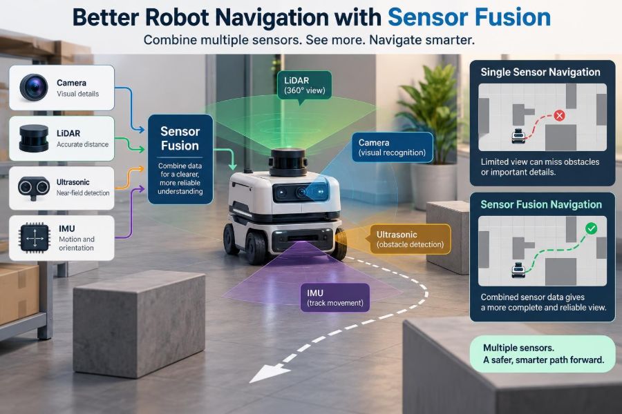
This is why reliable robots do not usually ask one sensor to tell the whole story. They combine complementary measurements, estimate what they cannot observe directly, and keep operating when one input becomes less trustworthy.
Sensor fusion is the discipline of turning several imperfect, differently timed observations into a better estimate of a robot’s position, motion, and surroundings. It is central to robots that must move safely beyond a tightly controlled demonstration space.
🧭 Why a Single Sensor Rarely Tells the Full Story
A navigation sensor measures only a particular aspect of reality. A camera measures light, an inertial measurement unit measures acceleration and rotation, and a lidar estimates range from reflected laser pulses. None directly provides a complete, error-free answer to “Where am I, and can I move there?”
Single-sensor navigation can work in constrained settings. A line-following robot on a clean floor may need little more than optical reflectance sensors. But as speed, autonomy, environmental variation, or safety requirements increase, the assumptions behind that simple solution break down.
📍 What Robot Navigation Actually Requires
Navigation is not one calculation. A capable mobile robot typically needs localization, mapping or map matching, perception of obstacles, route planning, and low-level motion control.
Localization estimates the robot’s pose: its position and orientation. Perception identifies useful features and hazards. Planning chooses a feasible path, while control continually corrects the motors to follow it. Sensor fusion supports each layer, but the most common starting point is pose estimation.
🧩 The Core Idea Behind Sensor Fusion
Sensor fusion combines measurements according to what they reveal and how uncertain they are. It is not simply averaging every number available. A good system gives more influence to a sensor that is currently reliable and less influence to one whose conditions are poor.
Think of walking through fog while using a phone map. Your internal sense of direction helps between landmarks, but a recognizable building can correct a growing directional error. Fusion gives the robot an equivalent way to predict motion and then correct that prediction with outside evidence.
📏 Wheel Encoders: Useful Motion Estimates with Drift
Wheel encoders count wheel rotation. With wheel diameter and axle geometry, the robot can estimate how far it has traveled and how much it has turned. This method is called odometry.
Odometry is inexpensive, responsive, and available even in darkness. Its weakness is accumulated error. Wheel slip, uneven floors, cable drag, worn tires, and small calibration errors all cause the estimated pose to drift away from the real one over time.
🌀 IMUs: Fast Motion Sensing, Imperfect Long-Term Position
An IMU usually contains accelerometers and gyroscopes. Gyroscopes provide useful short-term estimates of angular velocity, which helps a robot stabilize its heading during rapid turns. Accelerometers sense specific force and can contribute to motion estimates.
However, integrating acceleration into velocity and position magnifies small biases. Gravity must also be modeled accurately. An IMU is therefore excellent for fast prediction, but it generally needs external corrections to maintain long-term localization.
📷 Cameras: Rich Context, Conditional Geometry
Cameras can identify lane markings, doors, shelves, fiducial markers, and visually distinctive places. Stereo cameras or depth cameras can also provide geometric cues. They deliver semantic information that range sensors may not: a camera can help distinguish a person from a wall.
Visual performance depends on illumination, exposure, texture, motion blur, weather, and lens cleanliness. A plain white corridor provides few stable features, while changing shadows may create misleading ones. Vision is powerful, but it should not be treated as universally dependable.
🔦 Lidar: Strong Geometry with Its Own Gaps
Lidar produces distance measurements across a scan pattern, often making walls, furniture, and other solid structures easy to localize against. Two-dimensional lidar is common for indoor floor robots; three-dimensional lidar adds vertical structure at greater cost and data volume.
Yet lidar returns depend on surface properties and geometry. Glass, highly reflective materials, rain, dust, narrow objects, and low-mounted scan planes can cause missing or confusing returns. A lidar can see a wall precisely while failing to observe an obstacle outside its scanning plane.
📡 Radar and Ultrasonic Sensors Fill Specific Blind Spots
Radar can remain useful in conditions that degrade optical sensors, and it can measure relative velocity well in many configurations. Its angular resolution may be coarser than lidar or cameras, so it is often most valuable as a complementary sensor rather than the only perception source.
Ultrasonic sensors are inexpensive and helpful at short range, especially for detecting nearby surfaces. Their wide beam patterns and sensitivity to material, angle, and environmental conditions limit precision. Used thoughtfully, they can add a valuable last layer of proximity awareness.
🛰️ GNSS Is Helpful Outdoors, Not a Universal Position Source
Global Navigation Satellite System receivers can provide a global reference for outdoor robots. They are useful for field machines, delivery platforms, and robots traveling across large sites where a local map alone is insufficient.
Buildings, trees, multipath reflections, tunnels, and indoor operation can degrade availability and accuracy. Treat GNSS as one measurement source with quality indicators, not as unquestionable ground truth. Local odometry, inertial sensing, and map-based corrections remain necessary.
🗺️ Maps Turn Measurements into Location Evidence
A map lets the robot compare a current observation with known structure. For example, a lidar scan can align with a stored occupancy map, or a camera can recognize a mapped visual landmark. This process supplies corrections that prevent dead-reckoning drift from growing unchecked.
Maps also become stale. A warehouse may rearrange racks, a construction site changes weekly, and a hallway can be blocked by carts. Navigation software must distinguish persistent structure from temporary objects rather than forcing every observation to fit an outdated map.
⏱️ Time Synchronization Is a Navigation Requirement
Fusion fails quietly when measurements have incorrect timestamps. A camera frame captured before a turn should not be fused as though it was captured after the turn. At higher speeds, even modest timing offsets can create visible position and orientation errors.
Use a common clock where possible, preserve hardware timestamps, and account for sensor transport and processing latency. The fusion system should estimate the state at the measurement time, not merely at the time software happens to receive the message.
📐 Coordinate Frames Must Be Explicit
Every measurement has a coordinate frame: camera frame, lidar frame, IMU frame, base frame, wheel frame, map frame, or global frame. Transformations define how these frames relate. If the lidar is mounted slightly forward and to the left of the robot center, that offset matters.
Frame mistakes can resemble sensor noise but are often systematic: maps appear to slide during turns, obstacle locations shift with heading, or a robot consistently tracks beside its intended path. Naming frames clearly and maintaining one documented transform tree prevents many costly debugging sessions.
🔧 Calibration Connects the Sensors to Reality
Calibration estimates quantities such as wheel radius, wheelbase, camera intrinsics, IMU bias, and the fixed pose between sensors. Intrinsic calibration describes a sensor’s own measurement behavior. Extrinsic calibration describes where it sits relative to other sensors.
Calibration is not permanent. Vibration, impacts, temperature changes, tire replacement, and remounting a bracket can change a previously valid setup. Recheck calibration after mechanical changes and validate it using observable behavior, not only a configuration file.
📊 Uncertainty Is the Language of Good Fusion
A measurement should carry more than a value; it should carry an estimate of confidence. In mathematical terms, systems often represent uncertainty with a variance or covariance. Larger uncertainty means the estimator should be more cautious about following that measurement.
Confidence should be context-sensitive when practical. A vision system may report lower confidence in low light. Encoder uncertainty may rise when slip is likely. Static values can be a workable beginning, but adaptive uncertainty often makes real robots less brittle.
⚖️ Prediction and Correction Form the Basic Loop
Most navigation estimators repeat two stages. First, they predict the next pose from recent motion, often using encoders and IMU data. Second, they correct that prediction when lidar matching, visual landmarks, GNSS, or another external observation becomes available.
This structure is useful because fast sensors keep the estimate responsive, while slower or intermittent sensors stop it from drifting. If a correction is temporarily unavailable, the robot can still move cautiously on its predicted state rather than becoming instantly blind.
🧮 The Kalman Filter Family in Practical Terms
A Kalman filter estimates a state and its uncertainty while blending a motion model with noisy measurements. It works especially well when the relevant dynamics and measurement relationships are approximately linear and noise can be represented reasonably.
Robots commonly use extensions when reality is nonlinear. An Extended Kalman Filter linearizes the system around the current estimate. An Unscented Kalman Filter propagates carefully selected sample points through nonlinear functions. Neither is automatically superior; model quality, tuning, computation, and failure behavior matter.
🕸️ Particle Filters Handle Ambiguous Locations
A particle filter represents many possible robot poses as weighted hypotheses. After a robot moves, the hypotheses move. After it senses the environment, hypotheses that better explain the observation receive more weight.
This approach is particularly useful when the robot could plausibly be in several locations, such as identical-looking corridors. It can be computationally heavier than a compact Gaussian estimate, but its ability to represent multiple possibilities is a major practical advantage.
🧠 Factor Graphs Support Larger Estimation Problems
Factor graphs model poses, landmarks, sensor biases, and observations as connected variables and constraints. They are widely useful in simultaneous localization and mapping, often called SLAM, where the robot estimates its trajectory while building or refining a map.
A graph-based approach can revisit older constraints when new evidence arrives, helping reduce accumulated error and close loops. The trade-off is more complex implementation and careful management of computation, memory, and delayed updates.
🏭 A Practical Indoor Fusion Stack
Consider a warehouse robot moving among racks. A sensible baseline might use wheel encoders and an IMU for high-rate local motion, 2D lidar for localization against fixed rack geometry, and short-range safety sensors near the chassis.
A camera may add barcode, pallet, or human-aware perception, but it does not need to carry the entire localization burden. This division of labor is usually more robust than choosing one “best” sensor and forcing it to solve unrelated tasks.
🌦️ Outdoor Robots Need Environmental Diversity
An outdoor inspection robot may combine GNSS, IMU, encoders, lidar, cameras, and a terrain-aware motion model. GNSS gives broad geographic context, while local sensing handles nearby obstacles and maintains control when satellite reception weakens.
Rain, dust, direct sun, mud, and vegetation affect sensors differently. A robust design asks not only what performs well on a clear test day, but what continues to provide useful information when the usual sensor becomes degraded.
🚦 Localization and Obstacle Detection Are Different Jobs
A robot can know its pose accurately and still collide with a new obstacle. Conversely, it can detect a person reliably while being uncertain about its own global location. These functions exchange information, but they should be evaluated separately.
For example, a static map can localize the robot using walls, while a local costmap tracks carts and people as dynamic hazards. Keeping persistent map features separate from transient obstacles prevents the robot from “learning” temporary clutter as permanent geometry.
🛑 Safety Requires More Than a Better Pose Estimate
Fusion improves navigation, but it does not replace safety engineering. A navigation estimate can be plausible and still be wrong due to shared environmental effects, calibration errors, or unmodeled failures.
Safety-oriented behavior should include conservative stopping margins, speed limits tied to perception confidence, independent emergency-stop pathways where appropriate, and explicit fallback modes. A robot that notices uncertainty and slows down is often safer than one that continues confidently with weak observations.
🔍 Detect Sensor Failures Instead of Averaging Them In
Not every bad measurement looks obviously impossible. A camera can produce believable but incorrect feature matches; a lidar can align with repeating structure; a GNSS receiver can report a position that appears smooth but is biased by reflections.
Use innovation or residual checks: compare the new measurement with what the current state predicts. Large or statistically unlikely disagreement can trigger rejection, reduced weighting, or a diagnostic event. Crucially, thresholds require testing; overly aggressive rejection can discard the very correction the robot needs.
🔁 Redundancy Works Best When Failures Differ
Adding two sensors of the same type is not always meaningful redundancy. Two cameras mounted side by side may both struggle in darkness. Two wheel encoders may both be affected by the same slippery surface.
More resilient redundancy comes from different sensing principles: inertial sensing plus wheel motion, laser ranging plus vision, or global positioning plus local map matching. Their errors are less likely to occur in exactly the same way at the same time.
🧪 Test the Awkward Cases, Not Just the Happy Path
Navigation stacks often look excellent on recorded data from familiar routes. Validation should include turns, stops, reversals, low texture, bright backlighting, wheel slip, narrow passages, changing payloads, partial map changes, and temporary sensor dropout.
Log raw measurements, timestamps, transforms, estimator outputs, and confidence values. A replayable dataset makes it possible to compare tuning changes fairly and investigate failures without guessing what the robot saw.
🎛️ Tune Models Before Blaming the Algorithm
Switching from one estimator to another will not fix inaccurate wheel geometry, an unaccounted sensor delay, or a map that does not match the building. Many “fusion problems” originate in the data pipeline and physical integration rather than in advanced mathematics.
Start with a simple, observable state: position, heading, and perhaps velocity. Add bias states or extra sensors only when their measurements can constrain them. A smaller model that is calibrated and monitored often outperforms an elaborate model with poorly understood parameters.
💻 Manage Compute, Bandwidth, and Latency
High-resolution cameras and dense point clouds can overwhelm an embedded computer or network. If perception arrives too late, its accuracy may not help control decisions. Downsampling, region-of-interest processing, efficient data structures, and separate real-time pathways can be more useful than indiscriminately adding sensor resolution.
Measure end-to-end latency, not just algorithm runtime. Include capture, transfer, queueing, inference, synchronization, estimation, planning, and actuator response. The robot experiences the complete delay chain.
📈 Define Metrics That Reveal Navigation Quality
Useful metrics depend on the mission. Pose error against a trusted reference can help during development, but operational measures matter too: route completion, recoveries from localization loss, unnecessary stops, clearance from obstacles, and behavior during sensor degradation.
Examine distributions and failure cases, not only averages. A low average error can hide rare but serious jumps in the estimated pose. For a robot that shares space with people, predictable degradation can be more valuable than impressive performance under ideal conditions.
🪜 A Sensible Implementation Sequence
- Define the operating environment, speed, safety constraints, and failure conditions the robot must handle.
- Build and validate encoder-plus-IMU odometry with correct frames, timestamps, and basic calibration.
- Add one external correction source, such as lidar map matching, visual markers, or GNSS, and verify its behavior independently.
- Fuse sources with explicit uncertainty and logging before adding more complexity.
- Introduce health checks, fallback behavior, and scenario-based testing for dropouts and disagreement.
This staged approach makes it easier to identify which addition improved the system and which introduced a hidden assumption.
🚫 Common Fusion Mistakes to Avoid
- Assuming more sensors always means more accuracy: poorly calibrated inputs can make an estimate worse.
- Ignoring correlated errors: two inputs influenced by the same failure should not be treated as fully independent evidence.
- Using fixed trust values everywhere: sensor reliability changes with lighting, terrain, speed, and weather.
- Fusing unverified transforms: a small mounting error can corrupt every downstream estimate.
- Evaluating only localization: the robot must still plan and stop safely when estimates become uncertain.
🔮 Choosing the Right Fusion Architecture
There is no universal sensor suite or estimator. A slow indoor cleaner may benefit most from encoders, IMU, and 2D lidar. A drone requires strong inertial integration and different constraints. An agricultural platform must account for GNSS conditions, terrain, vegetation, and wheel slip.
Choose based on observability: can the available measurements actually reveal the state you need? Then consider failure modes, compute budget, maintenance, calibration effort, and acceptable behavior when confidence falls. The best architecture is the one that meets the mission with understandable limitations.
🤝 The Core Principle: Complementary Evidence Beats False Certainty
Sensor fusion improves robot navigation because different sensors compensate for different weaknesses. Encoders and IMUs provide rapid motion continuity. Lidar, cameras, maps, and GNSS can correct drift or add environmental context. Health checks and uncertainty modeling prevent a questionable input from dominating the estimate.
The goal is not to create a robot that never encounters uncertainty. The goal is to build one that recognizes uncertainty, combines evidence intelligently, and responds safely when the world refuses to match its assumptions.
Reliable navigation comes from managing imperfect information, not pretending one sensor can make the robot perfectly certain. Design the sensing stack around complementary strengths, careful timing, calibration, uncertainty, and safe fallback behavior. 🦾🧭🔧