
A robot cell that once met its target can slowly become a source of small, expensive frustrations. Parts land slightly off-center in a fixture. A dispensing bead wanders near an edge. A camera-guided pick succeeds most of the time, but not reliably enough to run unattended.
The immediate reaction is often, “This robot is not accurate enough.” That diagnosis may be right—but it does not automatically mean the answer is a new robot. Accuracy is a system outcome, shaped by mechanics, tooling, calibration, sensing, programming, process variation, and measurement.
Replacing the arm can be costly and disruptive, and it may leave the underlying cause untouched. A new manipulator mounted on a shifting base, using a worn gripper, or guided by an unstable vision setup can reproduce the same quality problem with better specifications.
A more productive question is: where does the position error enter the system, and which changes remove the largest part of it? The answer often leads to targeted upgrades that are faster, safer, and more durable than a full replacement.
🎯 Start by Separating Accuracy, Repeatability, and Resolution
These terms are related, but they diagnose different problems. Accuracy is how close the robot reaches a commanded or real-world target. Repeatability is how consistently it returns to the same point. Resolution is the smallest commanded movement the controller can represent or detect.
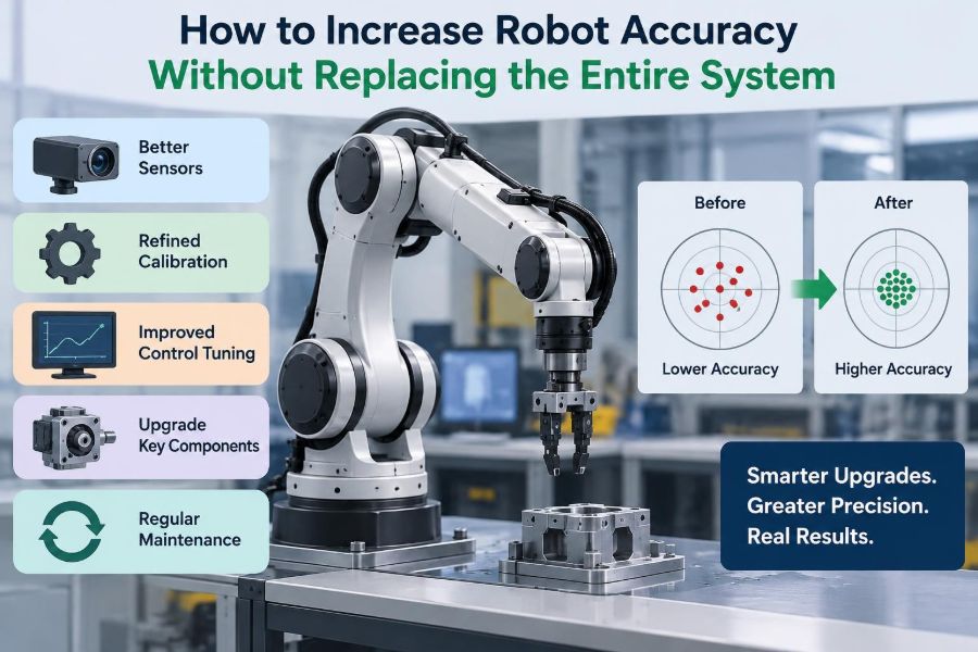
A robot can be highly repeatable but inaccurate. Imagine an archer who places every arrow in a tight cluster 50 mm left of the bullseye: the pattern is consistent, but it is not correct. This is good news, because a stable offset is often correctable through calibration, frames, or compensation.
Poor repeatability is harder. It suggests changing error from cycle to cycle, often caused by backlash, compliance, thermal movement, inconsistent parts, or sensing noise. First identify which kind of behavior you actually have.
📏 Define the Requirement in Process Coordinates
“More accurate” is not a usable engineering requirement. State what feature matters, relative to what datum, over what operating conditions. A welding application may care about seam tracking relative to a part edge, while a machine-tending task may care about seating a part within a chuck.
Specify the allowable positional and angular error at the process point: the point where the tool contacts, picks, dispenses, scans, or fastens. Also define the required confidence, cycle time, payload, and part mix.
Without this step, teams may improve an arm’s flange position while ignoring tool-tip angle, or tune a static test while the actual task fails under payload and motion. The process—not the catalog specification—sets the real target.
🧭 Map the Entire Accuracy Chain
A robot does not work alone. Position information and physical motion pass through a chain: base, arm, joints, flange, end effector, workpiece, fixture, sensors, coordinate frames, and program logic. Every element can add an error.
Draw that chain for one representative task. For a vision-guided placement station, it may be: camera measures part, software transforms camera coordinates into robot coordinates, robot moves a gripper, gripper holds part, fixture defines placement, and a final sensor verifies the result.
This map prevents a common blind spot: treating the robot controller as the only source of error. Often the arm is merely executing an incorrect target supplied by another part of the system.
🔍 Measure Before Adjusting Anything
Do not tune based solely on an operator’s impression or one failed cycle. Collect samples across the actual workspace, production speeds, payloads, and orientations. Record both average offset and spread.
Useful measurements may include robot tool-center-point position, angular error, camera-reported coordinates, fixture location, gripper jaw position, and final part position. The best instrument depends on the tolerance: a dial indicator may reveal a loose fixture, while a metrology system may be needed for a tight spatial calibration.
Measure the measurement system too. If a gauge, camera, or manual inspection method contributes substantial variation, it can hide whether a change improved the cell. A noisy ruler cannot validate a very small correction.
📊 Read the Pattern, Not Just the Maximum Error
Error patterns point to likely causes. A constant shift in one direction often indicates a frame, TCP, or datum problem. Error that changes with robot posture may indicate kinematic calibration, joint compliance, cable forces, or mounting movement.
Error that grows with payload suggests deflection. Error that appears after warm-up suggests thermal effects. Random scatter may come from inconsistent gripping, variable parts, loose hardware, communication timing, or sensor instability.
| Observed pattern | Likely area to investigate | Typical response |
|---|---|---|
| Similar offset at many points | TCP, user frame, fixture datum | Recalibrate and verify frames |
| Position-dependent deviation | Robot geometry, base rigidity, reach | Map error; consider compensation or task relocation |
| Load-dependent shift | Tool, arm, mounting, gripping | Reduce moment, stiffen, retune payload |
| Cycle-to-cycle scatter | Backlash, part variation, sensing | Find and reduce the changing source |
One point can mislead. A spatial pattern across several poses is far more informative than a single reported deviation.
🧱 Inspect the Robot Base and Cell Structure
The robot’s coordinate system assumes that its base is stable. If the pedestal, floor anchors, riser, machine frame, or overhead support flexes, the arm can be perfectly repeatable relative to a moving foundation.
Inspect anchor hardware, cracks, corrosion, loose shims, collision damage, and unsupported extensions. Check whether a nearby press, conveyor, door, or other machine introduces vibration at the moment accuracy matters.
Long risers deserve particular attention. They improve reach, but they act like levers: a small angular movement at the base becomes a larger displacement at the tool. Reinforcing a support can produce a larger improvement than changing robot software.
🔩 Reduce End-Effector Deflection
The end effector is often the least rigid part of a robot cell. A long plate, sensor bracket, vacuum cup array, tool changer, or offset spindle can bend or twist under acceleration, process force, or payload changes.
Focus on the distance from the flange to the process point. Increasing that distance amplifies angular errors and deflection. A lighter, shorter, better-braced tool may improve practical accuracy even if the robot itself is unchanged.
Check fasteners, locating features, dowel pins, tool-changer repeatability, and contact surfaces. A well-designed interface locates the tool consistently; bolts alone are not always intended to establish precise position after repeated removal.
⚖️ Verify Payload, Center of Gravity, and Inertia Data
Robot controllers use payload mass, center of gravity, and inertia estimates to control motion. Incorrect values can lead to overshoot, uneven settling, excessive vibration, or conservative behavior that undermines cycle time.
Enter values for the complete moving assembly: gripper, adapters, hoses carried by the wrist, fasteners, sensors, and the heaviest expected part. The center of gravity matters as much as mass because a distant load creates a larger moment.
Use the manufacturer’s approved procedure where available. Do not exceed ratings simply because the robot appears to handle the load in a slow demonstration; dynamic motion and wrist orientation can change the mechanical demand substantially.
🧰 Eliminate Backlash and Wear at the Source
Backlash is lost motion created by clearance between mechanical elements. It can show up when an axis approaches the same point from opposite directions, producing two different final positions.
Inspect gearboxes, bearings, transmissions, brakes, couplings, belts, gripper mechanisms, and tool changers according to the equipment documentation. Unusual noise, heat, vibration, oil condition, repeatability drift, or a history of collisions can justify a deeper service assessment.
Do not mask a growing mechanical problem solely with software offsets. Compensation may keep production running temporarily, but wear that progresses will eventually exceed the correction and may create a safety or quality issue.
🪢 Manage Cables, Hoses, and External Forces
Dress packs and pneumatic hoses can exert surprisingly strong, position-dependent forces on a wrist. A cable bundle that twists, drags across a guard, or catches near one pose can pull the arm away from its nominal path.
Observe the robot slowly through the full working envelope, then at production speed. Look for tension, snagging, changing bend radius, hose contact, and unsupported cable weight. Also consider process forces from drilling, sanding, insertion, welding wire, or sealant contact.
Better routing, proper strain relief, a balanced dress pack, or a compliant process strategy may reduce error. The goal is not merely neat cables; it is consistent external loading throughout the task.
📌 Re-establish a Trustworthy Tool Center Point
The tool center point, or TCP, is the point the controller treats as the active tip of the tool. A wrong TCP makes every programmed target wrong, especially when the wrist changes orientation.
Recalculate the TCP after changing a gripper, replacing a consumable, moving a tool in a holder, servicing a tool changer, or recovering from a collision. Use a method appropriate to the controller and verify it by approaching a fixed reference from several orientations.
If the TCP agrees in one orientation but misses in others, suspect either the TCP calibration, a flexible tool, or robot geometry. Do not accept a calibration just because the controller reports that the routine completed.
🗺️ Calibrate User Frames and Work Object Frames
A user frame, base frame, or work object frame tells the robot where the workpiece is located. When a fixture moves or is rebuilt, old frame data can produce a uniform-looking offset across an otherwise healthy robot path.
Choose datum features that are rigid, accessible, and functionally related to the process. A temporary edge on a loosely mounted plate is a poor reference for a precision operation. Three or more carefully chosen points generally provide a more meaningful frame than a rushed single-point adjustment.
Document the reference features and the calibration method. Future technicians should be able to distinguish an intentional process offset from a frame established on the wrong datum.
🧮 Use Robot Calibration When Geometric Error Matters
Industrial robots are commonly excellent at returning to a taught point, but their absolute position over a large envelope can differ from an ideal geometric model. Link dimensions, joint zero positions, assembly tolerances, and installation conditions all contribute.
Robot calibration uses measured positions to refine the relationship between commanded and actual pose. Depending on the robot and application, this may involve manufacturer procedures, external measurement equipment, or an approved calibration package.
This approach is most useful when tasks rely on offline programming, multiple stations share a coordinate scheme, or the robot must locate features without teaching every point. It requires disciplined measurement; poor reference data simply creates a more sophisticated error.
💻 Apply Error Compensation Carefully
When errors are stable and well characterized, software compensation can be effective. A controller may support offsets, correction tables, path adjustments, or external guidance that modifies targets based on measured deviations.
Compensation is strongest when the cause is stable, the operating envelope is defined, and validation covers all relevant poses. For example, a consistent fixture shift after a planned tooling change may be corrected safely after verification.
It is weak against loose hardware, random part movement, or rapidly changing wear. Treat compensation as a controlled engineering change, with versioned parameters and a clear explanation of what physical behavior it represents.
👁️ Add Vision When the Part Moves or Varies
Vision is useful when a robot cannot assume each part arrives in the same location or orientation. A camera can locate a feature, estimate an angle, inspect an edge, or select a grasp point before motion begins.
It does not automatically create accuracy. The system still needs camera calibration, a stable camera mount, adequate lighting, suitable optics, reliable part detection, and a correct transformation from camera coordinates to robot coordinates.
Use vision to address real variation, not as a decorative layer over a weak fixture. A part that rotates unpredictably in a bin may benefit from vision; a part that should be constrained by simple hard stops may be better served by improving those stops.
💡 Stabilize Lighting and Camera Geometry
Many apparent robot misses are actually measurement misses. Shadows, reflections, changing ambient light, dirty lenses, vibration, and a poorly selected camera angle can move a reported feature location.
Design lighting for the feature being measured. Backlighting can make an outer profile easy to locate, while controlled directional lighting may reveal a raised edge or mark. Shield the scene from changing room light when the tolerance demands it.
Keep the camera and its bracket rigid relative to the frame used for calibration. If a camera sees the world from a slightly different pose after a bump or maintenance event, its previous robot transformation may no longer be valid.
📡 Use Force, Torque, or Compliance for Contact Tasks
Rigid position control is not always the path to better outcomes. For insertion, polishing, deburring, surface following, or uncertain contact, force/torque sensing and compliant tooling can accommodate small geometric differences.
Passive compliance lets the tool move slightly under contact forces. Active force control adjusts robot motion using sensor feedback. Both can reduce jamming and protect parts when contact geometry varies, but both need careful limits and validation.
Compliance should not be mistaken for a cure for gross misalignment. It has a finite travel range, can affect process quality, and may conceal fixture deterioration until the variation becomes too large.
🧲 Improve the Fixture Before Chasing Microns in Software
A robot can only place a part accurately relative to the part location it is given. If the fixture allows a workpiece to float, tilt, deform, or settle differently each cycle, software cannot infer a single correct target without additional sensing.
Use functional datums, positive stops, appropriate clamping force, and features that resist the process loads. In a hypothetical assembly station, improving a locating pin and clamp sequence may remove more placement variation than refining a robot path.
Also consider loading ergonomics. If an operator can place a part in several plausible positions, the fixture is communicating ambiguity to the entire automation system.
🧩 Design Gripping for Repeatable Part Location
A gripper must do more than hold a part securely. It must hold it in a known pose. Soft fingers, uneven vacuum cups, sliding contact surfaces, part burrs, and variable closing force can shift the workpiece between pickup and placement.
Where appropriate, use locating surfaces, nests, mechanical references, or jaw geometry that drives the part into a repeatable position. Confirm whether the part is seated before leaving the pickup point, particularly with flexible, oily, or irregular components.
Gripping force involves a trade-off. Too little can allow slip; too much can deform a thin part or produce variable seating. Test with production material conditions rather than ideal samples only.
🚦 Tune Motion Profiles for Settling, Not Just Speed
A fast robot can arrive at a target while the tool or payload is still oscillating. If the process begins immediately, the apparent accuracy at that instant may be worse than the final static position.
Review acceleration, deceleration, blending, path smoothing, wrist motion, and approach direction near the critical point. Sometimes reducing acceleration only in the last segment provides a stable process without sacrificing the entire cycle time.
Use dwell only when it addresses a measured settling problem. An unexplained pause may hide a mechanical weakness and adds time indefinitely. A better profile or a stiffer tool can be the cleaner solution.
🌡️ Account for Thermal Drift and Warm-Up
Motors, gearboxes, tooling, cameras, and surrounding machinery change temperature during operation. Thermal expansion and changing mechanical behavior can create a repeatable difference between a cold startup and a warmed production cell.
Trend accuracy against operating time and temperature where practical. If a drift pattern is real, options include a controlled warm-up routine, calibration at normal operating condition, environmental control, or compensation validated over the expected temperature range.
Do not assume every drift is thermal. Similar timing patterns can come from a loosening component, accumulating debris, or changing air pressure. Correlate observations before selecting a remedy.
🧼 Control Dirt, Debris, and Process Buildup
Weld spatter, adhesive residue, machining chips, dust, oil, and worn consumables change physical contact points. A few layers of buildup on a locating pin, vacuum cup, nozzle, or inspection window can matter more than a small robot calibration adjustment.
Make cleaning and inspection part of the process plan, not an informal response after failures. Define what surface must be clean, how it is checked, and what condition triggers replacement or maintenance.
In vision and dispensing applications especially, inspect the process point itself. The robot may be accurately following a path while a blocked nozzle or obscured lens produces an inaccurate result.
🔄 Standardize Recovery After Collisions and Maintenance
Collisions, tool changes, encoder battery events, fixture replacement, and mechanical service can all invalidate previously good settings. A cell may restart successfully yet have a changed TCP, frame, camera pose, or mechanical alignment.
Create a recovery checklist that identifies what must be verified after each event. It might include homing or mastering checks, TCP verification, user-frame validation, fixture datum checks, camera calibration confirmation, and a trial part inspection.
Standardization turns tribal knowledge into repeatable practice. It also prevents well-meaning technicians from applying unexplained offsets that later become impossible to trace.
🧪 Validate Changes with a Deliberate Test Plan
One successful demonstration is not enough to establish an accuracy improvement. Test the operating conditions that matter: expected part variation, relevant reaches, orientations, speeds, payloads, and warm versus cold conditions.
Compare before-and-after data using the same measurement method. Look separately at bias, the average directional error, and spread, the cycle-to-cycle variation. A change that removes bias but doubles scatter may not improve the process.
For safety-critical, regulated, or high-consequence tasks, follow the applicable internal procedures, equipment instructions, and validation requirements. Accuracy work can affect motion, forces, guards, and product quality at the same time.
📝 Manage Calibration Data Like Production Data
Frame values, TCP definitions, camera transformations, compensation tables, payload data, and motion settings are engineering assets. Store them with robot program backups, revision history, dates, reason for change, and verification results.
Name frames clearly. A label such as Fixture_A_Datum_Rev2 is more useful than Frame3, especially after personnel changes. Record the physical datum and the tool used to establish it.
Good records make drift visible and rollback possible. They also distinguish a carefully validated adjustment from an accidental parameter change made during troubleshooting.
🛠️ Prioritize Upgrades by Error Removed per Disruption
Not every improvement deserves the same investment. Rank potential actions by the error they address, confidence in the diagnosis, effect on safety and quality, downtime, and ease of verification.
A sensible sequence often begins with inspection, cleaning, tightening, frame and TCP verification, fixture improvement, and payload correction. It can then move toward sensing, calibration, redesigned tooling, or more substantial mechanical work if measurements justify them.
This is not a rule that cheap fixes always come first. A worn gearbox or unsafe mount needs prompt attention. The principle is to spend effort where evidence indicates the dominant source of error.
🚫 Avoid the Most Common Accuracy Fixes That Fail
- Teaching around one bad part: the robot may then miss nominal parts.
- Adding offsets without a cause: undocumented corrections accumulate and conflict.
- Testing only at low speed: dynamic deflection and settling remain unseen.
- Trusting a single sensor reading: a measurement error can become a programmed error.
- Correcting the arm before checking the fixture: the part datum may be the real problem.
- Ignoring safety after a motion change: a revised path, speed, or tool can alter clearance and collision risk.
The common thread is premature action. Fast troubleshooting is valuable, but fast guessing produces fragile systems.
🧠 Know When Replacement Really Is the Right Answer
Targeted improvement has limits. Replacement or major refurbishment may be justified when repeatability has degraded beyond serviceable limits, the robot lacks necessary payload or reach, controller support is obsolete, safety functions cannot meet requirements, or the required process tolerance is fundamentally outside the platform’s capability.
It may also be the better option when an application needs capabilities the existing system cannot gain practically, such as substantially better absolute accuracy over a broad workspace, integrated sensing support, or a different kinematic arrangement.
The decision should follow measurement and lifecycle assessment, not frustration. Keeping an unsuitable robot alive with elaborate workarounds can cost more than a planned modernization.
✅ The Core Principle: Improve the System Around the Error
Robot accuracy is rarely a single number that can be purchased or adjusted in isolation. It is the combined result of stable structure, correct geometry, repeatable tooling and fixturing, reliable sensing, appropriate motion, and measured verification.
Begin with the process requirement, measure the error pattern, and trace it through the complete accuracy chain. Correct stable offsets with calibration when justified; remove variable errors by improving mechanics, part control, sensing, or process conditions.
The most durable upgrade is usually the one that makes the source of variation physically less able to occur—not the one that merely adds another offset to the program.
You can often increase robot accuracy dramatically without replacing the robot by diagnosing the full cell, fixing the dominant error source, and validating every change against the real process. That approach turns accuracy from a frustrating symptom into an engineering problem with practical levers. 🦾📐✅