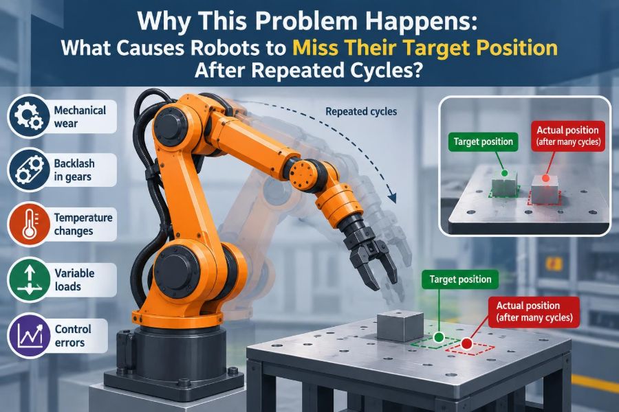

A robot completes the first few pick-and-place cycles perfectly. Then, after an hour of production, a gripper begins landing a few millimetres beside the fixture. Nothing appears dramatically broken, yet the error keeps growing—or returns at the same point in every shift.
This is one of the most frustrating motion problems in robotics because a robot can be repeatable without being accurate, accurate only under certain conditions, or apparently stable until heat, load, timing, or a small mechanical defect exposes a weakness.
For students, the problem connects kinematics, control, sensors, mechanics, and manufacturing. For working professionals, it affects quality, uptime, tool damage, safety margins, and the time spent chasing faults that are often mistaken for “programming issues.”
Repeated-cycle position drift is rarely a single mystery. It is usually a pattern created by a particular error source, a particular operating condition, and a particular way the system measures—or fails to measure—its own position.
🎯 Start by Defining the Failure Clearly
“The robot misses” is not yet a useful diagnosis. Determine whether the robot misses the commanded coordinate, the physical workpiece, or a vision-defined feature. Those are related but different failures.
Record the direction, size, timing, and repeatability of the error. A miss that slowly increases over hundreds of cycles points toward different causes than a fixed offset that appears immediately after every restart.
📍 Accuracy and Repeatability Are Different
Accuracy is how close the robot reaches the intended real-world location. Repeatability is how consistently it returns to the same location. A robot may repeatedly return to the wrong spot with excellent repeatability.
This distinction matters because teaching a new point can hide a calibration error, while a repeatability problem usually demands investigation of mechanics, feedback, motion conditions, or control behavior.
🔁 Why Repeated Cycles Reveal Problems
A single successful move does not prove a system is healthy. Repeated cycling adds heat, exposes backlash during direction reversals, accumulates process debris, and stresses cables and fixtures.
It also makes small timing differences visible. If a robot approaches a part before a conveyor has settled, one isolated cycle may look acceptable while a long sequence reveals a predictable miss.
🧭 Separate Drift from a Fixed Offset
A fixed offset stays roughly constant: every pick is 4 mm left of the intended point. It often suggests an incorrect user frame, tool center point, calibration change, or shifted fixture.
Drift changes with time, cycle count, temperature, direction, or payload. Its changing nature is a valuable clue. Do not treat both patterns with the same corrective action.
🗺️ Coordinate Frames Can Be Wrong
Robot motion is calculated through coordinate frames: the robot base, a user or work frame, a tool frame, and sometimes a camera or conveyor frame. An error in any transformation moves the commanded target away from the physical target.
A bumped fixture plate, a replaced end effector, or a slightly different robot mounting position can invalidate a previously correct frame. The robot may obey its program exactly while the program describes the wrong world.
🛠️ Tool Center Point Errors Move Every Target
The tool center point, or TCP, is the reference location at the end of the robot tool. If the TCP is wrong, orientation changes can create especially noticeable position errors because the controller rotates around an incorrect assumed point.
Consider a long welding torch or inspection probe. A small TCP error near the flange may become a much larger lateral error at the tool tip when the wrist changes angle.
🏗️ Fixture Movement Is Often the Real Problem
When the robot seems to miss, verify that the target has not moved. Fixtures can loosen, wear, flex under clamping force, collect chips, or shift because locating pins are damaged.
Check the part datum—the physical features used to locate the workpiece—not only the robot pose. A robot cannot compensate for a part that arrives inconsistently unless the process includes sensing and correction.
🔩 Backlash Creates Direction-Dependent Error
Backlash is lost motion caused by clearance in gears, reducers, couplings, lead screws, or joints. When motion reverses, the motor can move briefly before the output link fully follows.
A useful test is to approach the same target from opposite directions. If the final physical position differs, backlash or compliance is a strong suspect. The controller’s encoder may report normal motion even while output-side clearance changes the tool pose.
🧱 Mechanical Compliance Lets the Arm Flex
No real robot is perfectly rigid. Links, joints, mounting pedestals, tooling, grippers, and fixtures deflect under load. A heavy payload extended far from the base produces more bending moment than the same payload held close.
Compliance commonly appears as a position error that changes with payload, reach, acceleration, or orientation. It may disappear when the robot is manually jogged slowly, making dynamic testing essential.
⚖️ Payload Data Changes Motion Behavior
Controllers use payload mass, center of gravity, and inertia estimates to plan and regulate motion. Incorrect values can lead to tracking error, vibration, overshoot, or inconsistent settling—particularly during fast starts and stops.
This does not mean every minor payload-data mismatch causes visible errors. But a major tool change without updating the payload model can turn a previously stable path into a repeated-cycle quality problem.
🌡️ Thermal Growth Changes Geometry
Motors, gearboxes, brakes, electronics, tooling, and nearby process equipment warm during operation. Materials expand with temperature, and lubrication behavior can also change as a robot reaches operating temperature.
The resulting motion error may be small, but precision tasks can be sensitive to it. A practical clue is an error that is absent at startup, grows during warm-up, and stabilizes after the system reaches a thermal equilibrium.
🧴 Lubrication and Gearbox Condition Matter
Lubricants reduce friction and support consistent motion. Degraded, incorrect, contaminated, or insufficient lubricant can increase friction, temperature, vibration, and wear. Gearbox wear can also introduce backlash or nonuniform behavior.
Follow the manufacturer’s service procedures rather than treating lubrication as a generic maintenance task. Using an unsuitable lubricant or schedule can create new problems and may affect equipment support requirements.
📡 Encoder Feedback Is Not Always the Tool Position
Encoders measure motor or joint motion, depending on the robot design. They do not necessarily measure every source of deflection between the measured axis and the actual tool tip.
This explains a confusing symptom: the controller says the robot reached its programmed pose, but an external gauge shows the tool is elsewhere. The discrepancy can arise from transmission compliance, backlash, flexing, or an inaccurate kinematic model.
🔌 Cables and Dress Packs Can Pull the Robot
Hoses, welding cables, vacuum lines, and electrical dress packs exert forces on moving axes. If routing is tight, twisted, snagged, or changed after maintenance, the external load can bias the wrist or resist certain orientations.
Look for errors that occur only in a specific region of the workspace or after several turns of an axis. The robot may be fighting the dress pack rather than suffering an internal positioning failure.
⚡ Servo Tuning Can Cause Following Error
A servo system continually compares commanded motion with measured motion. Following error is the difference between the requested and actual axis behavior during motion. Excessive acceleration, poor tuning, friction, or load changes can increase it.
At the end of a move, the robot should settle before performing a precision operation. If the program triggers a weld, insertion, or image capture too soon, residual vibration or settling error can become a process defect.
🏎️ Speed and Acceleration Can Expose the Limit
Fast motion is not inherently inaccurate, but it reduces the margin for flexible structures and poorly matched process timing. High acceleration can excite vibrations in long tools, lightweight fixtures, or compliant robot mounts.
A simple diagnostic comparison is useful: run the same target at a reduced speed and acceleration. If the error changes substantially, investigate dynamic effects rather than immediately reteaching coordinates.
⏱️ Blending Changes the Exact Path
Many robot programs use corner rounding or motion blending to avoid stopping at every waypoint. This improves cycle time, but the robot may pass near—not exactly through—intermediate positions.
If an operation depends on a precise point, use the appropriate fine-position or stop condition for that controller and allow adequate settling. A blended path is not a defect; it is a design choice that must match the task.
👁️ Vision Systems Add Their Own Error Chain
Vision-guided robotics depends on camera calibration, lens behavior, lighting, image processing, hand-eye transformation, and part presentation. A robot can execute a vision correction perfectly while the camera estimates the part pose incorrectly.
Lighting changes, reflective surfaces, dirty lenses, and altered camera mounting can affect results. Validate image coordinates against known physical references before concluding that the robot arm is drifting.
📏 Calibration Can Decay After Physical Changes
Calibration is not permanent in the practical sense that the physical system remains unchanged. Replacing a camera, tool, gearbox, fixture, robot controller, or even a locating component can require revalidation.
Keep a record of what was calibrated, by whom, with which reference artifact, and after what maintenance event. That history turns a vague “it used to work” statement into a tractable engineering timeline.
🚚 Conveyor Tracking Needs Reliable Timing
When a robot tracks a moving conveyor, target position depends on both spatial calibration and time. Encoder scale errors, missed pulses, slip, latency, and variations in part detection can place the robot behind or ahead of the moving part.
Investigate whether the miss changes with conveyor speed. A position error that grows as line speed rises often points toward timing, tracking scale, or detection latency rather than a static robot frame error.
🧠 Program Logic Can Create a Physical Miss
Incorrect variable updates, stale vision results, race conditions between devices, and unexpected branch logic can all command a valid but wrong robot position. The physical motion may look smooth because the robot is doing exactly what the program told it to do.
Log commanded targets, frame selections, process states, and sensor timestamps. Comparing the commanded pose with measured reality helps separate software logic errors from mechanical positioning errors.
🧹 Contamination Changes Contact and Location
Dust, chips, adhesive, weld spatter, oil, or packaging debris can prevent a part from seating on a fixture or prevent a gripper from closing consistently. The variation may be intermittent, which makes it easy to mislabel as random robot behavior.
Inspect contact surfaces and locating features under real production conditions. A clean test cell and a contaminated production cell are not equivalent diagnostic environments.
🧪 Measure the Pattern Instead of Guessing
Create a controlled test that returns to a reference target repeatedly. Use an appropriate external reference, such as a dial indicator, calibrated gauge, probe, or vision target, depending on the required precision.
- Test cold and after warm-up.
- Approach from multiple directions.
- Compare empty and loaded tooling.
- Run slow and production-speed profiles.
- Test different workspace regions and wrist orientations.
The goal is not merely to prove that an error exists. It is to identify which input changes the error.
📊 Build a Symptom-to-Cause Map
| Observed pattern | Likely area to investigate |
|---|---|
| Same offset every cycle | Frames, TCP, fixture location, part datum |
| Error grows after warm-up | Thermal effects, lubrication, drive condition |
| Error changes with approach direction | Backlash, compliance, loose joints |
| Error increases with speed or payload | Servo tuning, flexure, payload model, settling |
| Error only on moving parts | Conveyor tracking, timing, detection latency |
| Error appears in one workspace area | Cable forces, singularity effects, fixture geometry |
This table narrows the search; it does not replace inspection or manufacturer-specific diagnostics. Several mechanisms can coexist, especially in older or heavily modified cells.
🔍 Check the Simple Physical Causes First
Before changing gains or rewriting paths, inspect obvious sources: loose fasteners, damaged locators, poor tool seating, cable interference, debris, air-pressure variation in grippers, and altered payloads.
This order saves time because a sophisticated correction cannot reliably compensate for a loose fixture or a tool that shifts in its holder. Make physical checks systematic rather than informal.
🧰 Use Manufacturer Diagnostics Carefully
Robot controllers often provide alarms, axis torque trends, position deviation information, calibration status, and maintenance counters. These are valuable signals, but interpretation depends on robot model, controller generation, and application.
Do not alter servo parameters, mastering data, safety settings, or calibration values casually. Changes in these areas can introduce hazardous motion or conceal a mechanical fault. Use qualified personnel and the relevant documentation.
🧷 Mastering and Zero References Must Be Trustworthy
Mastering establishes the relationship between each joint’s encoder reading and its mechanical zero reference. If mastering is lost or performed incorrectly, all downstream positions may be wrong even though the robot moves consistently.
Suspect this issue after battery-related encoder concerns, motor or reducer work, collision recovery, or service procedures that affect axis reference data. Confirm it using the manufacturer-approved method, not visual estimation.
🛡️ Collision Damage May Be Subtle
A collision does not always produce an immediate fault. It can bend a bracket, shift a tool, damage a locating pin, disturb a camera mount, or introduce play into a mechanical assembly.
After a collision or hard contact, inspect the complete motion chain: robot, flange, tool, cables, fixture, sensors, and calibration references. Retouching points without inspection can normalize a damaged condition.
📐 Design Cells With Error Budgets
An error budget allocates allowable variation among the robot, tool, fixture, part, sensing system, and process. It prevents a common mistake: demanding a final placement tolerance tighter than the combined uncertainty of the whole cell.
For example, a precision insertion task may need compliant guidance, force sensing, chamfers, vision correction, or a more rigid fixture—not merely a more accurate taught point. Good cell design acknowledges uncertainty and manages it.
🔄 Add Recovery and Recalibration Triggers
Stable automation includes planned checks. Reference verification after tool changes, periodic fixture inspection, camera validation, and controlled warm-up routines can catch shifts before they become scrap or collisions.
Use triggers based on meaningful events: maintenance, collisions, abnormal torque trends, repeated quality failures, or changed tooling. A calendar-only approach can miss event-driven changes, while excessive recalibration wastes productive time.
🧑🏭 Teach Operators What “Normal” Looks Like
Operators often notice a changed sound, cable behavior, vibration, or part fit before data systems flag a fault. Clear reporting criteria help turn those observations into useful evidence.
Teach the difference between adjusting an approved process parameter and masking a fault by shifting robot points. Uncontrolled point edits can make troubleshooting much harder and may move the process outside its validated condition.
✅ A Practical Troubleshooting Sequence
- Confirm the physical target and fixture are stable.
- Classify the error as fixed, drifting, directional, load-dependent, or speed-dependent.
- Verify tool, user, camera, and conveyor frames.
- Inspect tooling, fasteners, cables, locators, and contamination.
- Compare cold versus warm, slow versus fast, and unloaded versus loaded tests.
- Review controller diagnostics and program logs.
- Escalate calibration, mastering, servo, or mechanical service work appropriately.
This sequence moves from low-risk, high-probability checks toward specialized interventions. It also creates a record that makes recurring faults easier to recognize.
🧩 The Core Principle: Position Errors Have Context
Robots miss target positions after repeated cycles when the relationship between command and reality changes—or was never modeled correctly. That relationship includes geometry, feedback, mechanics, process timing, sensing, and the target itself.
The most effective diagnosis asks, “What condition changes the error?” rather than, “Which point should we reteach?” A condition-based pattern leads toward causes; a point edit often only hides symptoms.
A robot’s position is only as reliable as the frames, mechanics, feedback, timing, and physical references that define it. Treat repeated-cycle misses as measurable system behavior, and the path from symptom to corrective action becomes much clearer. 🦾📍🔧