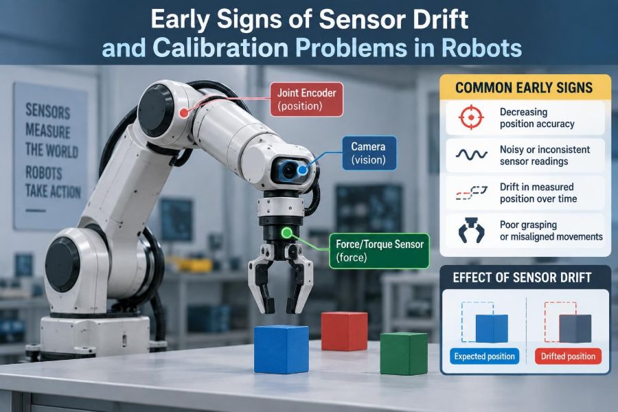

A mobile robot completes the same warehouse route every morning. Then, over several shifts, it begins stopping slightly short of docking points, taking wider turns, or rejecting perfectly valid packages as misplaced. Nothing appears broken. The robot still moves, sees, and reports data.
That quiet change is often more revealing than an abrupt fault. Robots depend on sensors to connect software decisions to the physical world, and when measurements slowly stop representing reality, behavior can degrade long before a safety interlock or error code appears.
Sensor drift and calibration problems affect simple classroom platforms, collaborative arms, drones, autonomous vehicles, and industrial inspection systems. They can lower quality, create confusing intermittent failures, and, in safety-critical work, leave too little margin for reliable operation.
The useful skill is not merely knowing how to recalibrate a device. It is learning to recognize the small mismatches between what a robot expects to sense and what it actually senses—and then isolating the source methodically.
🧭 What Sensor Drift Actually Means
Sensor drift is a gradual change in a sensor’s output when the real quantity being measured has not changed by the same amount. A stationary gyroscope may slowly report rotation, for example, or a pressure sensor may increasingly report a different force under the same load.
Drift is not always a permanent fault. Temperature, power conditions, warm-up state, aging, contamination, and mechanical stress can all shift a measurement temporarily or over time. The defining clue is that the sensor’s relationship to reality has moved.
🎯 Calibration Is the Measurement Agreement
Calibration establishes the relationship between a sensor reading and a known reference. For a camera, that may include focal length, lens distortion, and its pose relative to the robot. For a force sensor, it may include zero offset and sensitivity across a defined load range.
A sensor can be electrically healthy yet poorly calibrated. It may deliver stable, repeatable numbers that are consistently wrong, which makes calibration problems especially difficult to spot through casual observation.
🔍 Drift, Noise, and Failure Are Different Problems
These terms are often mixed together, but they lead to different diagnostic choices. Noise is short-term random variation; drift is a changing bias or scale; a failure is usually an abrupt loss, implausible output, or missing communication.
| Pattern | What it looks like | Useful first check |
|---|---|---|
| Noise | Readings scatter around a stable average | Sampling, shielding, filtering, vibration |
| Bias drift | Average reading slowly shifts | Temperature, warm-up, zero reference |
| Scale error | Error grows with distance, force, or speed | Multi-point calibration |
| Hard fault | Dropouts, fixed values, impossible jumps | Cabling, power, communications, hardware |
A filter can make noisy data look smooth, but it cannot make a biased measurement true. Smoothing a drifting sensor may hide the symptom while allowing the robot to make increasingly incorrect decisions.
📈 The First Clue: Repeatable Work Starts Varying
Many early warnings appear as a loss of repeatability. A robot arm that once inserts a peg reliably might occasionally brush an edge. A vehicle that normally centers itself in a corridor may favor one side.
Record the task conditions before blaming the sensor. If the part fixture, lighting, floor surface, payload, or tool has changed, the apparent sensor issue may be an altered environment. If conditions are controlled and the error grows, calibration deserves closer attention.
📍 Growing Position Error After a Known Move
A clear field symptom is when commanded motion and observed position no longer agree. After driving a known straight distance, a mobile platform may consistently stop too early. After a robot arm moves to a taught pose, its end effector may miss a fixed reference.
The error pattern matters. A nearly constant miss suggests an offset. A miss that increases with travel suggests wheel diameter, encoder scale, kinematic parameter, or timing errors. The sensor is one candidate within a larger measurement chain.
🧲 A Robot That Slowly Loses Its Heading
Heading drift is especially visible in robots that integrate gyroscope data to estimate orientation. Even a small angular-rate bias accumulates into a larger angle error because the system continually adds measured rotation over time.
A robot may begin a run facing the correct direction and finish apparently “confident” but rotated relative to walls, map features, or a docking marker. If the heading improves whenever visual landmarks are available, the inertial estimate may be drifting between corrections.
🛞 Unexpected Curves During Straight Travel
A differential-drive robot that arcs during a straight command is not automatically suffering from bad wheel encoders. Unequal tire wear, different wheel contact, a loose hub, drag in a gearbox, and uneven load distribution can create the same behavior.
Still, encoders are part of the investigation. Compare left and right tick counts, inspect wheel radii, and repeat the test in both directions on a consistent surface. Direction-dependent error often points toward backlash, friction, alignment, or asymmetric mechanics rather than a simple encoder offset.
🌡️ Errors That Follow Temperature
If measurements are accurate shortly after startup but shift after the robot operates for a while, temperature dependence is a strong suspect. Electronics, optical components, strain gauges, batteries, and mechanical mounts can all change behavior as they heat.
Trend sensor values alongside board or enclosure temperature during a controlled test. Do not assume the temperature sensor itself identifies the cause; it is a useful correlation signal. The relevant component may be warmer or cooler than the reported location.
⏳ Warm-Up Behavior Is Useful Evidence
Some sensors and analog circuits need time to settle after power-up. A repeatable warm-up period is not automatically unacceptable, provided the robot’s operating procedure accounts for it and the system remains safe while estimates stabilize.
The warning sign is undocumented or changing warm-up behavior. If yesterday’s stable offset becomes today’s large, irregular shift, investigate supply voltage, mounting stress, environmental exposure, and component degradation rather than simply extending the wait time.
👁️ Vision Systems That Misjudge Distance or Pose
Vision calibration trouble often appears as overlays that look correct near the image center but diverge at the edges, or as grasp points that are accurate at one height and wrong at another. Lens distortion, focus changes, camera mounting, and coordinate transforms can each contribute.
A camera may also be calibrated internally but misregistered to the robot. This is an extrinsic calibration error: the system knows how the camera sees pixels but has the wrong estimate of where the camera sits relative to the arm, base, or tool.
💡 Lighting Changes Can Imitate Calibration Errors
Changing illumination can alter a camera’s exposure, contrast, glare, and apparent feature boundaries. A barcode reader, depth camera, or color classifier may begin failing at a particular time of day without any geometric calibration changing.
Separate perception robustness from calibration by testing a known target under controlled light. If measured geometry changes with illumination, review exposure controls, target material, reflective surfaces, and the vision algorithm before repeatedly recalibrating the camera.
📏 Range Sensors With a Moving Zero Point
Ultrasonic, infrared, laser, and time-of-flight sensors can develop offset-like behavior. A robot that normally stops a safe distance from a wall may creep closer or stop farther away even though the wall has not moved.
Check several known distances, not just one. A constant discrepancy is different from a nonlinear response, and both differ from occasional invalid returns caused by target angle, transparent material, reflectivity, dust, or cross-talk from another range sensor.
🧹 Dirty Optics Create Quiet Measurement Changes
Dust, oil mist, fingerprints, water droplets, and scratched protective windows reduce or distort optical signals. The effect may be gradual enough that a robot continues operating while confidence scores, detection range, or depth quality deteriorate.
Cleaning must follow the manufacturer’s material and handling guidance. Aggressive solvents or abrasive wiping can damage coatings and make a temporary issue permanent. Inspect seals and airflow too; repeated contamination is a maintenance-system problem, not just a cleaning task.
⚖️ Force and Torque Sensors That Will Not Return to Zero
A force/torque sensor should be evaluated when unloaded and after a known load is removed. If its zero reading does not return within the expected operating tolerance, the cause may be thermal drift, cable strain, overload history, fixture preload, or a software tare applied in the wrong state.
Do not casually re-zero a sensor while a tool is touching a surface. That can hide real contact force and defeat collision or insertion logic. Establish a documented unloaded pose and confirm that cables and hoses are not exerting unnoticed force.
🧪 Bias Versus Sensitivity: Test More Than One Point
A single reference check tells you whether a reading is right at one condition. It does not reveal whether the sensor’s scale is correct across its operating range. A scale error may look harmless near zero but become significant during larger motion or load.
Use multiple known references where practical: several distances for a range sensor, several loads for a force sensor, or several orientations for an inertial sensor. Plotting error against the reference often reveals whether the issue is offset, gain, nonlinearity, hysteresis, or a changing environment.
📡 Intermittent Data Is Not Always Drift
Brief spikes, stale values, or irregular update intervals can destabilize a control loop and resemble a bad calibration. Common causes include loose connectors, electromagnetic interference, bus congestion, clocking problems, dropped packets, and inadequate grounding.
Inspect timestamps as well as values. A sensor that reports a plausible measurement late can be as dangerous to fast control as one that reports an incorrect measurement on time. Diagnostics should track communication health, sequence gaps, and data age.
🔋 Power Supply Changes Affect Measurements
Voltage ripple, ground offsets, poor regulator performance, and shared high-current loads can influence analog sensors and reference circuits. The pattern may emerge only when motors accelerate, a gripper closes, or a pump switches on.
Compare sensor behavior during quiet and high-load operating states. A relationship to actuator activity points toward electrical coupling or power integrity. This diagnosis requires safe measurement practice, especially around industrial power equipment; use qualified personnel and appropriate tools.
🪛 Mechanical Shifts Break Frame Relationships
Calibration depends on physical geometry staying fixed. A camera bracket that slips by a small amount, a lidar mount that twists, or an arm tool that is replaced without updating its tool-center point can invalidate otherwise excellent calibration data.
Look for loose fasteners, damaged locating pins, worn couplings, cable tension, and impacts. Marked fasteners, keyed interfaces, torque procedures, and post-service verification reduce the chance that a mechanical change becomes a mysterious software problem.
🧮 Coordinate Frames Cause Many “Sensor” Bugs
Robots use coordinate frames to express position and orientation: world, base, joint, tool, camera, map, and more. A sign error, wrong rotation order, outdated transform, or mismatched unit can create behavior indistinguishable from sensor miscalibration.
Use a simple physical test. Place a target at a known location and trace its coordinates through each transform. Verify frame names, units, timestamps, and conventions explicitly. A correct sensor value transformed incorrectly is still an incorrect value for the controller.
🕰️ Time Synchronization Matters for Moving Robots
When a robot fuses camera, lidar, encoder, and inertial data, each observation needs a meaningful timestamp. If sensor clocks differ or data arrives with variable delay, the system may combine measurements from different physical moments.
This creates apparent spatial misalignment that grows with speed. A stationary bench test can pass while a moving robot fails. Check time bases, latency estimates, buffering, and whether transforms are requested for the measurement time rather than the latest available pose.
🧠 Sensor Fusion Can Hide a Weak Sensor
Sensor fusion combines measurements so that one source can correct another. It is powerful, but a stable-looking fused estimate does not prove each input is healthy. A map match may mask gyro drift, while a faulty wheel encoder may be hidden by vision until the camera is obscured.
Log and inspect innovation or residual behavior where the estimator provides it: the difference between a predicted measurement and an actual one. Persistent, structured residuals can identify a sensor or model that no longer agrees with the rest of the system.
🧷 Use Independent References Carefully
Calibration checks need a reference that is more trustworthy than the sensor under test for the intended task. This might be a surveyed fiducial, a gauge block, a calibrated weight, a straight test path, or a second measurement system with understood uncertainty.
Independence matters. Comparing a camera to a robot pose estimated partly from that same camera can create false confidence. A reference also has limits, so document its condition, setup, and expected accuracy rather than treating it as perfect.
🧾 Establish a Baseline Before Trouble Appears
The best diagnostic data is often collected when the robot is known to work well. Save calibration files with version information, raw sensor snapshots, environmental conditions, reference-test results, and photos of critical mounting arrangements.
Baselines turn subjective reports such as “it seems off” into comparisons. They also help distinguish gradual drift from a sudden change after maintenance, a software update, an impact, a new payload, or a seasonal environmental shift.
📊 Trend the Right Health Indicators
Raw values alone are rarely enough. Trend task-level errors and quality indicators such as docking offset, reprojection error in vision calibration, range-sensor confidence, force zero, estimator residuals, rejected detections, and time since last successful reference check.
Set review thresholds according to the robot’s safety and accuracy needs, not arbitrary universal numbers. A small pose error may be acceptable for floor cleaning but unacceptable for precision assembly or close human-robot collaboration.
🧰 A Disciplined Diagnostic Sequence
When behavior changes, avoid adjusting several settings at once. That can restore performance temporarily while destroying the evidence needed to find the cause. Work from simple external checks toward calibration and replacement.
- Make the robot safe and record the symptom, task, time, software version, and environment.
- Inspect mounts, targets, lenses, connectors, cable routing, and recent mechanical changes.
- Repeat a controlled reference test and log raw values with timestamps.
- Check power, communications, timing, and temperature correlations.
- Compare against a baseline and isolate one sensor or transform at a time.
- Recalibrate only after the physical and software conditions are understood.
- Validate the result with an independent task-level test.
🚫 Common Recalibration Mistakes
Recalibration is not a reset button. Performing it on an unlevel surface, with a dirty target, a moving mount, an unrepresentative payload, or unstable lighting can store a worse model than the one it replaces.
- Using a single test point to approve a full operating range.
- Accepting calibration residuals without checking where the errors occur.
- Overwriting the previous calibration without versioning or rollback.
- Changing filters, controller gains, and calibration together.
- Taring force sensors while external contact or cable force is present.
Keep the prior validated configuration and record the procedure. Reproducibility is part of calibration quality.
🔁 Verification Must Match the Real Task
A calibration routine can report success while the application still fails. The routine may optimize a limited geometry or range that does not represent the actual workspace, speed, payload, illumination, or surface material.
After calibration, run representative checks: approach a dock from multiple angles, inspect targets across the camera field, execute motions across the arm workspace, or test range readings on the materials the robot actually encounters. Verify both accuracy and repeatability.
🛡️ Safety Systems Need Conservative Assumptions
Where sensor errors influence collision avoidance, speed limits, force limits, or human proximity detection, drift management belongs in the safety strategy. A maintenance check alone may not be enough if an error can develop between inspections.
Use suitable redundancy, plausibility checks, degraded modes, and fault responses for the application. The exact design depends on the robot, risk assessment, standards, and operating environment. Calibration should never be treated as a substitute for a properly engineered safety function.
🗓️ Build Calibration Into Maintenance Workflows
Calibration intervals should reflect actual exposure and performance history. A sealed indoor robot may need different checks from a machine exposed to vibration, washdown, dust, temperature swings, frequent tool changes, or impacts.
Trigger checks after meaningful events as well as on a schedule: a collision, sensor replacement, mount adjustment, firmware change, battery or power-system work, or a persistent deviation in monitoring data. Event-based verification catches problems that calendar-only plans can miss.
🤝 Know When to Escalate the Problem
Escalate when a sensor cannot meet the required uncertainty after proper setup, when output changes unpredictably, when physical damage or overload is suspected, or when the issue affects a safety-related function. Continuing to compensate in software can increase uncertainty and obscure a developing hardware problem.
For proprietary industrial systems, use the approved service procedure and manufacturer support channels. For custom systems, preserve logs, calibration artifacts, environmental notes, and test setups so another engineer can reproduce the observation efficiently.
🧭 The Core Principle: Trust Measurements, But Verify Them
Early detection comes from comparing the robot’s internal estimate with controlled reality. Small, repeatable discrepancies are valuable signals: they reveal whether a measurement is changing, whether a frame relationship has moved, or whether the environment is challenging the sensing method.
The strongest practice combines clean mechanical installation, stable power and timing, versioned calibration, independent reference checks, and task-level validation. That approach avoids the two costly extremes: ignoring subtle drift and recalibrating blindly every time behavior changes.
A robot remains accurate not because its sensors are assumed correct, but because its measurements are routinely tested against the real world they are meant to describe. 🦾📐🔎