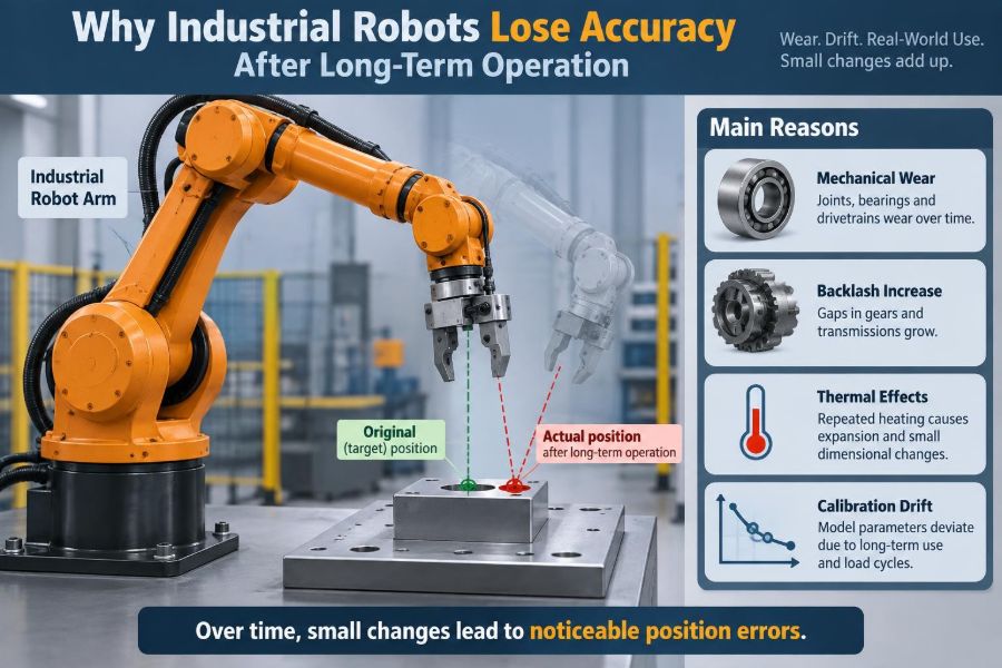

A robot cell can run smoothly for years and still begin producing parts that are slightly wrong. A weld lands a little off-center. A palletizing gripper approaches a carton with less confidence. A machining robot reaches the right general area but misses a tight-tolerance feature.
These problems rarely arrive as a dramatic failure. More often, operators compensate: they shift a fixture, touch up a taught point, slow the motion, or accept a wider process variation. Eventually, those small corrections become routine—and the original source of the error becomes harder to see.
Long-term accuracy loss matters because industrial robots are usually part of a larger system. A few millimeters of positional change can affect assembly fit, weld quality, adhesive placement, inspection results, cycle time, and unplanned downtime.
Understanding why accuracy changes over time helps teams separate normal mechanical aging from programming, tooling, environmental, and measurement problems. It also leads to better maintenance decisions than simply reteaching every point.
🎯 Accuracy Is Not a Single Robot Property
When someone says a robot is “less accurate,” they may mean several different things. Pose accuracy is how closely the robot’s actual position and orientation match the commanded target in space. Orientation matters because a tool can arrive at the correct location while pointing a weld gun, dispenser, or gripper incorrectly.
Accuracy also depends on the entire process: the robot, end-of-arm tool, fixture, part, vision system, and coordinate frames. A robot may be mechanically healthy while the production result is inaccurate for another reason.
🔁 Repeatability Can Hide a Growing Problem
Repeatability describes how consistently a robot returns to the same pose when it repeats the same command. A robot can be highly repeatable but not very accurate in an absolute sense.
Imagine throwing darts into a tight cluster that is several centimeters away from the bullseye. The throws are repeatable, but not accurate. This distinction explains why a robot may continue to perform an old task reliably while struggling after a fixture change, offline-program conversion, or new product introduction.
📏 The Robot’s Published Specification Has Limits
Robot catalogs usually state performance under defined test conditions, often near nominal payload and speed ranges. That value is not a permanent promise that every point in every production cell will remain within the same error band indefinitely.
Reach, posture, payload, acceleration, mounting stiffness, temperature, and calibration all influence the result. Treat a catalog specification as a useful engineering reference, not a substitute for process capability testing in the actual cell.
🧭 Calibration Defines the Robot’s Internal Map
A robot controller calculates tool position from encoder readings and a mathematical model of link lengths, joint offsets, and axis geometry. Calibration establishes the relationship between those measurements and the physical mechanism.
If this internal map is imperfect, the robot can move consistently according to its model while its real tool center point is displaced. Calibration-sensitive applications include coordinated robots, rail-mounted robots, precise drilling, robotic machining, and offline programming.
⚙️ Joint Backlash Creates Direction-Dependent Error
Backlash is small free movement between mating components before torque is transferred in the opposite direction. In a robot joint, it can arise in gears, reducers, couplings, splines, bearings, or mechanical interfaces.
The classic symptom is a robot that reaches a point differently depending on the direction of approach. A taught position may look correct when approached from one path but shift after a reversal. This is especially troublesome in processes that alternate direction or make fine corrective moves.
🪛 Gear Reducer Wear Changes the Transmission
Most articulated robots use compact, high-ratio reducers to convert motor motion into controlled joint motion. These components operate under repeated torque, reversal, and shock loads. Over long service periods, contact surfaces and internal clearances can change.
Wear does not always mean immediate failure. It may first appear as increased lost motion, vibration, noise, temperature rise, or a gradual change in path quality. Heavy payloads, frequent hard reversals, and collisions can accelerate the process.
🛢️ Lubrication Is Part of Positioning Performance
Lubricant reduces friction and wear inside joints and gearboxes, but its condition also affects motion behavior. Aging grease can separate, migrate, become contaminated, or lose properties needed for a particular load and temperature range.
Using the wrong lubricant or service interval can create problems that look like servo tuning errors. Maintenance must follow the robot manufacturer’s approved materials and procedures; mixing products without confirmation can damage seals or compromise gearbox behavior.
🧱 Bearings and Structural Stiffness Matter
A robot arm is not perfectly rigid. Links, bearings, wrist components, and the base all deflect under load. As bearings wear or preload changes, the arm may exhibit greater compliance—small shifts under force that disappear when the load is removed.
This matters in machining, deburring, press tending, and force-controlled assembly. A robot that positions well in free space may deviate when a cutting tool engages a part or when a gripper pushes a component into a tight fit.
🏋️ Payload Creep Changes Deflection
The robot’s rated payload includes more than the mass of the tool. It also includes parts, hoses, cables, adapters, fasteners, and any carried product. Just as important is the center of gravity, which determines the torque applied to each axis.
A tool may gain only a little mass after a redesign, yet its center of gravity may move farther from the wrist. That extra moment can increase static sag, dynamic overshoot, and joint loading. Update payload data whenever the end effector changes.
🚀 Aggressive Motion Amplifies Small Weaknesses
High speed alone is not always the problem. High acceleration, abrupt deceleration, and repeated reversals generate larger dynamic forces. A path that looks accurate at reduced speed can drift, vibrate, or overshoot at production settings.
If accuracy deteriorates mainly during fast motion, inspect motion profiles, payload settings, mechanical stiffness, and servo condition before assuming that a taught point is wrong. Slowing the robot may contain the symptom, but it can conceal a developing mechanical issue.
🌡️ Temperature Changes Geometry and Control Behavior
Motors, reducers, grease, castings, tools, fixtures, and the surrounding structure expand or contract as temperatures change. The resulting movement may be small, but precision processes can be sensitive to it.
A robot may behave differently at the beginning of a shift than after hours of continuous production. Heat from welding, machining, nearby ovens, or direct sunlight can add localized effects. Warm-up routines and measurement at normal operating temperature can make evaluations more meaningful.
❄️ Cold Starts Can Produce Misleading Measurements
At low temperatures, lubricants can be more resistant to motion and mechanical clearances can differ from their stabilized state. The controller may still operate normally, yet path behavior can change during the first cycles.
Do not judge long-term accuracy from a single cold-start test if the process normally runs hot. Record ambient conditions, robot run time, and tool temperature alongside the measurement result.
🏭 The Cell Floor Is a Harsh Environment
Dust, abrasive particles, weld spatter, coolant mist, metal chips, humidity, and chemical vapors can affect seals, connectors, cables, brakes, and exposed tooling. Environmental damage often begins outside the robot’s main arm and then appears as intermittent or gradual process variation.
Protective covers, correct ingress protection, routine cleaning, and cable inspection are practical accuracy controls—not just housekeeping. A contaminated fixture locating pin can create as much error as a worn robot joint.
💥 Collisions Can Shift More Than a Taught Point
A collision can damage a tool, bend a bracket, disturb a fixture, overload a gearbox, or alter a calibration relationship. Some effects are obvious, while others are subtle enough that production resumes after a quick visual check.
After a meaningful impact, inspect the entire affected chain: robot joints, flange, tool, cables, fixtures, safety devices, and calibration status. Retouching one target without investigation risks teaching around a damaged system.
🔌 Cables, Hoses, and Dress Packs Apply Hidden Forces
An external dress pack can pull on the wrist or snag at certain arm postures. Internal harnesses also age through flexing. These forces may create posture-specific deviation, especially near the limits of motion.
Watch the robot slowly through the problematic path. Look for hoses tightening, cable bundles rubbing, or a dress pack that changes shape as axes rotate. The best route allows movement without imposing a changing side load on the tool.
🧰 End Effectors Wear Too
Grippers, welding torches, dispensers, cutters, compliance units, and quick changers all have their own wear mechanisms. Jaws can loosen, nozzles can clog or bend, tool changers can develop play, and locating features can wear.
Because the tool is where the process happens, tool wear is often mistaken for robot inaccuracy. Verify the tool center point—the programmed reference point on the end effector—before diagnosing the arm itself.
📐 Tool Center Point Errors Multiply Downstream
A small error in tool center point definition affects every program position using that tool. If a torch is replaced, a gripper is repaired, or a spindle is remounted, the old tool data may no longer represent physical reality.
For example, a hypothetical 2 mm shift at the tool flange can become a visible error at a long nozzle tip. Use an appropriate TCP verification routine after service, and document the method so different technicians obtain comparable results.
🗺️ Base Frames and Work Objects Can Drift
Robots work through coordinate systems. A base frame describes the robot’s reference, while a work frame or work object describes the part, fixture, conveyor, or process area. If a fixture moves, a pallet is replaced differently, or a robot base settles, those frames no longer match reality.
Frame errors often affect all points in one area similarly. By contrast, a joint or tool problem may vary with posture. This pattern is useful when narrowing the fault.
🧲 Fixtures Are Often the Real Source of “Robot Error”
A robot can only place a part accurately relative to the reference it receives. Worn nests, bent clamps, debris under locating surfaces, inconsistent pneumatic pressure, and poorly constrained workpieces all produce variation.
Before adjusting robot positions, check whether the part is seated and clamped in the same way every cycle. A gauge, dial indicator, or simple repeatability study of the fixture can prevent hours of unnecessary robot troubleshooting.
👁️ Vision Systems Need Their Own Calibration
Robot-guided vision adds another coordinate transformation between camera, robot, and part. Camera movement, lens contamination, lighting changes, damaged targets, or altered mounting hardware can introduce errors even when the robot repeats perfectly.
Hand-eye calibration should be treated as controlled production data. If a camera or robot base is disturbed, confirm the calibration rather than compensating with an unexplained vision offset.
📡 Encoders and Feedback Devices Can Degrade
Encoders report motor or joint position to the controller. Faults may show up as alarms, but early issues can be intermittent: unstable feedback, intermittent connector contact, electrical noise, or battery-related loss of position data on some systems.
These faults require careful diagnosis by qualified personnel. Encoder and servo work may involve high voltages, stored energy, and manufacturer-specific recovery procedures. Do not treat unexplained position faults as a routine reteach task.
🎛️ Servo Tuning Is a Balance, Not a Maximum Setting
Servo control continuously compares commanded motion with feedback and applies torque to reduce error. Gains that are too low can allow sluggish tracking; gains that are too high can create oscillation, noise, or mechanical stress.
Modern robot controllers often manage this well within approved configurations, but changes to payload, process forces, or mechanics can expose limitations. Servo tuning should be based on manufacturer guidance and measured behavior, not trial-and-error adjustments on a production cell.
📊 Recognize Error Signatures Before Making Changes
The way an error appears is often more informative than its size. Capture the robot pose, approach direction, payload, speed, temperature, part condition, and time in service when the issue occurs.
| Observed pattern | Possible source to investigate |
|---|---|
| Same offset at many nearby points | Work frame, fixture, base reference, or vision transform |
| Different result by approach direction | Backlash, compliance, friction, or cable force |
| Error grows at high speed | Payload data, dynamics, stiffness, servo tracking, or dress pack |
| Error changes after warm-up | Thermal growth, lubrication behavior, or process heating |
| Only one tool or product is affected | TCP, end effector, program data, or product fixture |
These are diagnostic clues, not proof. Several causes can exist at once.
🧪 Measure Against a Stable Reference
Good diagnosis begins with measurement that is more reliable than the suspected error. Depending on the tolerance, teams may use calibrated artifacts, dial indicators, laser-based systems, ball bars, probing routines, or metrology equipment.
Use a stable reference and a repeatable test sequence. Measure several positions and orientations, not only the point where production first showed a problem. One-point checks can miss posture-dependent errors.
📝 Trend Data Reveals Slow Degradation
A single inspection says whether a system is acceptable at that moment. A history of comparable inspections can reveal whether it is stable, drifting, or changing after specific events such as collisions, tool replacements, or lubrication service.
Useful records include calibration results, TCP checks, reducer service, alarm history, crash reports, payload changes, fixture repairs, and quality measurements. Trends turn maintenance from reaction into planning.
🔧 Retouching Points Is Sometimes Correct
Retouching is appropriate when the physical process reference has intentionally changed—for example, after a verified fixture redesign or a controlled product update. It can also be a short-term production measure while a known repair is scheduled.
But a point change should have a recorded reason. If many points need repeated adjustment, the likely issue is systemic: frame data, calibration, tool geometry, fixture behavior, or mechanics.
🚫 Common Shortcuts That Make Accuracy Worse
Several common responses solve today’s symptom while weakening tomorrow’s diagnosis:
- Changing multiple offsets at once, making the original cause impossible to isolate.
- Teaching around a collision without inspecting the tool, fixtures, and affected axes.
- Using a different payload value without measuring the full tool assembly.
- Testing only at low speed when the defect occurs at production speed.
- Comparing measurements taken at different temperatures or with different parts.
- Ignoring fixture cleanliness because the robot appears to be the obvious suspect.
Controlled changes, one variable at a time, are slower at first and faster overall.
🛠️ Build Accuracy Into Preventive Maintenance
Preventive maintenance should combine manufacturer-required service with process-specific checks. The right interval depends on utilization, payload, environment, process forces, and tolerance requirements.
- Inspect external cables, hoses, dress packs, and tool mounting hardware.
- Verify lubrication condition and service intervals as specified by the manufacturer.
- Check fixture location, clamp condition, and contamination control.
- Confirm TCP and critical work frames after tool or fixture work.
- Review collision events and investigate unexplained quality changes.
- Perform periodic accuracy or repeatability checks against a documented baseline.
For tight-tolerance cells, these checks belong in the quality plan, not only the maintenance plan.
🧠 Design Cells for Diagnoseability
The easiest robot cell to maintain is one designed to make errors visible. Provide access to fixtures and tools, include durable datum features, route dress packs predictably, and preserve known verification poses.
Clear naming for tools, frames, programs, and revision-controlled backups prevents data mistakes from masquerading as mechanical drift. A small amount of design discipline can dramatically shorten troubleshooting after years of operation.
🤝 Know When to Escalate the Problem
Repeated calibration loss, suspected reducer damage, abnormal noise, unexpected heat, brake concerns, or unexplained encoder faults deserve escalation to trained maintenance staff or the robot manufacturer’s service resources. Continuing operation can turn a manageable repair into a larger failure.
Safety comes first. Follow lockout/tagout procedures, support arms correctly where required, and use authorized methods for mastering, brake release, and axis service. Precision work is never a reason to bypass safeguarding.
✅ The Core Principle: Accuracy Is a System Condition
Industrial robots lose effective accuracy over time because the real system changes. Mechanical wear, thermal effects, altered payloads, cable forces, damaged tools, shifting fixtures, calibration data, and measurement mistakes can all move the final process result.
The most reliable response is not to assume the robot is at fault or to reteach points immediately. Start with a stable measurement, identify the error pattern, inspect the full chain from base to workpiece, and correct the underlying cause before updating program data.
A robot remains accurate when its mechanics, calibration, tool, fixture, environment, and verification process are maintained as one connected system.