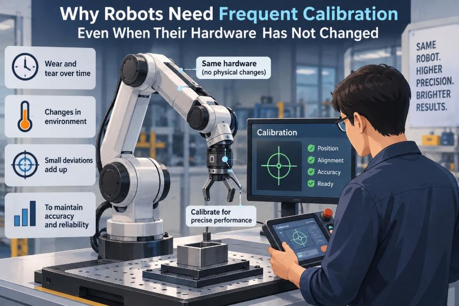

A robot may look exactly the same as it did last week: the same arm, camera, gripper, fixtures, and program. Yet a part that was placed perfectly on Monday can be misaligned by Friday.
This is a familiar puzzle in factories, laboratories, warehouses, and research labs. If nobody replaced the motor, moved the camera, or edited the code, why should the robot need attention?
The answer is that robotic accuracy depends on much more than intact hardware. It depends on the continuing agreement between sensors, coordinate systems, mechanical motion, and the real physical workspace.
Calibration is the process of checking and restoring that agreement. It is less like repairing a broken machine and more like checking a measuring instrument before relying on its measurements.
🎯 Calibration Is About Trusting Position
Calibration establishes the relationship between what a robot believes and what is physically true. A controller may command an end effector to move to coordinates such as X, Y, and Z, but those numbers only have meaning when the robot’s model matches the real cell.
For a six-axis industrial arm, calibration can involve joint zero positions, link geometry, tool position, camera alignment, and the location of work fixtures. For a mobile robot, it may include wheel size, sensor mounting angles, and the transformation between a map and the vehicle body.
A robot can be mechanically healthy but geometrically wrong. That distinction explains why calibration remains necessary without an obvious hardware failure.
🧭 Robots Work Through Coordinate Frames
Robots describe locations through coordinate frames: mathematical reference systems with an origin and orientation. Common frames include the robot base, each joint, the tool center point, a camera, a conveyor, and a part fixture.
To pick a component seen by a camera, the system converts the component’s position from camera coordinates into robot-base coordinates, then into a motion path for the tool. Each transformation must be sufficiently accurate for the required task.
A small error in one frame can travel through the whole chain. The robot may consistently miss the same feature even though every individual sensor appears to be returning plausible values.
📏 Accuracy and Repeatability Are Not the Same
Repeatability means a robot can return to nearly the same position when it repeats the same command. Accuracy means that position is close to the intended real-world location.
A robot can have excellent repeatability and poor absolute accuracy. Imagine a dart player who lands every dart in a tight cluster, but the cluster is five centimeters from the bullseye. The throws are repeatable, not accurate.
This is why a production cell may run smoothly until a part must align with a tight tolerance, a new fixture is introduced, or vision data is used. Calibration primarily protects accuracy; repeatability alone cannot prove the robot is correctly referenced.
🌡️ Temperature Changes Geometry
Materials expand and contract as temperature changes. Steel, aluminum, plastics, cables, gearboxes, and structural supports do not all respond identically, so a robot system’s geometry can shift slightly during operation.
A robot arm that begins work cold may not place parts exactly as it does after hours of movement. Motors and gearboxes generate heat, while nearby welding, machining, or outdoor conditions can affect the surrounding structure.
Many systems tolerate these changes easily. In precision dispensing, metrology, semiconductor handling, or fine assembly, however, a small thermal shift may consume a meaningful portion of the available tolerance.
🧱 Mechanical Loads Create Elastic Deflection
Robot links and fixtures are stiff, not perfectly rigid. When a payload changes, gravity and acceleration bend structures by small amounts. The resulting displacement is called elastic deflection.
Consider a robot that uses a light vacuum cup during one shift and a heavy machining tool during another. Its joints may reach the same encoder values, but the actual tool tip can sit in a slightly different place under load.
Calibration cannot remove structural flexibility, but it can characterize consistent offsets. Better path planning, lower acceleration, payload compensation, and stiffer tooling may be needed when deflection changes during a task.
⚙️ Gearboxes and Transmissions Do Not Stay Perfectly Still
Motion reaches a robot joint through transmissions such as gears, belts, harmonic drives, ball screws, or reducers. These components can exhibit backlash, friction changes, compliance, and wear even when they remain fully serviceable.
Backlash is lost motion when direction reverses: the motor turns briefly before the output moves appreciably. Modern robots compensate for much of it, but compensation depends on assumptions that may drift over time.
The practical symptom is often direction-dependent error. A robot may approach a pin accurately from one side and miss from the other, especially after changes in load, speed, or temperature.
🔌 Encoders Measure Motion, Not Necessarily Reality
Joint encoders report the rotation or position of a motor or joint axis. They are essential, but they do not independently verify the final location of the robot’s tool in the workspace.
For example, an encoder can correctly report a joint angle while a flexible mount bends, a belt stretches, or a tool slips slightly in its holder. The controller sees a valid internal measurement, while the process sees an offset.
This is a broader engineering lesson: feedback is only as complete as the quantity being measured. Joint feedback is not a direct measurement of every possible source of end-effector error.
🛠️ The Tool Center Point Can Move
The tool center point, usually called the TCP, is the point the robot program treats as the business end of a tool. It might be a gripper fingertip, welding wire tip, suction cup center, screwdriver bit, or dispensing nozzle.
Tool changes, minor collisions, cleaning, replacement consumables, and ordinary handling can alter the TCP. A nozzle may be installed a fraction differently; gripper fingers may wear; a welding contact tip may be replaced.
Even when the arm itself is unchanged, the robot is no longer controlling the same effective point. TCP verification is therefore a routine production concern, not an admission that the robot is damaged.
🔩 End Effectors Wear Where Work Happens
End effectors interact directly with parts, and that interaction produces wear. Grippers can develop clearance, suction cups can deform, cutting tools shorten, and probe tips can accumulate residue.
Some of these changes affect only process quality. Others change geometry as well. A worn gripper finger may still close reliably but position a part differently relative to the robot flange.
A useful calibration plan distinguishes between the robot, the tool, and the process. Recalibrating an arm cannot correct a gripper whose contact surfaces have worn beyond their intended condition.
👁️ Cameras Need Their Own Calibration
A vision-guided robot relies on camera calibration to relate image pixels to real rays, distances, or surfaces. Lens distortion, focal parameters, and the camera’s pose relative to the robot all matter.
Lens calibration addresses the camera’s optical behavior. Hand-eye calibration establishes the spatial relationship between the camera and the robot, especially when a camera is mounted on the wrist or observes the workspace from a fixed location.
A camera can continue producing sharp images while its geometric calibration becomes inadequate. Sharpness is about visual appearance; calibration is about whether an image measurement corresponds to the correct physical location.
💡 Lighting Can Change What Vision Measures
Lighting does not usually move a camera, but it can shift the feature a vision algorithm detects. Reflections, shadows, exposure changes, and surface finish can alter an edge, centroid, or fiducial marker location.
This is especially relevant for shiny metal, transparent materials, dark parts, and adhesive inspection. The robot may receive a different measured target position because the image-processing result changed, not because anything mechanically moved.
Stable illumination, guarded optics, controlled exposure, and robust feature selection reduce this risk. They complement geometric calibration rather than replacing it.
🏭 Fixtures and Workcells Quietly Drift
The workpiece coordinate frame is often defined by a fixture, pallet, conveyor, or locating pins. Those objects experience vibration, impacts, cleaning, thermal cycles, and maintenance just like the robot does.
A fixture can remain firmly bolted down yet shift slightly through settling, clamp wear, or deformation. In a high-tolerance task, that small change can matter more than the robot’s own positional error.
Calibration should therefore ask, “Where is the part really located?” rather than only, “Where is the robot?” The production cell is one geometric system.
📦 Parts Are Not Perfect Reference Objects
Manufactured parts vary. Castings, molded pieces, flexible materials, and assembled products may differ in shape or location within their stated tolerances.
If a robot is taught against one sample part and later misses another, the cause may be part variation rather than calibration drift. Vision, probing, compliant tooling, or better datum strategies may be more appropriate than repeatedly changing robot coordinates.
This distinction prevents a common mistake: using calibration to hide a process-control problem. Calibration aligns known frames; it cannot make inconsistent parts identical.
🚚 Conveyors Add a Moving Reference Frame
Conveyor tracking combines robot motion with a moving part coordinate system. The controller depends on encoder counts, conveyor speed, trigger timing, and the relationship between the detection point and pick point.
Wheel slip, belt tension changes, encoder coupling issues, and small timing delays can create apparent robot errors. The arm may be accurately following the wrong estimate of where the part will be.
Regular checks of conveyor scale and synchronization are as valuable as arm calibration in these applications. The relevant question is whether the robot and conveyor still agree on time and distance.
🧪 Process Calibration Is Different From Geometric Calibration
Not all calibration concerns position alone. Process calibration checks whether the robot produces the intended physical result: a consistent weld, bead, torque, force, cut, or applied material volume.
A dispensing nozzle may be geometrically correct but deliver an inconsistent bead because viscosity, pressure, or temperature changed. A force-controlled assembly task may need sensor zeroing even when the TCP is accurate.
Separating these categories makes troubleshooting faster. Geometric calibration answers “where?” Process calibration answers “what happened when the tool got there?”
🧯 Collisions May Cause Subtle Offsets
A severe collision typically produces an alarm or visible damage. A minor bump may not. It can loosen a camera bracket, bend a thin tool, shift a fixture, or disturb a mounted sensor without stopping the system.
For this reason, many teams perform a verification check after an unexpected contact, emergency stop, dropped payload, or tool jam. The goal is not to assume failure; it is to establish whether the reference relationships are still valid.
Post-event verification is particularly valuable when the process has little tolerance for a bad first part.
🧹 Maintenance Can Change a Robot Cell
Maintenance is necessary, but it can change geometry. Removing guards, replacing a tool, adjusting a sensor bracket, retensioning a belt, or remounting a fixture may alter a reference relationship.
The person performing the work may restore every component carefully and still introduce a small offset. This is normal because real components have mounting clearances and contact surfaces are not mathematically perfect.
A disciplined handover includes a defined check after maintenance. It turns an uncertain assumption—“it should be the same”—into a recorded condition.
📉 Drift Usually Appears as a Trend
Calibration drift is often gradual. The first sign may be a rising rate of vision retries, more manual touch-ups, a growing need to adjust offsets, or inspection measurements trending toward one tolerance limit.
Recording these indicators helps teams recognize change before defects become obvious. A simple log of verification results, tool changes, ambient conditions, and corrections can reveal useful patterns.
Not every variation is drift. Random variation can come from parts, lighting, measurement noise, or the process itself. Trend data gives engineers a better basis for deciding what to investigate.
📊 Choose a Calibration Interval by Risk
There is no universal recalibration schedule. A low-speed palletizing robot with generous placement tolerances needs a different strategy from a robot inserting connectors or measuring delicate components.
| Condition | What it suggests | Useful response |
|---|---|---|
| Tight tolerance or safety-critical task | Small errors have immediate consequences | Frequent verification and defined acceptance limits |
| Frequent tool or fixture changes | Reference frames are regularly disturbed | Check TCP and work frames after each change |
| Stable, forgiving process | Minor offsets may not affect output | Use periodic checks and trend monitoring |
| Variable temperature or heavy payloads | Operating conditions alter geometry | Verify under representative conditions |
The best interval follows the consequences of error, observed stability, change frequency, and the ability to detect a bad result before it escapes.
✅ Verification Is Not Always Full Calibration
A full calibration can be time-consuming and may require specialized equipment or vendor procedures. Fortunately, many routine decisions only require verification: checking whether the system remains within an acceptable limit.
A robot might touch a known reference pin, inspect a calibration artifact with a camera, or place a test part into a gauge. If it passes, production continues. If it fails, a deeper calibration or mechanical investigation follows.
This layered approach is efficient because it reserves complex work for cases where evidence shows it is needed.
🧰 Common Calibration Methods
Methods depend on the robot and required accuracy. A teach pendant may guide an operator through TCP determination or frame teaching, while external metrology equipment can measure an arm’s pose more comprehensively.
Practical methods in robotic cells
- Touch-off methods: the robot contacts known points to establish a tool or fixture frame.
- Reference artifacts: gauges, pins, plates, or fiducials provide repeatable physical targets.
- Vision targets: patterned boards or coded targets support camera and hand-eye calibration.
- External measurement: laser trackers, photogrammetry, or precision instruments assess absolute performance.
- Software compensation: controller parameters correct measured, repeatable geometric deviations.
More sophisticated measurement is not automatically better. The method must be capable enough for the task and practical enough to perform consistently.
🧠 Calibration Data Must Be Managed Carefully
Calibration results become configuration data: TCP values, payload settings, camera matrices, frame definitions, compensation files, and acceptance measurements. Losing track of them can undo careful engineering.
Use clear naming, access control, backups, and revision records. A restored controller backup with old frame data can create confusion if the physical cell has since been updated.
Good records also help distinguish a genuine mechanical change from an accidental parameter edit. In robotics, digital configuration and physical setup are tightly connected.
🔍 Separate Sensor Error From Robot Error
When a robot misses a target, the arm is often blamed first. But the target may have been measured incorrectly, mounted differently, or presented at an unexpected time.
A structured diagnosis follows the information path: verify the reference artifact, inspect the fixture, test the sensor measurement, check coordinate transformations, then assess robot motion and tool geometry. This avoids adjusting offsets until the symptom disappears temporarily.
Correcting the wrong source can make a system look better on one test and worse in normal production.
🚫 Common Mistakes During Recalibration
Several habits make calibration less reliable than it should be:
- Calibrating with an unrepresentative payload, tool, or temperature condition.
- Using a worn or poorly defined reference target.
- Changing multiple parameters at once, making the true cause impossible to trace.
- Accepting a single successful test instead of checking several poses or approaches.
- Overwriting prior values without recording what changed and why.
- Using manual offsets repeatedly instead of investigating persistent drift.
These errors are understandable under production pressure. A repeatable checklist reduces dependence on memory and individual judgment.
🦺 Calibration Supports Safety, But Does Not Replace It
Accurate positioning can reduce risks such as a tool entering an unintended area or a mobile robot misjudging a docking location. Still, calibration is not a substitute for guards, safety-rated sensing, safe motion limits, risk assessment, or lockout procedures.
Calibration activities themselves can introduce hazards because they may require teaching motion, opening guarded spaces, or handling tools manually. Follow the robot manufacturer’s procedures and the site’s safety controls.
Safety functions should be validated through their own required processes. A robot that is well calibrated is not automatically safe, and a safe robot is not automatically accurate.
🤖 Mobile Robots Face a Different Drift Pattern
Autonomous mobile robots and automated guided vehicles must estimate where they are while moving through changing environments. Wheel wear, tire pressure, floor conditions, load distribution, and wheel slip can alter odometry, which is position estimated from wheel motion.
Localization sensors such as cameras, lidar, or markers can correct some of that accumulated error. But moved landmarks, dirty sensors, altered routes, and map changes may require remapping or recalibration.
The principle remains the same: the vehicle needs a reliable relationship between its internal estimate and its physical surroundings.
🧑🏭 Operators Are Part of the Measurement System
Operators often notice calibration problems first: a part that suddenly needs more force, a pick that looks slightly off-center, or a vision system that retries more often. Their observations are valuable process data.
Clear escalation rules help convert that insight into action. Define what should be logged, which checks an operator can perform, when an engineer should be called, and when production should pause.
Training should explain the reason behind checks, not only the button sequence. People are more likely to catch meaningful anomalies when they understand what a reference frame represents.
📈 Design Cells That Are Easier to Calibrate
Calibration burden can be reduced during design. Rigid mounts, protected camera brackets, accessible reference features, repeatable tool changers, stable lighting, and clear datums all make later verification simpler.
Designers should also consider whether a reference can be checked without dismantling equipment. A small, durable reference artifact placed in an accessible location can save substantial downtime.
There is a trade-off: extra sensors, fixtures, and metrology features add cost and complexity. They are most justified where process tolerance, change frequency, or defect consequences warrant them.
🗺️ A Sensible Calibration Workflow
A robust workflow makes calibration a controlled engineering activity rather than an emergency adjustment:
- Define what must be accurate: tool tip, camera measurement, part frame, force, or mobile localization.
- Choose a stable reference and measurable acceptance criteria.
- Verify the physical setup before changing software values.
- Calibrate or correct one defined relationship at a time.
- Validate at several representative positions, directions, speeds, and loads.
- Record results, parameters, conditions, and the reason for the intervention.
- Monitor later production to confirm the correction holds in real operation.
This process also reveals when calibration is not the right answer. A failure that returns quickly may point to looseness, wear, thermal behavior, or inconsistent incoming parts.
🏁 The Core Principle: Reality Keeps Moving
Robots are built from physical components operating in physical environments. Heat changes dimensions, loads bend structures, tools wear, sensors interpret changing scenes, fixtures settle, and maintenance alters relationships.
None of this means robots are unreliable. It means their internal mathematical model must be checked against the real world often enough for the task they perform.
Frequent calibration is not about distrust in the hardware; it is about maintaining trust between digital commands and physical reality.
When teams treat calibration as routine measurement, verification, and learning—not merely a response to failure—they catch drift earlier and make robotic systems more predictable, capable, and easier to improve. 🦾📏⚙️