
A small robot rolling across a desk seems simple—until it reaches a chair leg, a wall, or the edge of a book. A human sees the obstacle immediately. The robot needs hardware to detect it, software to interpret that detection, and motors that react before a collision.
That loop is the foundation of mobile robotics: sense, decide, and act. Building an obstacle-avoiding robot is a compact way to experience the entire loop without needing advanced tools or a complex mechanical design.
It also exposes the useful, imperfect reality of sensors. An ultrasonic module can report a distance, but soft fabric may absorb its sound, angled surfaces may deflect it, and motor noise can disrupt a marginal power supply. Those are not failures of the project; they are engineering lessons.
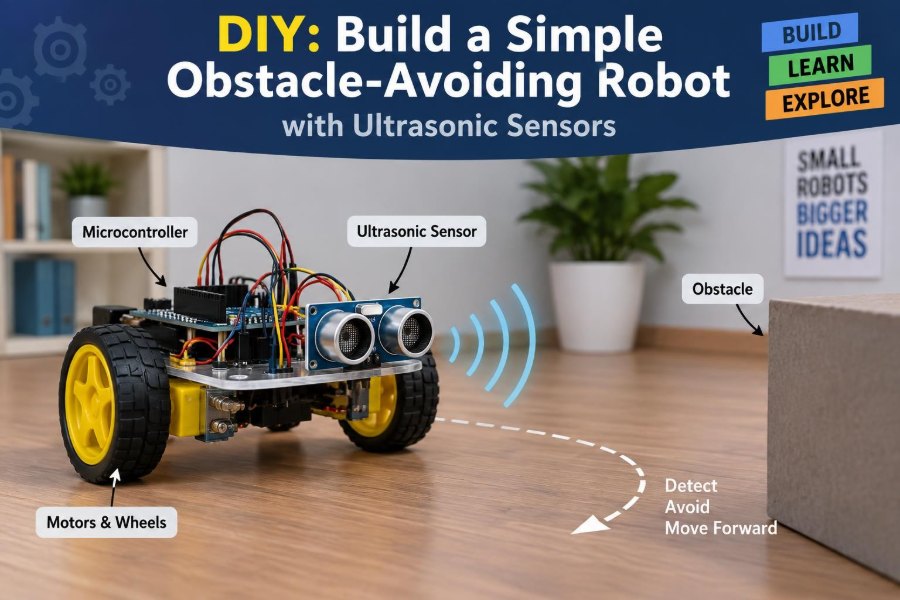
This build uses an Arduino-class microcontroller, an HC-SR04-style ultrasonic sensor, a motor driver, and a two-wheel chassis. The result is a robot that drives forward, notices nearby objects, stops, reverses briefly, and turns toward a clearer direction.
🤖 What the Robot Is Designed to Do
The basic robot has two driven wheels and usually a free-spinning caster wheel. It moves forward while periodically measuring the distance to whatever is in front of its ultrasonic sensor.
When the measured distance becomes smaller than a chosen safety threshold, the controller changes the motor commands. A simple first behavior is: stop, reverse, turn, then continue forward.
This is not mapping or true autonomous navigation. The robot does not know where it is in a room or remember every obstacle. It is a reactive robot: its immediate sensor reading determines its immediate action.
🔁 The Sense-Decide-Act Control Loop
Every useful mobile robot runs some version of a control loop. First it gathers information from sensors. Next it applies a decision rule. Finally it drives actuators—devices that create physical motion—such as motors.
For this project, the loop can be expressed simply:
measure distance
if obstacle is close:
  stop
  reverse
  turn
else:
  drive forward
The loop repeats continuously. A fast, well-structured loop makes the robot feel responsive; a slow loop lets it travel too far between measurements.
📡 How Ultrasonic Distance Measurement Works
An ultrasonic sensor uses sound above the usual range of human hearing. The module emits a short burst, then listens for the echo returning from an object.
The microcontroller measures the echo’s travel time. Because sound travels to the obstacle and back, the one-way distance is half the total path:
distance = (echo time × speed of sound) ÷ 2Many beginner libraries or code examples use a convenient conversion from microseconds to centimeters. That approximation is suitable for a small indoor robot, though temperature and air conditions slightly affect the speed of sound.
🧠 Why a Threshold Creates a Decision
A distance value becomes useful only when the robot has a rule for it. If your avoidance threshold is 20 cm, a measurement of 45 cm means “continue,” while a measurement of 15 cm means “avoid.”
The best threshold depends on speed, chassis size, floor grip, and turning ability. A quick robot needs more room to stop and rotate than a slow one.
Start conservatively. A threshold around 20–30 cm is often practical for a tabletop-sized beginner chassis, then adjust it during testing. The goal is not a universal number; it is enough clearance for your robot to react reliably.
🧰 Parts You Will Need
Choose components that match the voltage and current needs of your motors. A typical build uses the following:
- An Arduino Uno, Nano, or compatible microcontroller board
- A two-wheel-drive robot chassis with two DC gear motors and wheels
- A caster wheel or ball caster
- An HC-SR04 or compatible ultrasonic distance sensor
- An H-bridge motor driver module, such as an L298N or a suitably rated alternative
- A battery pack appropriate for the motors and driver
- Jumper wires, a small breadboard or connectors, and mounting hardware
- A USB cable for programming and a computer with the Arduino IDE
A small servo motor is optional. Mounting the ultrasonic sensor on a servo lets it scan left and right, which supports smarter turning decisions later.
🛞 Understand the Differential-Drive Chassis
Most simple robot kits use differential drive. The left and right wheels are powered independently, so steering comes from changing their directions or speeds.
| Left wheel | Right wheel | Result |
|---|---|---|
| Forward | Forward | Robot moves forward |
| Reverse | Reverse | Robot moves backward |
| Reverse | Forward | Robot spins in one direction |
| Forward | Reverse | Robot spins in the opposite direction |
| Stopped | Stopped | Robot stops or coasts, depending on driver behavior |
If a motor is installed as a mirror image of the other, its wiring may need to be reversed for “forward” commands to move both wheels in the same physical direction. Test each wheel before running the full program.
⚡ Why the Motor Driver Is Necessary
A microcontroller pin can send a logic signal, but it cannot safely provide the current required by DC motors. Motors also create electrical noise and voltage spikes when their magnetic fields change.
An H-bridge motor driver sits between the controller and motors. It accepts low-power direction and speed commands, then switches motor power in the requested direction.
Do not connect a DC motor directly to an Arduino output pin. At best, it will not work; at worst, it can damage the board. The driver is both a control interface and a protective necessity.
🔋 Plan Power Before Connecting Wires
Motors draw much more current when starting, turning, or stalled against an obstacle. A battery arrangement that powers the microcontroller on a desk may still sag when both motors move.
In many beginner builds, the motor supply feeds the driver and the controller is powered separately by USB during programming. Once the system works, a properly regulated shared battery arrangement can be used if the board and motor driver specifications allow it.
All control signals need a common reference. Connect the ground of the microcontroller to the ground of the motor driver. Without that shared ground, the driver may interpret the control signals unpredictably.
🧱 Assemble the Mechanical Base First
Secure the two gear motors to the chassis, press on the wheels, and mount the caster at the opposite end. Check that the chassis rests level and that neither wheel rubs against the frame.
Place the battery low and near the center when possible. A high or off-center battery pack makes the robot less stable and can reduce wheel traction during turns.
Mount the sensor facing forward with a clear field of view. Avoid placing a plate, wire bundle, or chassis edge directly in front of the sensor’s transmitters.
📍 Position the Sensor for Useful Measurements
The ultrasonic sensor should face roughly parallel to the floor. If it points downward, the floor may become the nearest “obstacle.” If it points upward, it may miss low objects such as blocks or baseboards.
Mount it high enough that its sound path clears the front bumper, but low enough to detect objects the chassis could hit. For a small robot, the sensor is commonly mounted near the upper front face.
Keep in mind that the sensing area is a cone rather than a laser-thin line. The robot may detect a wide object before it appears directly in front of the sensor.
🔌 Wire the Ultrasonic Sensor
An HC-SR04-style module typically has four pins: VCC, GND, TRIG, and ECHO. VCC and GND power the module. The controller briefly drives TRIG high to request a measurement, then measures the duration of the pulse on ECHO.
A common arrangement uses any two available digital pins for TRIG and ECHO. For example:
- VCC to the board’s 5 V output, if the module and board are both designed for 5 V logic
- GND to common ground
- TRIG to a digital output pin
- ECHO to a digital input pin
Check the logic voltage of your exact controller. A 3.3 V microcontroller may need a level-shifting or voltage-divider arrangement on an echo line that outputs 5 V.
🧷 Wire the Motor Driver Carefully
A dual-channel H-bridge has one output pair for each motor. Connect the left motor to one channel and the right motor to the other. Connect the motor battery to the driver’s motor-power input, observing polarity.
Then connect the driver’s direction inputs to four microcontroller digital pins. If your driver offers enable pins, connect them to PWM-capable pins when you want software speed control, or configure them as required by the module documentation.
Before adding the sensor code, write a tiny motor test sketch. Verify forward, reverse, left turn, right turn, and stop. Fixing swapped wires now is far easier than debugging everything at once.
🧾 Choose Clear Pin Names in Code
Readable code makes hardware troubleshooting faster. Instead of scattering pin numbers throughout a sketch, declare descriptive constants near the top.
const int trigPin = 9;
const int echoPin = 10;
const int leftForwardPin = 2;
const int leftReversePin = 3;
const int rightForwardPin = 4;
const int rightReversePin = 5;
The exact pin numbers are examples, not a required layout. Change them to match your wiring, then keep the names consistent throughout the program.
📏 Write a Distance-Reading Function
Encapsulate the sensor sequence in a function. The function sends a short trigger pulse, waits for the echo, converts time into distance, and returns the result.
long readDistanceCm() {
  digitalWrite(trigPin, LOW);
  delayMicroseconds(2);
  digitalWrite(trigPin, HIGH);
  delayMicroseconds(10);
  digitalWrite(trigPin, LOW);

  long duration = pulseIn(echoPin, HIGH, 30000);
  if (duration == 0) return -1;
  return duration * 0.034 / 2;
}
The timeout in pulseIn() prevents the program from waiting indefinitely when no usable echo arrives. Returning -1 creates a clear marker for an invalid measurement.
🚗 Create Reusable Motor Functions
Motor commands become easier to understand when they are grouped into functions such as moveForward(), moveBackward(), turnLeft(), turnRight(), and stopMotors().
Each function sets the four direction pins into the needed pattern. This separates what the robot should do from the lower-level pin settings that make it happen.
That separation matters when you change hardware. If you later reverse one motor’s wiring, you can correct the motor functions without rewriting the obstacle logic.
🧩 Build the First Avoidance Behavior
Your main loop can now combine sensing and motion. The following logic is deliberately basic, which makes it easy to test:
distance = readDistanceCm()
if distance is valid and distance < threshold:
  stop motors
  move backward briefly
  turn right briefly
else:
  move forward
The short delays determine how far the robot backs up and turns. They are not precise measurements of distance or angle because battery voltage, traction, and motor differences change the result.
Still, timed behavior is appropriate for a first build. It gives you a functioning robot before you add complexity.
⏱️ Use Delays Deliberately
Delays are convenient: a 300-millisecond reverse command creates a brief retreat, and a 450-millisecond turn creates a partial rotation. But while the controller is inside a long delay(), it is not taking new sensor readings.
For simple avoidance, short delays are usually acceptable. Avoid multi-second delays, which make the robot appear unaware of changes in its surroundings.
A more advanced version uses millis() to schedule actions without blocking the loop. That approach is valuable when you add indicators, multiple sensors, encoders, or communication.
🧪 Test One Subsystem at a Time
Do not begin by placing the complete robot on the floor and hoping it behaves correctly. Test in stages so each fault has a smaller set of possible causes.
- Print ultrasonic distance readings to the serial monitor.
- Move a flat object toward and away from the sensor.
- Test each motor direction with the wheels raised off the ground.
- Test forward motion on the floor.
- Add the obstacle threshold and observe the first avoidance cycle.
This workflow turns a vague “it does not work” problem into a specific wiring, code, power, or mechanics problem.
📊 Read Serial Data Before Trusting Motion
Use the serial monitor to print distance values while the robot is stationary. Test against a large, flat object at several distances and look for readings that are broadly stable.
Occasional variation is normal. A stream of zeros, extreme values, or repeated invalid readings indicates that you should inspect sensor wiring, sensor orientation, power, and code timing.
Printing measurements also reveals a common mistake: interpreting a failed reading as an object extremely close by. Treat invalid data as its own case rather than silently converting it into zero.
🧱 Real Obstacles Are Not All Equally Visible
Ultrasonic ranging works best when sound reflects back toward the sensor. A flat wall facing the robot is an easy target. A cushion, curtain, narrow chair leg, or slanted glossy panel can be harder to detect.
Soft materials absorb more sound. Rounded or angled surfaces can redirect echoes away from the receiver. Thin objects may not reflect a strong enough echo in the expected direction.
Design your testing course with ordinary household objects, but do not assume every object will be detected at the same range. This limitation is inherent to the sensing method.
🎚️ Reduce Noise with Multiple Readings
A single bad measurement can cause an unnecessary turn, while one missed echo can let the robot continue toward an obstacle. One straightforward improvement is to take several readings and use a robust summary such as the median.
For example, collect three or five valid distances, sort them, and use the middle value. The median is less influenced by one unusually large or small reading than a simple average.
Do not oversample without thought. Gathering many measurements adds response time, so choose a small number that improves stability without making the robot sluggish.
🛑 Add a Sensible Safety Margin
The robot should turn before contact, not at the exact edge of contact. The needed margin includes sensor update time, code execution time, motor response, coasting, and the physical length between the sensor and the frontmost part of the chassis.
If the sensor sits behind a bumper, the reported distance is measured from the sensor, not from the bumper. Account for that physical offset when selecting the threshold.
A good practical test is to increase speed gradually and raise the threshold until the robot consistently begins its avoidance action with room to spare.
↩️ Make Turning Less Predictable
Always turning right is easy to program, but it can trap the robot. In a corner or narrow corridor, it may repeatedly turn into another nearby surface and cycle in place.
A simple improvement alternates turn directions after each detected obstacle. Another option is to use a pseudo-random choice, while keeping the behavior reproducible enough for debugging.
Neither method guarantees escape from every geometry. It does reduce the tendency to repeat exactly the same unsuccessful move.
👀 Scan Left and Right with a Servo
For a more capable robot, attach the ultrasonic sensor to a small servo motor. When an obstacle appears ahead, the robot can pause, scan left, scan right, and turn toward the direction reporting more open space.
This does not create a full map. It simply gives the reactive controller two additional measurements at the decision point.
Allow the servo a moment to reach each target angle before measuring. Reading too soon can capture a distance while the sensor is still sweeping past the intended direction.
🗺️ A Simple Three-Direction Decision Rule
With a scanning sensor, compare front, left, and right distances. A useful rule is to drive forward when the front is clear; otherwise reverse slightly and choose the larger valid side distance.
Be careful with invalid readings. Depending on your environment, an invalid reading may mean open space beyond sensor range, a poor reflection, or a wiring problem. During development, log it rather than assuming it means “safe.”
A cautious strategy treats uncertain readings as a reason to slow down or rescan, especially near stairs, table edges, or other places where collisions are not the only hazard.
🏎️ Control Speed with PWM
Pulse-width modulation, or PWM, rapidly switches motor power on and off to create an adjustable average drive level. Many motor drivers expose enable inputs that can accept PWM signals from the microcontroller.
Lower speed gives the robot more time to sense and turn, and it often improves behavior on slippery floors. Higher speed makes the project more energetic but magnifies timing errors and stopping distance.
Speed control is also useful for turns. A robot may pivot more smoothly if one wheel runs slightly slower, though exact results depend on the chassis and surface.
🧭 Why Open-Loop Turns Drift
A timed turn assumes that a given motor command always produces the same angle. In reality, battery charge changes, one motor may be stronger, wheels may slip, and carpet behaves differently from tile.
This is called open-loop control: the controller sends an action without measuring whether the intended motion actually occurred. It is simple and often sufficient for a beginner obstacle avoider.
For repeatable movement, add feedback. Wheel encoders measure rotation, while an inertial sensor can estimate angular motion. Both add capability, but also calibration and software complexity.
🔧 Common Problem: The Robot Drives Backward
If “forward” sends the robot backward, do not immediately rewrite the entire program. First determine whether both motors are reversed together or only one is reversed.
If both wheels move backward, reverse the logic in your forward and reverse functions or swap both motor channel polarities. If one wheel moves opposite to the other, swap that motor’s two wires or correct only that side’s logic.
Make one change at a time and retest with the wheels off the floor. Randomly swapping multiple connections makes later diagnosis harder.
🔧 Common Problem: The Robot Resets or Stutters
A reset when motors start often points to power trouble. Motor startup current can pull the supply voltage below what the microcontroller needs, causing a brownout or reset.
Check battery charge, wire thickness, loose connectors, and whether the controller is being asked to supply motor current. Keep high-current motor wiring short where practical and separate it physically from sensitive signal wires.
Capacitors near motor-driver power inputs can help with transient disturbances when used appropriately, but they are not a substitute for a battery and driver sized for the motors.
🔧 Common Problem: Distance Values Jump Around
First verify that the sensor is firmly mounted and not vibrating with the chassis. Then test it while motors are stopped. If the readings become unstable only when motors run, electrical noise or supply disturbance is likely involved.
Improve wire routing, verify the shared ground, and consider averaging or median filtering. Also inspect the target: a small angled object may simply be a poor ultrasonic reflector.
Never hide erratic readings by setting an extremely low threshold. That may reduce false turns while increasing the chance of a collision.
🧯 Protect People, Pets, and the Robot
Test on an open floor, away from stairs, water, loose cables, and fragile objects. A basic ultrasonic robot cannot reliably detect every edge or drop-off, so it should never be trusted near a staircase or elevated table.
Keep fingers away from wheels and gears while power is connected. Disconnect battery power before changing wiring, and avoid shorting battery terminals with tools or loose metal parts.
Supervision is part of the build. The robot is an experimental machine, not an appliance with comprehensive safety systems.
🧩 Useful Extensions After the First Success
Once the base behavior is reliable, improve one capability at a time. Good next steps include:
- Add LEDs to show “clear,” “obstacle,” and “turning” states.
- Add a buzzer for an audible proximity warning.
- Add bumper switches as a physical backup sensor.
- Add wheel encoders for measured movement.
- Use infrared or time-of-flight sensors for comparison with ultrasonic sensing.
- Log sensor readings to study how surfaces and angles affect performance.
Each addition should answer a design question. For example, bumper switches answer, “What should the robot do if it contacts something the distance sensor missed?”
🧑💻 What This Project Teaches Beyond Wiring
The robot demonstrates that autonomy is rarely one component making one perfect measurement. Useful behavior comes from combining imperfect sensing, conservative decisions, mechanical constraints, and repeated testing.
It also introduces the value of modular design. A distance function, motor functions, and a decision layer can be improved independently. That structure scales from a classroom robot to larger embedded systems.
Most importantly, the build encourages engineering judgment. When behavior is inconsistent, ask whether the cause is physical, electrical, computational, or environmental before changing code at random.
✅ The Core Principle: Build a Reliable Loop
A successful obstacle-avoiding robot is not defined by a particular sensor model or a clever-looking chassis. It is defined by a dependable loop: obtain a meaningful measurement, interpret it with a sensible margin, command motion safely, and observe the result.
Begin with slow movement, a generous threshold, and clear serial debugging. Then refine the behavior with filtering, variable speed, scanning, or feedback only after the basic system is repeatable.
The same principle applies far beyond this project. Whether a machine sorts objects, balances itself, follows a line, or navigates a warehouse, robust robotics starts by connecting real-world sensing to carefully tested action.
Build the simplest reliable sense-decide-act loop first, then let each test teach you what the robot needs next. 🦾📡🤖