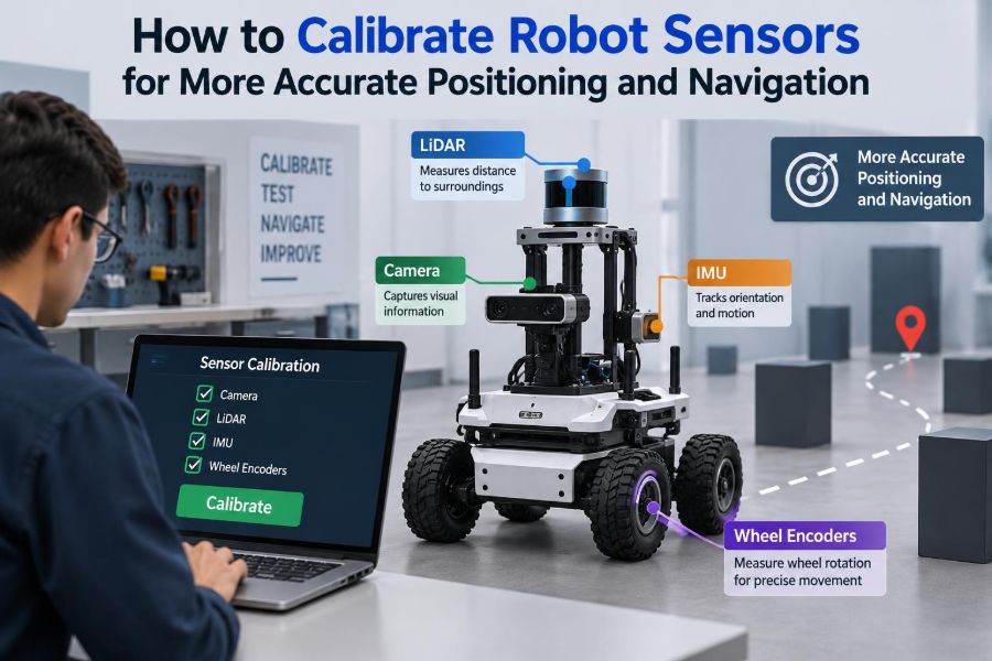

A mobile robot can drive flawlessly across an empty lab floor, then miss a docking station by a few centimeters after a week on the job. A robotic arm can repeat the same programmed motion while slowly placing parts off-center. In both cases, the software may be doing exactly what it was told.
The problem is often that the robot’s measurements no longer match the physical world. Wheels wear, cameras move slightly, temperature changes electronics, and a sensor mounted by hand is rarely positioned exactly where its CAD model says it is.
Calibration is the disciplined process of measuring those differences and incorporating them into the robot’s model. It turns raw sensor readings into estimates that are useful for control, positioning, mapping, and navigation.
Good calibration is not a one-time ritual performed before deployment. It is a practical engineering loop: define what must be accurate, collect trustworthy data, estimate the right parameters, validate the result, and monitor for drift.
🧭 What Sensor Calibration Actually Means
Sensor calibration establishes the relationship between a sensor’s output and the physical quantity it is intended to measure. For a wheel encoder, that may mean converting pulse counts into traveled distance. For an IMU, it means correcting acceleration and angular-rate readings for offset, scale, and axis misalignment.
In robotics, calibration also includes geometric calibration: determining where sensors sit and how they are oriented relative to the robot body. A camera can be internally accurate yet still lead navigation astray if its pose on the chassis is wrong.
🎯 Accuracy, Precision, and Repeatability
These terms are related but not interchangeable. Accuracy describes closeness to the real value; precision describes how tightly repeated measurements cluster; repeatability describes whether a robot can reproduce a result under the same conditions.
A range sensor that consistently reports a wall 3 cm too far away is precise but inaccurate. A noisy sensor may be accurate on average but unsuitable for tight control. Calibration usually improves systematic error; filtering and better hardware address much of random noise.
🧩 Build a Measurement Model First
Do not begin by collecting data without deciding what the data should identify. Write a measurement model that describes how the robot state and unknown parameters produce a sensor reading.
For example, a differential-drive odometry model may include left and right wheel radii, wheelbase, and encoder scale. A camera model may include focal length, image center, lens distortion, and camera-to-robot transform. The model need not capture every physical detail, but it must capture errors large enough to matter.
📏 Define Requirements Before Tuning
Calibration targets should come from the task. A warehouse robot that must enter a charging dock needs dependable local alignment. A lawn robot may tolerate larger global position error if it can maintain safe boundaries.
- Specify the operating area, surfaces, lighting, speeds, and temperatures.
- State whether the requirement concerns absolute position, relative motion, heading, or obstacle distance.
- Choose a reference method more accurate than the performance you intend to verify.
- Set acceptable error thresholds for normal operation and for safety-critical behavior.
Without this context, it is easy to spend time improving a parameter that has little effect on the robot’s actual mission.
🧱 Establish Coordinate Frames
Every positioning system needs a consistent language for location and orientation. Common frames include world or map, robot base, odometry, camera, lidar, IMU, and individual wheel frames.
A transform states the position and rotation from one frame to another. Ambiguous frame names, reversed transforms, and mixed angle conventions can create errors that look like failed calibration. Document axis directions, units, rotation order, and transform notation before debugging numerical results.
🔗 Understand Extrinsic and Intrinsic Parameters
Intrinsic parameters describe a sensor itself. A camera’s focal lengths and distortion coefficients are intrinsic; an IMU’s bias and scale factors are intrinsic.
Extrinsic parameters describe the sensor’s placement relative to another frame. The translation and rotation between a lidar and the robot base are extrinsic. Both classes matter: a well-calibrated camera placed at the wrong angle produces consistently misleading geometry.
⚙️ Start With Mechanical Integrity
Software cannot permanently compensate for a loose bracket, bent encoder mount, slipping wheel hub, or vibrating camera mast. Inspect hardware before running a calibration routine, and repeat the inspection after any collision, repair, or payload change.
Tighten mounts to the appropriate specification, protect cable routing, and check that sensors have an unobstructed field of view. If a mount can flex under acceleration, a calibration performed while stationary may not represent the robot while moving.
🛞 Calibrate Wheel Encoders and Odometry
Encoders measure wheel or motor rotation, not ground travel. Converting counts to motion requires an effective wheel radius, gear ratio, encoder resolution, and drivetrain assumptions. The word effective matters: tire compression and contact conditions make it different from a nominal catalog radius.
Drive a measured straight path repeatedly in both directions and compare encoder-based distance with a reliable reference. Then command turns and compare heading change. For a differential-drive robot, unequal effective wheel radii cause curved “straight” paths, while an incorrect wheelbase mainly corrupts turning estimates.
🌧️ Account for Wheel Slip and Surface Changes
Odometry calibration does not eliminate slip. Smooth floors, dust, carpet transitions, ramps, hard acceleration, and carrying a new payload can all change traction and wheel deformation.
Treat wheel odometry as a useful short-term motion estimate, not unquestioned ground truth. If the robot operates across varied surfaces, validate the model on representative routes and allow localization software to rely more heavily on independent observations when slip is likely.
🌀 Remove IMU Bias Before Motion Tests
An inertial measurement unit, or IMU, commonly combines gyroscopes and accelerometers. A gyroscope bias is a nonzero angular-rate reading while the device is still; integrating that tiny error produces growing heading drift.
Keep the robot stationary during startup if the IMU estimates an initial bias. Record a static interval and inspect mean readings and noise. Bias can change with temperature and time, so robust navigation systems continue estimating it rather than assuming one startup measurement remains perfect forever.
🧊 Check IMU Scale, Alignment, and Gravity
Accelerometer readings should reflect gravity when the robot is static, with direction determined by orientation. Rotating the robot through known orientations can reveal scale error, axis non-orthogonality, and cross-axis sensitivity.
Verify that the IMU frame is correctly rotated into the robot-base frame. A 90-degree mounting mistake can make a filter interpret forward acceleration as lateral motion. Be especially careful with sign conventions: different software stacks may define positive rotation differently.
🧲 Calibrate Magnetometers With Caution
A magnetometer can provide a heading reference, but it senses the combined magnetic environment around the robot, not a perfect compass direction. Motors, batteries, steel frames, wiring currents, and nearby infrastructure can distort its field.
Collect samples across many orientations to estimate hard-iron offsets and soft-iron distortion. Then test heading in the actual installed location, with motors and payloads active. If the field changes sharply during operation, rejecting magnetometer updates may be safer than forcing the navigation filter to accept them.
📷 Calibrate Camera Intrinsics
Camera calibration estimates the mapping from three-dimensional rays to image pixels. Focal length, principal point, and lens distortion determine that mapping. Wide-angle lenses particularly need distortion modeling because straight physical lines can curve near image edges.
Use a known flat target, such as a checkerboard or coded calibration board, at varied distances, tilts, and image locations. Images concentrated in the center or taken from nearly identical poses cannot constrain distortion as well as diverse views can.
🧿 Validate Image Quality Before Blaming Math
Blur, low exposure, rolling-shutter effects, and poor target detection can contaminate camera calibration data. Reject images where corners are uncertain, the target is clipped, or lighting creates glare.
For robots that navigate while moving, inspect images under realistic motion and illumination. A calibration captured under ideal indoor light may be geometrically valid, yet visual localization can still struggle outdoors because the images lack stable, usable features.
🔦 Calibrate Lidar Placement and Range Behavior
A lidar often reports range reliably within its intended operating conditions, but its pose relative to the robot must still be known. A slight yaw error means map features appear rotated; a translation error can produce apparent position shifts during turns.
Check observations of flat walls, corners, and repeatable landmarks from several robot poses. Some range sensors also have limits with glass, dark absorbent materials, rain, fog, or highly reflective surfaces. Those are sensing limitations, not necessarily calibration failures.
📡 Treat Ultrasonic and Infrared Sensors as Local Sensors
Short-range ultrasonic and infrared sensors are valuable for obstacle detection and docking, but their readings depend strongly on target material and angle. Ultrasonic waves can reflect away from angled surfaces, while infrared measurements can be affected by surface reflectivity and ambient light.
Calibrate within the distances and target types the robot will actually encounter. Use conservative safety margins rather than assuming a single distance curve applies equally to fabric, glass, matte plastic, and angled metal.
⏱️ Synchronize Sensor Clocks
Even perfectly calibrated sensors can disagree if their readings refer to different moments. A camera frame captured before a turn but paired with an IMU pose after the turn creates a false geometric mismatch.
Hardware timestamps and synchronized clocks are preferable where available. Otherwise, measure communication and processing delays, then align streams as carefully as the platform allows. Time offset becomes more damaging as robot speed, turn rate, and sensor update interval increase.
🧠 Estimate Sensor-to-Sensor Transforms
Multi-sensor robots need accurate transforms between devices: camera-to-IMU, lidar-to-camera, lidar-to-base, and more. This is commonly called extrinsic calibration.
A practical approach is to create motion or target observations visible to both sensors, then solve for the transform that best explains them. The data must excite enough motion: if the robot only drives straight, some rotation and translation parameters may remain weakly observable.
🧮 Use Least Squares, but Inspect Residuals
Many calibration tools fit parameters by minimizing residuals: the differences between predicted and observed measurements. Least-squares fitting is useful, but a low average residual alone does not prove that the result will generalize.
Plot residuals by image location, range, angle, time, and motion direction. Patterns reveal model problems. For example, errors growing near camera edges suggest distortion issues; errors that grow after motor startup may point to vibration, electromagnetic interference, or temperature effects.
🧪 Separate Calibration Data From Test Data
Assess a calibration with data that was not used to compute it. Otherwise, an overfit model can appear excellent simply because it memorized quirks in the calibration set.
For a mobile robot, use a fresh route containing straight runs, turns, different headings, and typical speeds. Compare estimated pose to a trusted reference when possible, but also examine task-level outcomes: docking alignment, map consistency, and repeatability at workstations.
🗺️ Calibrate the Localization Pipeline, Not Just Devices
Positioning usually comes from sensor fusion rather than one sensor alone. An estimator such as an extended Kalman filter combines predictions from wheel and IMU motion with corrections from lidar, vision, GPS, beacons, or map matches.
Sensor calibration and filter tuning are different jobs. Correct measurement models should come first; only then tune uncertainty values so the filter neither trusts a noisy source too much nor ignores useful corrections. Inflating uncertainty can hide a problem, but it does not fix a bad transform.
📍 Use Ground Truth That Fits the Job
Calibration needs a reference. Depending on the accuracy and workspace required, that may be a tape-measured path, surveyed markers, a motion-capture system, a calibrated external camera, or carefully placed fiducial targets.
Every reference has uncertainty. A hand-measured line is often sufficient for wheel-scale checks but not for diagnosing millimeter-level arm positioning. Record how the reference was created, because unexplained disagreement may originate in the “ground truth,” not the robot.
🏭 Calibrate Across Real Operating Conditions
Bench results are a starting point, not deployment evidence. Test with normal payload, battery state, speed, floor condition, lighting, and network load. A camera transform may shift when a loaded suspension compresses; encoder behavior can change when tires warm or wear.
Where conditions vary widely, consider calibration parameters that are temperature-aware or operating-mode-aware. Use such complexity only when data demonstrates a stable relationship; adding parameters without observability can make estimates less reliable.
🧰 Create a Repeatable Calibration Procedure
A good procedure reduces dependence on the individual performing it. Define setup dimensions, warm-up requirements, target placement, motion sequence, data file naming, acceptance checks, and the location where resulting parameters are stored.
- Inspect mounting, connectors, wheels, and sensor windows.
- Warm up devices if their behavior changes after power-on.
- Collect data using a documented sequence and environment.
- Estimate parameters and save the raw data with the result.
- Run independent validation before releasing the robot.
This traceability makes it much easier to investigate a later regression.
🗃️ Version Parameters Like Software
Calibration files are part of the robot’s configuration, not disposable output. Version them alongside software and associate each set with robot serial number, sensor serial number, firmware version, mounting configuration, date, and validation outcome.
Never silently copy parameters from one robot to another unless the manufacturing process and verification plan justify it. Nominally identical units can differ enough in assembly, wheel geometry, or sensor placement to affect demanding tasks.
⚠️ Avoid Common Calibration Mistakes
- Calibrating only one condition: a perfect result at one speed or surface may fail elsewhere.
- Using bad data: outliers, blurred images, target-detection errors, and slipping wheels bias estimates.
- Changing several things at once: this makes the source of improvement or regression unclear.
- Confusing units: degrees versus radians and millimeters versus meters can cause dramatic errors.
- Ignoring observability: parameters cannot be estimated well when the collected motion does not reveal them.
When results seem implausible, first verify frames, timestamps, units, and physical mounting before reaching for a more complicated optimizer.
📈 Monitor Drift After Deployment
Calibration can degrade gradually. Wheel tread wears, mounts loosen, optics collect dust, and sensor electronics age. Monitor residuals, localization corrections, docking success, map alignment, and the frequency of estimator warnings.
A sudden change may indicate damage or a configuration error; a slow trend may signal normal wear. Define practical triggers for inspection or recalibration, especially after maintenance, transport, impacts, wheel replacement, or sensor remounting.
🛡️ Design for Safe Degradation
No calibration makes every sensor trustworthy in every environment. Navigation software should recognize implausible readings, use consistency checks between sensors, and transition to a safer behavior when localization confidence drops.
That behavior might be slowing down, stopping, requesting assistance, or using a more conservative obstacle margin. For robots operating near people or valuable equipment, calibration supports safety but does not replace a complete safety design and hazard analysis.
🔄 Know When Recalibration Is Necessary
Recalibrate after changes that alter geometry or measurement behavior: replacing wheels, moving a camera, changing a lidar bracket, updating sensor firmware that affects timing, repairing a drivetrain, or adding a payload that changes chassis attitude.
Also investigate recalibration when repeated validation shows systematic error. Do not recalibrate merely to mask intermittent failures; unstable power, packet loss, faulty encoders, or mechanical play require root-cause repair first.
✅ The Core Principle: Measure, Model, Verify
Reliable robot positioning comes from matching three things: the physical robot, the mathematical model, and the operating environment. Calibration provides the connection, while independent validation tests whether that connection holds beyond the controlled setup.
The most effective teams make calibration measurable and repeatable. They start with solid mechanics and clear coordinate frames, estimate only meaningful parameters, synchronize data, validate on fresh scenarios, and continue watching performance after deployment.
Calibrate sensors not to produce impressive numbers in a test, but to give the robot measurements it can trust when real motion, real surfaces, and real uncertainty arrive. 🦾🧭📍