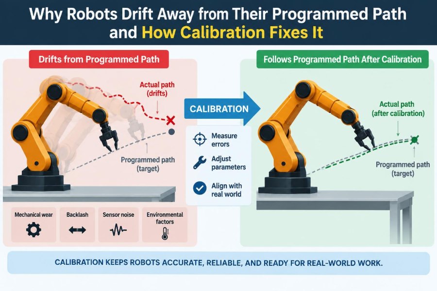

A mobile robot leaves its charging dock, follows a route across a warehouse, and arrives a few centimeters beside its target. A robotic arm repeats a pick-and-place cycle but gradually misses the center of a tray. The program may be exactly the same, yet the physical motion is not.
This gap between commanded motion and real motion is commonly called drift. It can waste time in a classroom project, reduce throughput on a production line, or create a safety concern when a machine works near people and equipment.
Drift is not usually a sign that robots are unpredictable or that programming has failed. It is a reminder that every robot operates through real motors, sensors, joints, wheels, surfaces, cables, temperatures, and measurements—all of which have limits.
Calibration connects the robot’s mathematical model to its actual body and workspace. Understanding that connection makes troubleshooting faster and helps engineers decide whether the answer is a software adjustment, a mechanical repair, a better sensor strategy, or a safer operating process.
🧭 What “Drifting from the Path” Actually Means
Path drift occurs when a robot’s actual position, orientation, or tool location differs from the planned one. The difference may appear continuously, such as a wheeled robot curving away from a straight line, or only after a sequence of moves.
For a mobile robot, drift may mean ending at the wrong map coordinate. For an industrial arm, it may mean its end effector—the gripper, welder, camera, or other tool mounted at the wrist—does not reach the programmed pose.
A robot can also appear to follow the path but still be wrong. Its chassis may reach a station while facing a few degrees off-angle, causing a pallet fork, camera, or gripper to misalign.
📍 The Difference Between Accuracy and Repeatability
Accuracy describes how close a robot gets to the intended target. Repeatability describes how consistently it returns to the same actual location when it repeats a command.
A robot may have good repeatability and poor absolute accuracy. For example, an arm might consistently place a part 3 mm to the left of a fixture. That is often easier to compensate for than a robot that lands in a different place every cycle.
| Behavior | Likely observation | Common interpretation |
|---|---|---|
| Poor accuracy, good repeatability | Same offset each cycle | Frame, tool, or model calibration error |
| Poor repeatability | Target varies from cycle to cycle | Backlash, slipping, noise, or unstable process |
| Error grows with distance | Near points are acceptable; far points miss | Scale, wheel radius, or kinematic parameter error |
| Error changes with direction | Approaching from opposite sides gives different results | Backlash, hysteresis, or compliance |
This distinction prevents a common mistake: trying to fix random variation with a single coordinate offset.
🧠 The Robot Follows a Model, Not Reality
Robot software calculates movement using a model: wheel diameters, gear ratios, joint lengths, encoder counts, camera geometry, and coordinate frames. The controller assumes these values represent the machine it controls.
Real machines depart from those assumptions. A wheel wears down, a joint flexes under load, or an encoder zero position shifts after service. Even small differences matter when calculations are chained through several axes or over a long travel distance.
Calibration estimates the parameters that make the model better match measured reality. It does not make the robot physically perfect; it makes commanded motion more truthful.
📐 Small Errors Accumulate into Large Misses
Many drift problems are cumulative. Consider a differential-drive robot that estimates distance from wheel encoder rotations. If its assumed wheel radius is slightly wrong, every calculated meter is slightly wrong too. Over a short route, the error may be hard to notice; over a long route, it becomes obvious.
Orientation errors compound as well. If a robot turns a little too far early in its path, it then travels forward in the wrong direction. The lateral error grows with distance even if its later straight-line motion is flawless.
This is why a robot that looks fine during a quick bench test can miss badly during an extended mission.
⚙️ Encoder Counts Are Measurements, Not Ground Truth
Encoders report motor or joint rotation. They are essential for feedback control, but they do not directly measure every motion that matters. A wheel encoder cannot tell whether a tire slipped on dust, and a motor encoder cannot always reveal flex between the motor and tool.
Incremental encoders count changes from a reference point. If the system loses counts because of electrical interference, poor wiring, or signal-processing faults, its estimated position can shift. Absolute encoders retain or report a unique position, but they still require correct installation and reference conventions.
When diagnosing drift, ask what the sensor measures physically—not just what value appears on a screen.
🛞 Unequal Wheels Bend Mobile Robot Paths
For a two-wheel differential-drive robot, equal commanded wheel speeds should produce a straight path. If one effective wheel diameter is larger, that wheel covers more ground per encoder count and the robot curves.
“Effective” matters because it includes more than the molded tire diameter. Tire compression, tread wear, wheel mounting, load distribution, and floor texture can all alter the distance traveled per rotation.
A practical test is to drive a long, measured straight course in both directions. A consistent curve that reverses direction with the robot often points toward wheel-scale mismatch or unequal drive behavior.
🧊 Wheel Slip Breaks Odometry
Odometry is position estimation based on motion sensors such as wheel encoders. It works well when the expected relationship between wheel rotation and ground travel holds. Slip breaks that relationship.
Acceleration, abrupt braking, ramps, loose debris, wet floors, cable drag, and turning in place can all create slip. A robot may believe it has turned 90 degrees while its chassis has rotated less, or it may believe it moved forward while its wheels briefly spun.
Calibration reduces systematic wheel-scale errors, but it cannot fully correct a one-time skid that was never observed by another sensor.
🧱 Floors and Payloads Change the Machine
A route calibrated on smooth concrete may not transfer cleanly to carpet, anti-slip mats, expansion joints, or uneven tile. Surface changes alter traction and rolling resistance, while a ramp shifts weight between wheels.
Payloads matter too. A delivery robot with an empty bin and the same robot carrying a heavy load may have different tire deformation and braking behavior. A robot arm carrying a heavier tool can sag slightly or excite vibration that was absent during teaching.
Calibration should therefore reflect the real operating configuration, including the tool, typical payload, and surface conditions where practical.
🔩 Backlash Creates Direction-Dependent Errors
Backlash is lost motion caused by clearance between mechanical parts, often gears, belts, lead screws, or couplings. When direction reverses, the motor can move briefly before the output mechanism fully takes up the clearance.
The result is a distinctive pattern: the same target is reached differently depending on the approach direction. An arm might be accurate when moving clockwise toward a fixture and offset when approaching counterclockwise.
Software compensation may help when backlash is stable and measured carefully. Excessive or changing backlash, however, is primarily a mechanical maintenance problem.
🦾 Flex and Compliance Move the Tool
Robot structures are not infinitely rigid. Links bend slightly, joints deflect under torque, and tool mounts can flex. This behavior is called compliance.
Compliance often appears only under load or at extended reaches, where leverage is greatest. A robot arm may calibrate well with an empty gripper yet miss when it lifts a part, presses a seal, or applies welding force.
Stiffer tooling, reduced acceleration, better support, payload-aware control, or force feedback may be more appropriate than simply changing target coordinates.
🌡️ Temperature Can Shift Position
Motors warm during operation, electronics drift slightly, lubricants change behavior, and structural materials expand or contract with temperature. In high-precision work, these changes can move a tool enough to matter.
Temperature effects are usually gradual, which can make them difficult to spot. A system may pass a morning acceptance check but show a consistent offset after hours of continuous production.
Warm-up routines, thermal monitoring, and calibration at representative operating conditions can reduce surprises. Not every robot requires thermal compensation, but it should be considered when errors track run time or ambient conditions.
🔌 Electrical Noise and Timing Problems Add Hidden Error
Signal noise, poor grounding, damaged cables, loose connectors, and electrical interference can corrupt sensor readings or interrupt communication. These issues may create intermittent drift that looks mechanical at first.
Timing also matters. A camera image, encoder reading, and robot pose must refer to the same moment. If a moving robot uses delayed vision data without accounting for latency, it acts on an outdated view of the scene.
Intermittent faults deserve evidence-based diagnosis: inspect logs, check signal integrity, reproduce the condition safely, and avoid assuming every position error is a calibration issue.
🦿 Joint Zeroing Sets the Arm’s Starting Truth
Most articulated arms need a known reference for each joint. Joint zeroing, homing, or mastering establishes where the controller considers that reference to be.
If one joint is zeroed incorrectly, every pose calculation downstream can be wrong. The visible error depends on arm configuration: a small angular offset near the base can create a substantial tool displacement at full reach.
After replacing a motor, encoder, reducer, or joint component, follow the manufacturer’s mastering procedure exactly. Guessing a zero mark may produce a robot that moves smoothly but is geometrically wrong.
🧮 Kinematic Parameters Define Robot Geometry
Kinematics describes the relationship between joint motion and tool motion. The kinematic model includes link lengths, joint-axis directions, offsets, and the order in which joints move.
Manufacturing tolerances, assembly variation, and service work mean nominal dimensions are not always sufficient for demanding tasks. Kinematic calibration uses measurements at known poses to estimate more realistic parameters.
This is different from shifting a single target point. A corrected kinematic model can improve accuracy across a workspace, while a local offset may only fix one location.
🧰 Tool Center Point Errors Follow Every Move
The tool center point, often called TCP, is the point on a tool that the robot controls—for example, a gripper fingertip, dispensing nozzle, or welding electrode tip. The controller must know its position and orientation relative to the wrist flange.
If the TCP is entered incorrectly, the robot may place the flange correctly while the functional end of the tool misses the work. Changing a gripper, replacing a worn nozzle, or rotating a camera mount can invalidate a previous TCP.
Multi-pose TCP procedures estimate the tool geometry by bringing the tool point to one fixed reference from several orientations. They are more reliable than measuring by eye when precision matters.
🗺️ Coordinate Frames Must Agree
Robots move through coordinate frames: base frame, tool frame, workpiece frame, camera frame, map frame, and sometimes conveyor frame. A frame defines an origin and axes used to describe position and orientation.
Many “drift” reports are actually frame errors. A fixture might have shifted, a map may be referenced to an old docking location, or a work object frame may be rotated slightly relative to the physical part.
Use clear naming and change control. A correct target in the wrong frame is still a wrong physical move.
📷 Camera Calibration Has Its Own Geometry
A vision-guided robot needs camera calibration to relate image pixels to rays and real-world coordinates. Lens distortion, focal properties, and the camera’s pose relative to the robot or workspace all matter.
For a fixed camera, the relationship between camera and robot base must be known. For a wrist-mounted camera, hand-eye calibration estimates the transform between camera and end effector.
A vision system can identify parts accurately in its image yet direct the robot inaccurately if that transform is wrong. Recalibrate after moving the camera, changing the lens, or altering a rigid mount.
🧭 Localization Corrects Mobile Robot Estimates
Because wheel odometry drifts, mobile robots often combine it with external observations. This process is called localization: estimating where the robot is by comparing sensor data with a map or known references.
Possible references include lidar scans of walls, camera-detected markers, fixed beacons, inertial sensors, or docking landmarks. Each sensor has failure modes, so practical systems often fuse more than one source.
Localization does not eliminate the need for good wheel calibration. It limits accumulated error by periodically correcting the estimate before small mistakes become large route deviations.
🧩 Sensor Fusion Needs Sensible Assumptions
Sensor fusion combines information from multiple sensors, weighting each according to expected uncertainty. For example, encoders may provide smooth short-term motion estimates, while lidar provides occasional strong corrections against a map.
Adding sensors is not automatically an upgrade. A poorly calibrated IMU, an incorrectly mounted camera, or a map that no longer matches the facility can inject misleading information.
The goal is not to collect maximum data. It is to build a consistent state estimate whose assumptions are tested in realistic operating conditions.
🎯 Calibration Is Measurement Plus Model Update
Calibration is sometimes treated as pressing a menu button or entering an offset. More broadly, it is a controlled process: measure a known reference, compare it with the robot’s reported result, estimate the source of discrepancy, and update relevant parameters.
A useful calibration has a defined purpose. Are you correcting a TCP, wheel radius, camera transform, joint zero, or work-cell frame? Without that question, a set of changed values may hide the symptom while making the system harder to maintain.
Just as importantly, calibration must be verified with independent test points rather than only the points used to fit the correction.
📏 Start with a Baseline Test
Before changing settings, create a repeatable baseline. Mark test locations, record robot-reported positions, measure actual positions with suitable tools, and note direction, speed, payload, temperature, and floor condition.
For a mobile robot, useful tests include straight travel, fixed-radius turns, and repeated docking. For an arm, test several poses across the workspace and approach the same feature from different joint configurations where possible.
Baseline data turns “it seems off” into a pattern that can be reasoned about.
🔍 Diagnose the Error Pattern Before Adjusting
Error shape is diagnostic. A constant offset across the workspace often suggests a frame or TCP issue. An error that grows with travel distance suggests scale error. An error that changes after reversals suggests backlash.
- Only one station fails: inspect fixture position, local frame, and station-specific hardware.
- All stations fail similarly: inspect base frame, tool frame, or robot mastering.
- Failures appear under load: investigate compliance, payload settings, and acceleration.
- Failures are sporadic: investigate slip, vision confidence, communication, and sensor noise.
This reasoning narrows the search and avoids compensating for a mechanical fault with misleading software values.
🧪 Calibrate One Variable Family at a Time
Changing wheel parameters, controller gains, map alignment, and camera settings in one session makes results difficult to interpret. If performance improves or degrades, no one can tell which change caused it.
Use a controlled sequence: inspect the mechanism, establish references, calibrate the most foundational geometry, then calibrate tools and sensors attached to that geometry. Record old and new values, the procedure used, and verification results.
This discipline matters especially in teams. A calibration that cannot be reproduced is only a temporary adjustment.
🛠️ A Practical Mobile Robot Calibration Workflow
A differential-drive platform provides a clear example. First confirm tire condition, secure hubs, drivetrain health, and representative load. A loose wheel or slipping gearbox should be repaired before software calibration begins.
- Measure a straight test route on the actual operating surface.
- Drive repeated runs at moderate speed and compare estimated versus actual distance.
- Adjust distance-per-count or effective wheel-radius parameters carefully.
- Run turn tests to estimate track width, the effective distance between wheel contact paths.
- Repeat straight and turn tests in both directions, then verify on an independent route.
For environments with varying traction, add localization checks or reference markers rather than expecting odometry calibration alone to solve every deviation.
🏭 A Practical Robot Arm Calibration Workflow
For an arm, begin with safety and mechanical condition: mounting bolts, tool attachment, cable routing, joint health, and correct payload data. Then verify joint mastering according to the robot’s documented procedure.
Calibrate the TCP with an appropriate reference point and multiple arm orientations. Next establish the work-object or fixture frame from accurately known features. If vision guides the task, calibrate the camera relationship and validate it with parts placed in several positions.
Finally, test production-like motions at the outer and inner regions of the workspace. A calibration performed only near the center may conceal reach-dependent error.
✅ Validate Beyond the Calibration Points
A model can fit the points used during calibration while performing poorly elsewhere. This is a form of overfitting: the correction describes the training measurements but does not generalize to the working area.
Validation should use separate points, normal speeds, intended payloads, and realistic approach directions. For critical processes, measure not only position but also orientation, since a small angular error can matter greatly at a long tool length.
Keep acceptance criteria tied to the task. A floor-cleaning robot and a precision dispensing cell do not require the same tolerance or verification method.
🚧 Safety Comes Before Accuracy Tuning
Calibration may require jogging a robot, moving close to fixtures, or using reference objects in the workspace. These activities can introduce pinch, crush, collision, electrical, or unexpected-motion hazards.
Use the required operating mode, speed limits, guards, emergency-stop procedures, and trained personnel for the specific platform. Never defeat safety functions merely to make calibration more convenient.
If a position error could cause a collision, establish conservative limits and clearance before testing. Better accuracy is valuable only when achieved without creating a new hazard.
🧼 Maintenance Preserves Calibration
Calibration is not a substitute for maintenance. Worn tires, loose fasteners, contaminated sensors, stretched belts, damaged cables, and deteriorating bearings can change a robot after it has been calibrated.
A sensible maintenance plan checks the components that define geometry and sensing. It also records events likely to invalidate calibration, such as collisions, tool changes, wheel replacement, camera remounting, or drivetrain service.
Trend data helps. A slowly growing correction or declining repeatability is often a signal to inspect the hardware before failure becomes disruptive.
📋 Common Calibration Mistakes to Avoid
One common mistake is calibrating around a fault. Entering a large offset may restore one target while masking a bent bracket, loose tool, or incorrect joint reference.
Other avoidable mistakes include:
- Calibrating with an unrepresentative payload or surface.
- Using only one measurement point for a workspace-wide claim.
- Skipping independent verification after parameter changes.
- Failing to document units, frame conventions, and parameter versions.
- Assuming a camera or sensor mount returned to exactly the same pose after service.
Careful records are not bureaucracy; they let the next technician distinguish a deliberate calibration from an unexplained setting.
🔄 Recalibration Should Follow Meaningful Changes
There is no universal recalibration interval because robot designs and task tolerances differ. A low-precision platform in a stable environment may need only periodic checks, while a tight-tolerance cell may require frequent verification.
Recalibrate or at least revalidate after events that change geometry, sensing, or operating conditions: a collision, replacement of wheels or tools, encoder service, fixture relocation, camera movement, major payload changes, or a new floor surface.
Also investigate when operators observe a new pattern. A drift report is useful information, not merely a nuisance to be corrected at the interface.
🧭 The Core Principle: Keep the Digital and Physical Robot Aligned
Robots drift when their internal estimate of motion no longer matches what their bodies and environments actually do. The cause may be systematic geometry error, changing mechanics, unobserved slip, uncertain sensing, or inconsistent coordinate frames.
Calibration addresses the systematic part by aligning parameters with measured reality. Feedback sensors and localization address disturbances that occur during operation. Maintenance protects the physical conditions that calibration assumes.
The strongest approach combines all three: a sound mechanical system, a measured model, and enough observation to detect when the real world has changed.
A robot stays on its intended path when its sensors, model, mechanics, and workspace references are treated as one connected system—not as separate problems to patch after a miss. That mindset turns drift from a mystery into a measurable engineering task. 🤖📏🧭