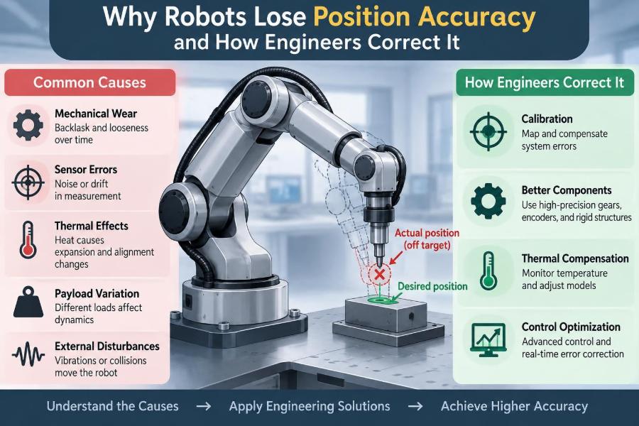

A robot can complete the same programmed move hundreds of times and still miss the intended point. The miss may be tiny: a weld begins slightly beside its seam, a gripper arrives a few millimeters off-center, or a camera sees a feature in the wrong place.
On a factory floor, those small offsets can become rejected parts, tool wear, slow cycle times, and difficult troubleshooting. In a laboratory or warehouse, they can mean failed experiments, misplaced bins, or a mobile robot that slowly drifts away from its map.
The confusing part is that a robot may look perfectly healthy. Its motors run, its encoder values change, and its software reports that it reached the commanded coordinates. Yet the physical world disagrees.
Understanding that gap is central to robotics engineering. Position accuracy is not one component specification; it is the result of mechanics, sensing, control, calibration, environment, and the way engineers define the task itself.
🎯 Position Accuracy Is Not the Same as Repeatability
Position accuracy describes how closely a robot reaches a commanded or known real-world location. Repeatability describes how closely it returns to the same location over repeated attempts.
A robot might consistently stop 2 mm away from a fixture. That robot has poor absolute accuracy but good repeatability. This distinction matters because a fixed error can often be calibrated out, while variable error is harder to predict and correct.
Industrial robot specifications commonly separate these ideas. Engineers should do the same in acceptance tests, because “it lands in the same place” does not necessarily mean “it lands in the right place.”
📍 The Coordinate Frame Problem
Every position command is expressed in a coordinate frame: joint coordinates, robot base coordinates, tool coordinates, workpiece coordinates, camera coordinates, or a map frame for a mobile robot. An error in any transformation between frames becomes an error at the task point.
Imagine telling someone to place a cup “10 cm to the right,” without agreeing on whose right or where the origin is. Robots face the precise mathematical version of that ambiguity.
Engineers use transformations to convert coordinates between frames. If the robot base frame is shifted, the tool center point is wrong, or the fixture frame is outdated, a mathematically correct motion can still produce a physically wrong result.
🦾 Kinematic Models Are Useful Approximations
A robot controller uses a kinematic model: a geometric description of links, joint axes, and link lengths. From joint angles, it predicts the end-effector pose, meaning its position and orientation.
Real robots never match this ideal model perfectly. A nominal 400 mm arm link may differ slightly from its drawing, a joint axis may not be perfectly orthogonal, and assembly tolerances can shift component locations.
For a small robot working over short distances, the difference may be acceptable. On a long-reach arm, small angular or dimensional deviations can create a noticeable tool-point error, especially near the edge of the workspace.
📐 Link-Length and Joint-Axis Errors Accumulate
Serial robot arms are chains of transformations. Each link and joint contributes to the final pose, so geometric errors can accumulate along the chain.
A slight error in an early shoulder joint matters more than a similar error near the wrist because it rotates all downstream links. This is similar to holding a long ruler: a tiny change in its angle at your hand creates a larger sideways displacement at the far end.
Geometric calibration identifies parameters such as link offsets, joint-axis directions, and joint zero locations. The corrected parameters can then be incorporated into the robot model or used as compensation in a higher-level control system.
⚙️ Encoder Resolution Is Only One Part of Measurement Quality
Encoders report motor or joint rotation, often as discrete counts. Their resolution limits the smallest rotation that can be directly distinguished, but high resolution alone does not guarantee accurate position.
An encoder can measure a motor shaft extremely finely while the mechanism between the motor and tool flexes, slips, or contains backlash. It may also have offset, scale, or alignment errors.
Think of a precise watch measuring how far you turn a screwdriver. It does not prove that the screw moved by the same amount if the screwdriver bit is loose. Good sensing must be paired with a mechanically faithful connection to the task point.
🔩 Backlash Creates Direction-Dependent Error
Backlash is lost motion caused by clearance between mating parts, such as gear teeth, lead screws and nuts, or worn transmission elements. When motion reverses, the actuator may move before the load responds.
The practical symptom is a direction-dependent position. A robot can approach the same point from the left and from the right and stop at slightly different locations.
Engineers can reduce backlash through preload, better gearboxes, direct-drive joints, and maintenance. Software compensation may help when backlash is stable and characterized, but it becomes unreliable if wear, load, or temperature changes the amount of lost motion.
🪢 Compliance Lets the Robot Bend Under Load
No real robot is infinitely stiff. Links bend, gearboxes twist, bearings deform, and mounting structures flex. This compliance means the tool pose depends partly on the forces and torques applied during motion or contact.
A gripper may be accurate while moving freely but shift when it presses a part into a fixture. A heavy welding torch can sag differently at different arm configurations. These are not necessarily controller faults; they are mechanical deflections.
Stiffness-focused design, lighter end effectors, shorter reaches, and force-aware processes reduce the problem. For precision contact work, engineers often model or measure deflection under representative loads rather than relying on unloaded tests.
🏗️ The Robot Base Is Part of the Robot
Calibration cannot rescue a robot that is mounted on a weak, moving, or poorly characterized foundation. A pedestal can deflect, a mobile platform can settle on uneven flooring, and a machine frame can vibrate when nearby equipment runs.
Even a rigid base can be installed with an unintended orientation relative to the cell. If the base pose is not measured correctly, all base-frame commands inherit that error.
Practical checks include verifying anchor integrity, evaluating structural stiffness, and measuring robot position while the expected process loads are present. The most accurate arm in the cell cannot overcome a shifting reference underneath it.
🌡️ Temperature Changes Geometry
Materials expand and contract with temperature. Motors, gearboxes, links, fixtures, rails, and surrounding structures do not necessarily warm at the same rate or by the same amount.
A robot calibrated after a cold startup may behave differently after hours of high-speed operation. Heat from motors can alter joint behavior, while a warm production area can change the relative geometry between robot and workpiece.
Engineers manage thermal effects by allowing warm-up when appropriate, locating sensitive measurements away from heat sources, monitoring temperature, and calibrating under conditions that resemble production. Thermal compensation is useful only when its temperature-position relationship has been measured and remains stable.
🧲 Friction and Stiction Distort Small Motions
Friction resists motion, while stiction is the extra resistance that must be overcome to begin moving. At very low speeds or during tiny corrections, stiction can make a joint hesitate and then jump.
This can produce stick-slip motion, poor contour following, or inconsistent settling near a target. Lubrication condition, seal drag, cable routing, and wear all influence the behavior.
Control engineers may use friction compensation, but the model must be treated cautiously: friction changes with temperature, speed, load, and time. Mechanical health and suitable operating conditions remain as important as clever control algorithms.
🔌 Servo Control Has Following Error
A motion controller commands a target trajectory, but motors and mechanics require time and torque to follow it. The difference between commanded and actual motion is called following error.
During rapid acceleration, a heavy arm may lag behind the ideal path. If gains are too low, the response is sluggish. If gains are too aggressive, vibration or oscillation can appear, worsening final accuracy.
Well-tuned servo loops balance response speed, stability, noise sensitivity, and mechanical limits. The best tuning depends on payload, posture, tool, and process, which is why a controller tuned for an empty gripper may not perform equally well with a heavy payload.
🏃 Fast Moves Can Trade Accuracy for Throughput
High speed and acceleration increase inertial forces. Those forces can excite structural vibration, amplify compliance, and make it harder for the controller to settle precisely at the endpoint.
A pick-and-place system may arrive near the target quickly but need extra time for vibrations to decay. If the next operation begins too soon, the apparent position error becomes a process error.
The solution is not automatically to slow every move. Engineers can optimize path shape, reduce abrupt jerk, improve structural stiffness, tune the servo system, or reserve slower precision moves for the final approach. Throughput and precision should be evaluated together.
📦 Payload Changes the Dynamics
Payload mass, center of gravity, and rotational inertia strongly affect robot behavior. A tool mounted farther from the flange creates more torque than the same mass located close to the wrist.
If the controller uses inaccurate payload data, gravity compensation and dynamic feedforward may be wrong. The arm can droop, overshoot, or track differently across orientations.
Before demanding high accuracy, engineers should enter verified payload properties and test the actual end-effector configuration, including cables, hoses, adapters, fasteners, and product mass. “Tool only” data is often not enough.
🧰 Tool Center Point Errors Move Every Task
The tool center point, or TCP, is the point on the end effector that the robot treats as its working tip. It might be the center of a gripper, a drill tip, a dispensing nozzle, or the focal point of a sensor.
If the TCP definition is wrong by a few millimeters, every programmed location is wrong by a related amount. A mistaken tool orientation can be especially damaging because it creates position error that varies with wrist angle.
Engineers calibrate the TCP using physical reference methods, measurement systems, or vendor-supported routines. After a collision, tool change, or replacement of a bent adapter, TCP verification should be part of recommissioning.
🧭 Workpiece Frames Drift Too
Programmers frequently assume that the part fixture is exactly where it was during teaching. Production reality often disagrees: a fixture is adjusted, a pallet seats differently, a part varies, or a new batch arrives with a shifted datum.
This is a workpiece-frame problem, not necessarily a robot-arm problem. The robot may reach its programmed coordinates accurately while the object has moved.
Locating pins, repeatable pallets, fiducial marks, probing routines, and machine vision can establish the actual part pose. The right approach depends on the part variation, cycle time, and consequence of a missed operation.
👁️ Vision Adds Measurement Power—and New Errors
Vision guidance can correct for changing part location and orientation, but a camera does not simply “see coordinates.” It estimates them through optics, image processing, camera calibration, and transformations to the robot frame.
Lens distortion, poor lighting, glare, ambiguous features, motion blur, and a shifted camera mount can all degrade the estimate. A camera-to-robot calibration, often called hand-eye calibration when the camera moves with the robot, must remain valid.
Vision is highly valuable when parts vary or arrive randomly. It is less effective when the scene is poorly controlled or when the system has no robust way to detect low-confidence measurements.
📡 External Sensors Close the Loop
Joint encoders tell a robot what its joints did; external sensors can tell it what happened in the workspace. Examples include laser trackers, external cameras, linear scales, force-torque sensors, tactile sensors, and probing devices.
This distinction supports closed-loop correction. Rather than assuming the model is right, the system measures an error and adjusts the action.
External feedback adds cost, integration complexity, latency, and its own calibration requirements. Still, for tasks such as precision assembly, inspection, or docking, measuring the relevant physical quantity can be more reliable than trying to predict every source of error from the robot alone.
🗺️ Mobile Robots Face Localization Drift
For a mobile robot, position accuracy includes its estimate of where it is in a building or outdoor environment. Wheel encoders accumulate error when wheels slip, tires compress, or the floor is uneven.
Inertial sensors can bridge brief gaps but also drift over time. Localization systems therefore combine measurements from cameras, lidar, landmarks, global navigation signals where available, and wheel odometry.
A warehouse robot that believes it is 10 cm from a rack when it is actually 20 cm away may fail a docking task even if its arm and local sensors are functioning correctly. Map accuracy and localization accuracy must be considered separately.
🧭 Orientation Error Can Become Position Error
Robotic pose has two parts: position and orientation. Engineers sometimes focus on where the tool tip is while overlooking its angle.
For a long screwdriver, dispensing needle, or inspection probe, a small orientation error moves the active point away from the intended line or surface. The effect grows with distance from the wrist or reference point.
Orientation also affects contact conditions. A slightly tilted gripper can push a part sideways; a tilted nozzle changes bead placement; a tilted camera changes perspective. Precision tasks need pose requirements, not only Cartesian position tolerances.
🧪 Accuracy Must Be Measured at the Task Point
A robot’s controller display is not a complete accuracy test. It reports internal estimates, which may be consistent with encoder readings but not with the external world.
Meaningful validation measures the actual process point using an appropriate reference: a calibrated artifact, dial indicator, probe, vision metrology setup, laser-based system, or part-quality measurement. The method must be accurate enough for the tolerance being assessed.
Test the poses, loads, speeds, directions, and temperatures that matter in production. A single test at the center of the workspace with no payload says little about performance at a difficult corner of the real task.
📊 Separate Bias, Scatter, and Time Variation
Good troubleshooting begins by classifying the error. A constant offset suggests calibration or frame error. Direction-dependent error suggests backlash or hysteresis. A load-dependent error suggests compliance or payload modeling. A warming trend suggests thermal effects.
Random-looking scatter may come from sensor noise, vibration, inconsistent part seating, or unstable control. A slow drift can indicate wear, shifting fixtures, or changing environmental conditions.
| Observed pattern | Likely contributors | Useful first check |
|---|---|---|
| Same offset at many points | Base, TCP, or workpiece-frame error | Verify coordinate calibrations |
| Different result by approach direction | Backlash, friction, hysteresis | Run bidirectional repeat tests |
| Error grows with reach or load | Compliance, payload data, structural deflection | Compare unloaded and loaded poses |
| Error changes over a shift | Temperature, wear, fixture movement | Log time and environmental conditions |
🔍 Use a Structured Troubleshooting Sequence
Changing controller gains before confirming the reference frames often wastes time. A disciplined sequence narrows the cause with fewer adjustments.
- Define the failing task point and the allowable error.
- Confirm that the measurement method and reference artifact are trustworthy.
- Check the tool, workpiece, base, and sensor coordinate frames.
- Compare results across approach directions, payloads, speeds, and temperatures.
- Inspect mechanics for looseness, wear, collisions, cable forces, and fixture movement.
- Only then tune controls or introduce compensation based on observed evidence.
This process prevents an engineer from masking a mechanical fault with software that works only under one narrow condition.
🧮 Calibration Corrects Systematic Error
Calibration estimates model parameters or coordinate relationships from measurements. Its purpose is to reduce systematic error: a consistent, explainable mismatch between the model and physical system.
Examples include identifying an accurate TCP, registering a camera to a robot base, refining kinematic parameters, or establishing the pose of a fixture. Calibration is most effective when the source of error is stable enough to measure and reuse.
It cannot eliminate random vibration, a loose mounting bolt, or a part that enters the cell in an unpredictable pose. Calibration should therefore be viewed as one layer of accuracy engineering, not a universal repair.
🛠️ Compensation Should Follow Physics
Software compensation can offset known geometric error, account for gravity-related deflection, or adjust a target based on a vision measurement. It is powerful when based on a real, repeatable relationship.
A risky approach is adding arbitrary offsets until a single test passes. That “fix” may fail at another location, with a different payload, or after the machine warms up.
Before applying compensation, ask what variable drives the error and whether it can be measured. If error changes with load, use load as an input. If it changes with temperature, validate a temperature-dependent model. If no stable pattern exists, improve the physical system instead.
🧱 Better Mechanical Design Prevents Error Early
Accuracy is easier to preserve than to recover. Early design choices determine how much correction will be needed later.
- Use stiff structures and minimize unnecessary reach.
- Place heavy masses close to supporting joints.
- Select transmissions with suitable backlash and torque capacity.
- Route cables and hoses so they do not pull unpredictably on the arm.
- Design fixtures with clear datums and repeatable seating.
- Provide access for calibration checks and maintenance.
These choices may increase upfront complexity, but they reduce dependence on fragile software workarounds and repeated manual teaching.
🧑🏭 Process Design Can Relax the Accuracy Requirement
Not every task needs the robot itself to provide final precision. Well-designed processes use guides, chamfers, compliant mechanisms, funnels, locating features, and force feedback to make assembly more tolerant.
For example, a hypothetical connector-insertion cell might use a tapered lead-in and force sensing rather than demand sub-millimeter open-loop placement from the arm. The robot gets close; the mechanical design handles the final alignment.
This is not lowering standards. It is assigning precision to the most reliable part of the system. Passive features are often fast, robust, and easier to validate than attempting to correct every variation through motion control alone.
⚠️ Common Accuracy Fixes That Fail
Several tempting practices create short-lived success. Re-teaching points without finding the cause can hide a drifting base or incorrect TCP. Increasing servo gains can excite resonance. Adding vision without controlling lighting can replace one error source with another.
Another mistake is using one “golden part” for all validation. A cell may perform well on that part while failing on normal manufacturing variation.
Engineers should also avoid treating vendor specifications as a guarantee of cell-level performance. Specifications are meaningful, but the installed robot, tool, fixture, payload, environment, and process create the accuracy that the application actually experiences.
📈 Monitor Accuracy as a Maintenance Signal
Position behavior changes over a machine’s life. Gear wear, bearing wear, collision damage, loose fasteners, degraded lubrication, and shifting fixtures may first appear as subtle deviations in process results.
Trend checks can identify this change before it becomes a major failure. Useful signals include reference-point checks, vision residuals, force signatures, cycle-time changes, and quality measurements tied to robot operations.
Monitoring should have meaningful limits and a defined response. Collecting data without knowing when to inspect, recalibrate, or stop the process does not improve reliability.
🧠 Build an Error Budget for the Whole Cell
An error budget lists the contributors that affect the final task tolerance: robot repeatability, calibration uncertainty, fixture variation, tool wear, sensing uncertainty, thermal movement, and process variation.
The contributions do not always combine as simple worst-case addition because some are correlated, directional, or random. Still, the exercise reveals where engineering effort will have the greatest effect.
If a fixture varies more than the robot, improving robot calibration may offer little practical benefit. If a vision system already localizes parts accurately, investing in a more accurate arm may not be the best next step. Measure the dominant contributor first.
🤝 Accuracy Is a System Property
Robots lose position accuracy because their internal model is never the whole physical world. Geometry differs from nominal dimensions, mechanics deform and wear, sensors have limits, controls must manage real dynamics, and external references move.
Engineers correct errors by first identifying their pattern, then choosing the right layer of response: mechanical improvement, calibration, sensing, feedback control, process design, or maintenance. The right answer depends on whether the error is fixed, variable, load-dependent, thermal, directional, or caused by the workpiece.
The central principle is simple: measure accuracy where the work happens, not merely where the controller believes the robot is.
Reliable robotic precision comes from aligning the model, the mechanism, the sensors, and the process around the real task point—not from trusting any one of them in isolation. 🎯🦾📍