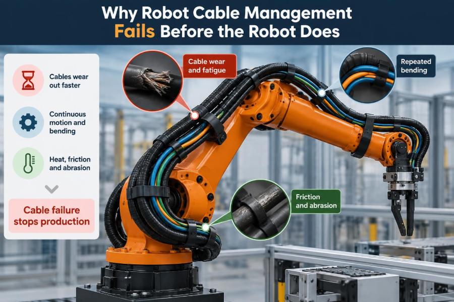

A robot cell may look healthy at the start of a shift. Axes home correctly, safety devices reset, and the end effector completes its first cycles without complaint.
Then a fault appears that seems unrelated: an intermittent sensor signal, a communication dropout, a tool that stops at one corner of its path, or a protective stop with no obvious mechanical cause. The robot is often blamed first.
But many of these failures begin in the moving wiring system. A cable can be electrically intact on a bench and still be near failure when it is repeatedly bent, twisted, pulled, rubbed, crushed, or exposed to process contamination.
For robotics engineers, cable management is not cosmetic finishing work. It is a moving mechanical subsystem that must survive the robot’s full motion envelope, production schedule, and maintenance reality. 🔧
🧠 1. Cable Management Is Part of the Robot Mechanism
Every cable attached to a moving robot becomes part of its mechanical design. It has mass, stiffness, bend limits, friction, and a preferred shape that can influence the arm as it moves.
When engineers treat routing as an afterthought, they often discover conflicts only after commissioning. By then, brackets are installed, cycle times are set, and changing the dress pack may require redesigning several interfaces.
The cable path must be designed with the same discipline as the end effector and robot mounting.
⚡ 2. Electrical Continuity Is Not Mechanical Reliability
A continuity test confirms that a conductor can carry a signal or power at that moment. It does not prove that the cable can survive thousands or millions of dynamic motion cycles.
Repeated flexing can fatigue conductor strands, damage shielding, deform insulation, and weaken terminations. A cable may fail only at a particular pose because that is where its damaged section is bent or tensioned.
This is why a fault can disappear during static troubleshooting and return as soon as automatic operation resumes.
🌀 3. Repeated Bending Creates Local Fatigue
Flexible cable is designed to bend, but it is not designed to bend indefinitely at any radius. When a cable is forced around a tight edge, the outer side stretches while the inner side compresses.
If that stress concentrates at one location on every cycle, conductor fatigue and insulation damage accumulate there. The visible jacket may remain intact long after the internal structure has begun to degrade.
- Use smooth, controlled bend paths.
- Prevent sharp bracket edges from defining the bend point.
- Keep repeated flexing away from connector backshells and cable entries.
📏 4. Bend Radius Is a Design Constraint, Not a Suggestion
The minimum bend radius supplied for a cable depends on its construction and intended service. A cable suitable for stationary routing may need a much larger radius than a cable built for continuous flexing.
Engineers should assess the radius under actual motion, not only when the robot is parked. A bundle that looks generous at home position may tighten significantly near a wrist singularity or extended reach pose.
Measure the smallest radius reached during operation, including during recovery and manual jog moves.
🔄 5. Twist Is Different From Bend
Bending curves a cable around an arc. Torsion twists the cable around its own length, and the two loads often occur together near robot wrists and rotating tools.
A cable can tolerate a reasonable bend path yet fail quickly if its ends are fixed while the middle is repeatedly twisted. Twist can also alter the position of individual conductors, shields, and fillers inside the jacket.
Watch for cables that coil, unwind, or develop a corkscrew shape. Those are mechanical warning signs, not merely untidy routing.
🤖 6. The Wrist Is Usually the Harshest Zone
The final robot joints combine high angular motion with limited space. They also carry tooling, adapters, pneumatic lines, and sensors, all of which compete for a safe route.
Wrist cabling may encounter rapid reversals, tool rotation, nearby fixtures, weld spatter, and the highest chance of accidental contact during teaching. A design that survives shoulder motion can still fail at the last axis.
Reserve space for controlled cable movement before finalizing the tool flange hardware.
🧰 7. A Dress Pack Must Fit the Entire Motion Envelope
A robot’s envelope is not just its programmed production path. It includes homing, jogging, calibration, error recovery, service positions, and potentially future programs.
Checking only a simulated nominal path can hide cable collisions or tension events. The bundle must be observed through all relevant joint combinations, especially full extension, folded positions, and axis reversals.
Clearance at one pose does not demonstrate clearance across the workspace.
🗺️ 8. Routing Needs a Planned Motion Map
A useful review identifies where cable length is consumed, where slack is stored, and where controlled bending happens. This turns vague visual inspection into a repeatable engineering assessment.
Key questions during a motion review
- Which joint creates the greatest cable displacement?
- Where does the bundle bend repeatedly?
- At which poses does slack disappear?
- Where could the bundle touch tooling, fixtures, or the robot body?
- Can the cable return naturally without snagging?
These questions are especially valuable when adding equipment to an existing cell.
📐 9. Too Little Slack Causes Tension Failures
A taut cable transfers motion directly into its conductors, jacket, connectors, and strain-relief points. The force may be small enough to avoid immediate damage but large enough to shorten service life.
Tension is often most severe at the end of a long reach or after an unexpected stop. It can pull on connectors, change sensor alignment, and make a cable bundle resist the robot’s intended motion.
Adequate slack allows movement, but it must be controlled rather than left loose.
🪢 10. Too Much Slack Creates a Different Set of Problems
Adding extra cable is a common reaction to tension concerns. Unmanaged slack, however, can droop into fixtures, catch on grippers, loop around robot geometry, or be pinched during motion.
Loose loops may also swing after fast acceleration and enter areas that appeared clear during slow manual jogging. In some processes, they collect debris or expose more surface to heat and contamination.
The target is not maximum slack. It is predictable slack with a defined place to move.
🧷 11. Clamps Must Support Without Crushing
Clamps are essential for keeping a bundle in its intended route, but an overtightened clamp can deform a cable jacket or restrict the natural redistribution of the bundle during flexing.
A clamp should hold the cable against unwanted movement without turning that location into a hard hinge. Hard clamp edges can create abrasion points, particularly when vibration causes tiny relative motions.
- Use clamp surfaces compatible with the jacket material.
- Avoid placing clamps at the main flex point.
- Inspect clamps after changes to cable diameter or bundle contents.
🛡️ 12. Strain Relief Protects the Most Vulnerable Ends
Connectors and cable entries are comparatively rigid. If bending or pulling reaches these points, the transition from flexible cable to rigid termination concentrates stress in a short distance.
Strain relief moves that stress away from the termination and gives the cable a controlled path into the connector or enclosure. It should accommodate real movement without allowing repeated tugging at the connector.
Good strain relief is particularly important for tool changers, cameras, force sensors, and compact wrist-mounted devices.
🧱 13. Abrasion Often Starts Small
Many cable failures start as harmless-looking rub marks. A bundle may graze a robot casting, a fixture corner, a fastener, or another hose once per cycle.
Over time, this contact can wear through the outer jacket and expose shielding or conductors. Abrasion is accelerated when grit, metal particles, or dried process residue becomes trapped between the cable and contact surface.
During inspection, look for polished spots, flattened jackets, discoloration, and debris patterns—not only obvious cuts.
🔥 14. Process Hazards Change the Cable Selection
Robot cells may expose cabling to heat, welding spatter, oils, coolants, washdown chemicals, ultraviolet light, dust, or sharp chips. A general-purpose cable may not tolerate the local environment even if it works mechanically.
Protection should match the actual hazard. A sleeve can help with abrasion but may trap heat or contamination; a conduit can protect against impact but may increase stiffness and reduce available bend radius.
Protective hardware solves one risk only if it does not create another.
📡 15. Signal Cables Have More Than One Failure Mode
Power cables may show obvious symptoms when a conductor breaks. Signal, encoder, network, and sensor cables can fail more subtly through intermittent connections, degraded shielding, or changes in impedance.
These issues may appear as random communication faults, unstable measurements, missed sensor states, or faults that occur only during motion. Replacing a device without checking its moving cable path can waste valuable troubleshooting time.
Separate mechanical damage analysis from electrical noise analysis, while recognizing that the same cable route can contribute to both.
⚙️ 16. Bundle Stiffness Can Affect Robot Performance
A large bundle resists bending and may behave like a spring attached to the arm. At high speed, that resistance can add load, disturb the tool path, or cause the bundle to whip after direction changes.
This is more noticeable with heavy hoses, protective conduits, and multiple cables bundled tightly together. The robot may still meet basic motion commands while the process result becomes less consistent.
Balance protection with flexibility, and avoid assuming that a thicker bundle is automatically more robust.
🏃 17. Fast Motion Reveals Problems Slow Jogging Hides
Teaching at low speed is necessary for safety, but slow motion does not reveal dynamic effects fully. Acceleration, deceleration, vibration, and inertia can shift a bundle into a different path than it takes during a gentle jog.
Commissioning should include observation at representative operating speeds where it is safe to do so. Watch the cable after the robot stops as well as during travel; delayed settling can indicate uncontrolled mass or stored twist.
A route that is quiet and stable at production speed is usually easier to maintain.
🧪 18. Simulate First, Then Validate Physically
Offline simulation can identify obvious clashes and help plan brackets, service loops, and external axis interfaces. It is valuable because routing decisions can be tested before hardware is difficult to change.
However, simulation models often simplify cable behavior. They may not represent real stiffness, gravity effects, sleeve friction, bundle expansion, or the way an installer naturally positions a cable.
Use simulation to reduce risk, then perform a physical sweep through the complete motion envelope.
🔍 19. Inspection Must Focus on Motion History
A static visual inspection should ask where the cable has been moving, not just what it looks like today. Damage frequently appears at repeated contact points, tight bends, and locations hidden behind covers.
Useful inspection clues
- Jacket whitening, flattening, cracking, or shiny rubbed areas.
- Loose clamps, shifted sleeves, or missing protective pieces.
- Bundles that no longer return to their normal resting position.
- Connector backshells under tension or with damaged strain relief.
- Recurring faults tied to a robot pose or axis movement.
Documenting the location helps distinguish progressive wear from a one-time incident.
🛠️ 20. Repairs Can Create New Weak Points
A quick splice or replacement section can restore production, but it may alter stiffness, diameter, shielding continuity, or the bundle’s natural flex behavior. The repaired point can become the next failure location.
After repair, review the route as if it were a new installation. Confirm that added sleeves, connectors, or junctions do not strike surrounding equipment or move into the main bending zone.
Temporary repairs deserve a follow-up plan; otherwise, “temporary” becomes the undocumented final design.
📦 21. Tool Changes Need Cable-Specific Review
A new gripper, welder, camera, or dispensing head changes more than payload. It can move the cable exit point, increase the required service loop, change wrist clearance, and introduce new media lines.
Even a small tool adapter can shift the bundle toward a fixture or reduce the available radius near the flange. Tool changes should trigger a cable routing review alongside payload and collision checks.
This matters most when the new tool adds rotation, vacuum, pneumatic, or high-current requirements.
🔀 22. External Axes Add Another Moving Interface
Track-mounted robots, positioners, elevators, and gantries create cable paths with longer travel and additional motion relationships. A cable may need to accommodate robot motion and external-axis travel simultaneously.
These systems often require guided carriers, festoon arrangements, or carefully designed service loops. The design must account for where the cable rests at both ends of travel and during combined motion.
Do not assess each axis separately when the cable experiences their motions together.
🧾 23. Documentation Prevents Repeat Mistakes
A maintainable cell should record cable part identifiers, routing photographs, clamp locations, protective components, and known inspection points. This gives technicians a reference when a bundle is removed or a tool is replaced.
It is also useful to record the intended orientation of connectors and the allowed path of any service loop. Without this information, well-meaning maintenance can reinstall a cable with hidden twist or insufficient slack.
The installed route is engineering information, not just assembly detail.
👷 24. Installation Quality Determines Service Life
Even a good drawing and correct cable selection can fail through poor installation. Common issues include twisting the bundle while tightening clamps, forcing a cable into place, leaving sharp tie ends, or routing around the nearest convenient bracket.
Installers need clear acceptance criteria: the cable should move freely through the intended path, avoid contact hazards, retain strain relief, and show no tension at extreme poses.
A final motion check should be a formal part of installation, not an informal glance before the cell is released.
📅 25. Preventive Maintenance Should Be Condition-Based
Calendar-based checks are useful, but cable wear depends heavily on motion count, process exposure, route severity, and unplanned events. A high-use wrist cable may need more attention than a stationary cabinet cable inspected on the same schedule.
Maintenance teams can improve decisions by tracking recurring fault locations, replacement history, visible wear, and changes in cycle conditions. That information identifies routes that need redesign rather than repeated replacement.
Inspect after collisions, crashes, tool changes, and any event that could pull or pinch the bundle.
🚨 26. Intermittent Faults Are Often Early Mechanical Warnings
An intermittent input, communication alarm, or brief power loss is easy to classify as a software or controller problem. Yet if the symptom follows a particular robot posture, moving cable damage should be high on the diagnostic list.
Test safely by comparing behavior across poses, observing the bundle during motion, and checking for tension or abnormal bending at the fault location. Avoid repeatedly flexing a suspected damaged cable unnecessarily, since this may worsen an internal break.
Finding the mechanical trigger early can prevent a minor fault from becoming a production-stopping failure.
✅ 27. The Core Principle: Control Motion, Do Not Merely Contain Cables
Reliable robot cable management comes from controlling where the bundle bends, twists, rests, and carries load. Cable protection, clamps, sleeves, and brackets are useful only when they support that controlled motion.
The strongest design considers the full system: cable construction, environment, robot kinematics, tool geometry, dynamic speed, maintenance access, and likely future changes. It is reviewed at realistic operating conditions and kept documented after commissioning.
A cable route succeeds when the cable can move exactly as intended—and nowhere it should not.
When robot cables are engineered as moving mechanical components, many “mysterious” robot faults become preventable maintenance issues instead of unexpected downtime. 🔧🤖⚡