
A warehouse robot slows as it approaches a pallet. A robotic arm must stop within millimeters of a fixture. A door opens when someone walks toward it, while a drone holds its altitude over uneven ground.
These systems may look very different, but each depends on a deceptively basic question: what is happening nearby, and how confidently can the machine measure it? The answer comes from sensors.
Choosing a sensor is not simply a matter of finding one with the longest range or the smallest advertised error. The right device depends on what must be measured, what the target is made of, how quickly the scene changes, and how harsh the environment is.
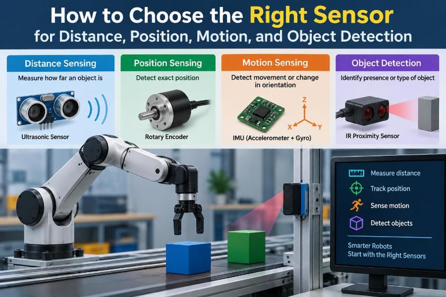
A useful sensor choice begins by separating four jobs that are often mixed together: measuring distance, measuring position, detecting motion, and deciding whether an object is present at all.
🧭 Start With the Measurement, Not the Part Number
Before comparing products, write a sentence describing the measurement the system needs. “Detect a box at the conveyor edge” is a different requirement from “measure the box’s distance continuously to within a few millimeters.”
Also distinguish the physical quantity from the control action. A robot may use a distance sensor to trigger braking, but the sensor requirement is still distance, range, update rate, and uncertainty—not “braking.”
- Distance: separation between sensor and target.
- Position: location along a path, angle, or coordinate system.
- Motion: change in position, speed, direction, vibration, or presence of movement.
- Object detection: a yes/no decision about an object or feature.
📏 Define What “Distance” Really Means
Distance can be a single straight-line range, clearance to the nearest obstacle, height above a floor, or the profile of a surface. A sensor that reports the nearest return may be unsuitable if a robot needs the distance specifically to a wall behind a railing.
State the usable minimum and maximum range. Many sensors cannot measure reliably too close to their face, and many lose signal, resolution, or repeatability near their published maximum range.
📍 Position Can Be Absolute or Relative
An absolute position measurement tells the system where it is after power-up, such as an encoder that reports a unique shaft angle. A relative position measurement reports movement from a known starting point, such as pulses counted from an incremental encoder.
Relative systems need a reference procedure: a home switch, limit stop, fiducial mark, or known mechanical datum. If power loss, missed counts, or slip matters, plan for how the machine will recover its reference.
🏃 Motion Is More Than Speed
Motion sensing may mean detecting that a person entered a room, measuring conveyor speed, identifying the direction of a rotating shaft, or observing vibration in a motor. These needs point to different sensor families.
A passive infrared sensor can notice changing thermal radiation from a moving person, but it does not precisely track their location. An encoder measures shaft rotation well, but cannot directly tell whether a person is standing in a doorway.
✅ Detection Is a Decision Problem
Object detection often sounds simple: object present or absent. In practice, the decision threshold must handle changes in object color, orientation, spacing, vibration, background surfaces, and contamination.
Ask what error is worse. A false positive may pause a conveyor unnecessarily; a false negative may allow a tool to close on an unseen part. That consequence should shape both sensor choice and safety architecture.
🎯 Separate Accuracy, Resolution, and Repeatability
Accuracy describes closeness to the true value. Resolution is the smallest reported change. Repeatability is how consistently the sensor returns the same result under the same conditions.
A device can have fine resolution yet be inaccurate because of offset, temperature drift, or target-dependent bias. In a pick-and-place system, repeatability may matter more than absolute accuracy if calibration removes a stable offset.
⏱️ Match Update Rate to the Moving Scene
A sensor must provide useful data before the robot has moved too far. At higher speeds, latency from sensing, filtering, communications, and control logic becomes a physical distance error.
For example, a slow tank-level measurement may tolerate long averaging. An obstacle sensor on a fast mobile robot needs a known, low-latency path from measurement to braking decision. Check update rate, response time, and whether the interface adds delays.
📐 Build a Measurement Budget
Do not assign all allowable error to the sensor. Mechanical mounting tolerance, target variation, electrical noise, calibration error, timing uncertainty, and software filtering all consume part of the budget.
If a gripper needs 5 mm of clearance, a sensor with 5 mm uncertainty is rarely enough by itself. The total uncertainty must leave margin for the machine, target, and operating conditions.
🔦 Understand Active and Passive Sensing
Active sensors emit energy and observe its return or interruption. Examples include ultrasonic, laser, radar, and inductive sensors. They can measure or detect without depending entirely on ambient conditions, but their emitted signal can interact with materials and neighboring sensors.
Passive sensors observe energy already present, such as a camera using ambient light or a passive infrared motion detector. They may consume little power, but performance can change strongly with lighting and scene temperature.
📡 Ultrasonic Sensors for Broad, Simple Ranging
Ultrasonic sensors send sound above the audible range and measure echo timing. They are commonly useful for moderate-range presence and distance tasks, especially when color or visible-light conditions would trouble an optical sensor.
They can struggle with soft fabrics, angled surfaces, narrow objects, air turbulence, temperature variation, and acoustic cross-talk. Their beam is often wider than a laser beam, so they may detect a nearby edge rather than the intended target.
🔴 Optical Time-of-Flight for Focused Distance
Optical time-of-flight sensors estimate distance from the travel time or phase behavior of emitted light. Their narrow field of view can help isolate a target, and they are useful in compact ranging systems.
Reflectivity, surface angle, strong sunlight, transparent materials, and multiple reflections can complicate readings. Treat maximum range as target-specific: a bright, cooperative target is not equivalent to a dark, angled rubber surface.
📷 Triangulation Sensors for Short-Range Precision
Laser triangulation projects light onto a target and observes where the reflected spot falls on a detector. As target distance changes, the observed geometry changes.
This approach can offer detailed short-range measurements, including surface profile. It is sensitive to the optical properties of the target, however, and specular metal, translucent plastic, or rapidly changing surface finish may require careful evaluation.
📻 Radar for Difficult Visibility Conditions
Radar uses radio-frequency energy and is often attractive where dust, fog, rain, or poor visible lighting make optical sensing difficult. It can also detect objects at longer ranges than many compact optical sensors.
Its trade-off is interpretation. Radar may see reflections from multiple structures, and its angular detail depends on antenna design and processing. It is often excellent for robust range and motion information, but not automatically the best choice for fine object boundaries.
🧲 Inductive Sensors for Metal Presence
Inductive proximity sensors generate an electromagnetic field and detect changes caused by nearby conductive material. They are rugged, fast, and widely used to confirm metal parts, gear teeth, machine positions, and end-of-travel conditions.
They do not detect most nonmetallic objects, and nominal sensing distance changes with target material, shape, and mounting arrangement. A steel target and an aluminum target should not be assumed to behave identically.
🧪 Capacitive Sensors for More Than Metal
Capacitive sensors respond to changes in an electric field. They can detect many materials, including plastics, powders, liquids, paper, and glass, making them useful for container and level applications.
Moisture, product buildup, changing material density, and nearby hands can alter their response. Sensitivity adjustment and stable mounting are especially important when the sensor works close to process material.
🧱 Photoelectric Sensors for Fast Presence Detection
Photoelectric sensors use light to detect an object or change in reflected light. Through-beam arrangements use separate emitter and receiver, retroreflective systems use a reflector, and diffuse sensors look for light reflected from the object.
Through-beam sensing is often robust for simple interruption detection. Diffuse sensing is convenient when access is limited, but target color, finish, and background can make it less predictable.
🪞 Choose the Right Photoelectric Geometry
| Arrangement | Best fit | Typical limitation |
|---|---|---|
| Through-beam | Reliable object interruption over a defined path | Requires access and alignment on both sides |
| Retroreflective | One-sided installation with a reflector | Shiny targets may create false returns |
| Diffuse reflective | Convenient close-range object sensing | Range varies with target appearance |
| Background suppression | Object detection in front of a fixed background | Needs setup and can be affected by geometry |
For transparent packaging or glossy film, specialized optical arrangements may be necessary. Verify the actual material and angle rather than assuming any “photoeye” will behave the same way.
👁️ Vision Systems When Features Matter
A camera is appropriate when the system must distinguish shape, orientation, labels, defects, multiple objects, or a target’s location in an image. It can answer richer questions than a binary sensor.
That flexibility brings requirements for lighting, optics, exposure control, calibration, processing time, and image-quality monitoring. A camera is not a universal replacement for a simple sensor when the job is only to confirm that a part crossed a line.
🧠 Use Encoders for Shaft and Linear Position
Encoders convert movement into electrical signals. Rotary encoders measure angle or shaft rotation; linear encoders measure travel along an axis. Incremental encoders produce changes in position, while absolute encoders provide a coded location.
Encoder performance depends on mechanical coupling. Backlash, belt stretch, wheel slip, loose couplers, and backlash in a gear train can make a perfectly functioning encoder report motion that does not equal the load’s actual position.
🧭 IMUs Estimate Motion, Not Magic
An inertial measurement unit, or IMU, typically combines accelerometers and gyroscopes, sometimes with a magnetometer. It is useful for attitude, vibration, motion onset, and short-term motion estimation.
Integrating acceleration to obtain velocity and position accumulates error over time. For mobile robotics, IMUs are commonly fused with encoders, cameras, satellite positioning, or ranging sensors rather than trusted alone for long-duration position.
🌡️ Account for the Target Material
The target is part of the sensing system. Dark surfaces absorb light, polished surfaces reflect it away from the receiver, soft foam weakens ultrasound echoes, and transparent objects can confuse optical paths.
Test the full expected range of targets: color variants, wet and dry surfaces, angled parts, empty and full containers, labels, seams, and realistic production tolerances. A single demonstration target is rarely enough.
🌦️ Design for the Environment
Dust can obscure optics. Oil and coolant can coat sensor faces. Vibration can shift alignment. Outdoor sunlight can overload optical receivers, while temperature changes can alter electronics and the speed of sound.
Review ingress protection, temperature range, shock and vibration ratings, cable strain relief, cleaning access, and any need for protective windows or air purges. Protection helps only if it does not create a new sensing problem, such as reflections from a dirty cover.
📐 Field of View and Mounting Geometry Matter
A sensor measures within a volume or beam, not an abstract point. The mounting angle, height, target approach direction, and nearby fixtures determine what can enter that measurement volume.
Draw the beam or field of view on a simple side and top view of the machine. This often reveals that a sensor can see a conveyor roller, bracket, floor, or neighboring lane before it sees the intended part.
🔌 Plan the Electrical and Data Interface
A binary sensor may provide PNP or NPN switching; a measurement sensor may use analog voltage, current loop, pulse output, serial data, Ethernet, CAN, or an industrial fieldbus. The controller must support both the signal type and the required update behavior.
For analog signals, consider grounding, shielding, voltage drop, noise, and scaling. For digital systems, define timestamping, dropped-message behavior, diagnostics, and what the controller should do when data becomes stale.
🛡️ Treat Safety Sensing as a Separate Design Task
A general-purpose proximity sensor is not automatically suitable for protecting people. Personnel safety requires a system designed and validated for the applicable hazard, stopping behavior, installation geometry, and relevant safety requirements.
Use qualified safety components and competent safety engineering where a sensor failure could expose people to hazardous motion. Redundancy alone is not a complete safety argument; faults, common causes, diagnostics, and response time all matter.
🧹 Plan for Calibration and Maintenance
Sensors drift, lenses get dirty, cables flex, mounts loosen, and targets change. A practical design makes inspection and recalibration possible without dismantling half the machine.
Add diagnostic indicators where technicians can see them. Record baseline readings after commissioning, define cleaning and verification intervals based on the environment, and make replacement settings reproducible.
🔄 Use Sensor Fusion for Complementary Strengths
Sensor fusion combines measurements so that one sensor offsets another’s weaknesses. A mobile robot might fuse wheel encoders for smooth short-term travel, an IMU for fast rotation information, and lidar or camera landmarks to correct longer-term drift.
Fusion is valuable only when its assumptions are understood. If two sensors fail for the same reason—for example, both depend on a dirty optical window—their agreement should not be treated as independent confirmation.
⚠️ Avoid Common Selection Mistakes
- Choosing from a catalog range number without testing the real target.
- Confusing detection range with accurate measurement range.
- Ignoring blind zones, beam width, and nearby background objects.
- Using excessive filtering, then discovering that the system reacts too late.
- Mounting a sensor where it cannot be cleaned, aligned, or replaced.
- Assuming a successful bench test represents vibration, contamination, and production variability.
The recurring pattern is simple: sensor performance is a property of the sensor, target, environment, mechanics, electronics, and software together.
🧾 Create a Requirements Checklist
A short requirement sheet prevents vague decisions and makes supplier discussions more productive. It should describe the application before it describes a preferred technology.
- Quantity to measure or decision to make
- Minimum and maximum target distance
- Required accuracy, repeatability, and response time
- Target material, size, color, surface, and orientation
- Environmental conditions and contamination
- Mounting space, field of view, and cable routing
- Controller interface, power, diagnostics, and fault behavior
- Maintenance access and safety implications
🧪 Validate With a Realistic Test Plan
Prototype testing should deliberately include difficult cases, not just nominal operation. Test the nearest and farthest targets, slow and fast approaches, worst expected lighting, dirty conditions where safe, temperature variation where relevant, and realistic vibration.
Log raw readings when possible. A pass/fail output can hide whether performance is comfortably stable or operating close to a threshold. That margin is often the difference between a dependable deployment and intermittent faults.
💰 Compare Total System Cost, Not Sensor Price
A lower-cost sensor may require rigid target control, frequent cleaning, complex brackets, or more software filtering. A more capable sensor may reduce those costs, but only if its extra information is actually used.
Consider commissioning time, spare parts, downtime exposure, calibration labor, and the cost of false stops or missed detections. The best economic choice is often the simplest technology that meets the real requirement with adequate margin.
🗺️ A Practical Selection Path
- Define the quantity or decision and its consequence.
- Set range, uncertainty, timing, and target requirements.
- Eliminate technologies incompatible with the material or environment.
- Check geometry, mounting, interfaces, and maintenance access.
- Prototype with realistic targets and adverse conditions.
- Document settings, failure behavior, and acceptance tests.
This sequence keeps technology preference from driving the design. It also creates a traceable reason for the final choice when the system is reviewed or modified later.
🧩 The Core Principle: Choose the Simplest Reliable Evidence
The right sensor is the one that provides enough trustworthy evidence for the decision the robot must make. It does not need to measure every possible detail, but it must keep working across the variation the real system will encounter.
Use a simple inductive switch when all you need is metal-at-position confirmation. Use a camera when orientation or feature recognition is essential. Use multiple sensors when no single measurement can support the required confidence or robustness.
Choose from requirements, verify with realistic tests, and leave margin for the conditions that will inevitably be less tidy than the lab.
Reliable robotics begins when sensing is treated as a complete system problem—not a last-minute component purchase. 🦾📏🔍