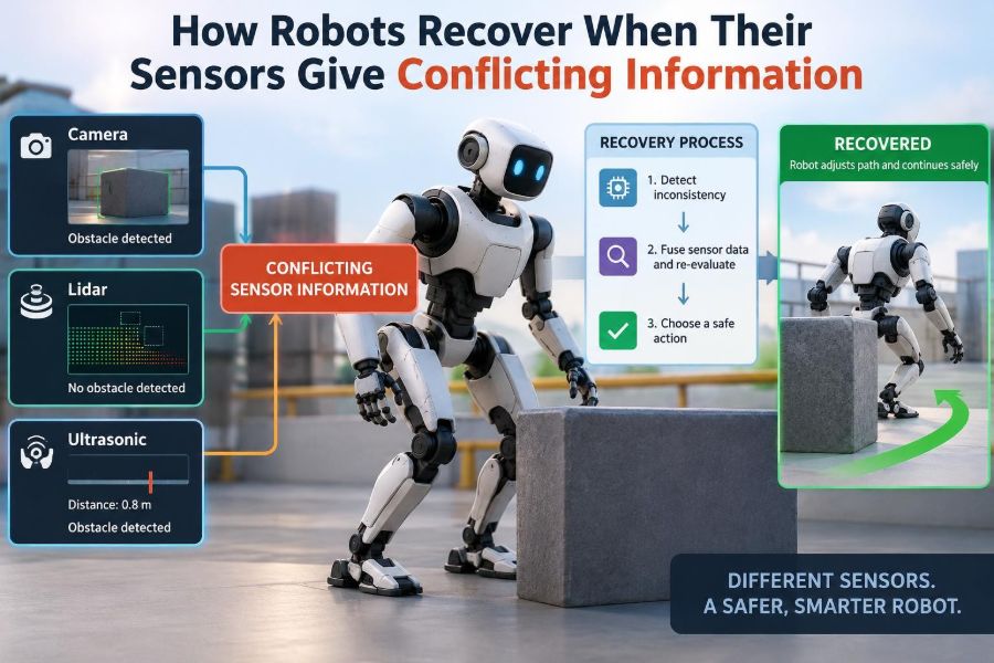

A warehouse robot approaches an aisle that its map says is clear. Its laser scanner reports a solid obstacle. A camera sees only glare from shrink-wrapped pallets, while wheel encoders insist the robot has barely moved. Which sensor should it trust?
People handle this kind of disagreement almost automatically. We glance twice, slow down, touch a surface, or decide that poor lighting makes our eyes less reliable. A robot must make the same kind of judgment explicitly, using software, models, and carefully designed safety behavior.
Conflicting sensor data is not an unusual edge case. It appears in rain, dust, reflections, crowded rooms, electromagnetic noise, loose cables, worn wheels, and software timing faults. Even a healthy sensor can be wrong for a particular task or moment.
The goal is not to find one sensor that never fails. It is to build a robot that can recognize uncertainty, combine evidence intelligently, and move into a safer mode when it cannot know enough to proceed.
🧭 What Sensor Conflict Actually Means
A sensor conflict occurs when two or more measurements imply states that cannot all be true within expected error. For example, an inertial measurement unit may indicate a sharp turn while a camera-based tracker indicates straight travel.
Conflict is broader than a single “bad reading.” It can be a mismatch between a sensor and a map, a sensor and the robot’s motion model, or two sensors that observe the same physical quantity differently. Detecting the mismatch is the first step; deciding what it means is harder.
👁️ The Robot’s Partial View of Reality
Robots do not observe the world directly. They estimate hidden quantities such as position, speed, object distance, surface type, or a person’s pose from imperfect measurements. This estimated internal description is often called the robot’s state or belief about the world.
Each sensor sees a different slice of reality. A camera can identify visual features but struggles in darkness. A lidar measures distance well but may be confused by glass, heavy rain, or certain reflective surfaces. Agreement is useful precisely because their weaknesses are different.
📡 Common Sensors and Their Blind Spots
Knowing a sensor’s failure modes is more useful than simply knowing its specification sheet. Reliability changes with the environment, installation, maintenance condition, and task.
| Sensor | Useful signal | Typical difficulty |
|---|---|---|
| Camera | Appearance, texture, landmarks | Low light, glare, occlusion, motion blur |
| Lidar | Shape and distance | Rain, dust, glass, reflective or absorbent surfaces |
| Radar | Range and relative motion | Lower spatial detail, multipath reflections |
| IMU | Acceleration and rotation | Bias drift and vibration |
| Wheel encoders | Wheel rotation | Slip, uneven wear, lifted wheels |
| GPS/GNSS | Global outdoor position | Blocked sky view and reflected signals |
A robust design uses this knowledge to predict when a measurement deserves less confidence.
⚖️ Why Disagreement Is Not Always a Fault
Two sensors can disagree because they measure different things, at different locations, or at different times. A bumper detects physical contact at the robot’s body, while a lidar may see an obstacle ahead of it. That is not a contradiction.
Likewise, a camera may correctly report that a moving person changed position while a static map correctly describes the building. Engineers must define what measurements should agree under which conditions before treating a difference as evidence of failure.
⏱️ Time Alignment Comes Before Comparison
A fast-moving robot can travel a meaningful distance between a camera frame and a range scan. If software compares them as though they were captured simultaneously, ordinary motion can look like sensor conflict.
Systems therefore timestamp measurements, account for communication delay, and transform readings using the estimated robot motion. Clock synchronization is not glamorous, but it prevents many false alarms and poor fusion results.
📐 Coordinate Frames Can Create Imaginary Problems
Every sensor reports data in its own coordinate frame. A camera sees points relative to its lens, an IMU reports motion along its mounting axes, and a map uses a global frame. Software must know the exact position and orientation of each sensor relative to the robot.
A small calibration error can make a perfectly good camera and lidar appear to disagree about the same wall. Before replacing hardware, teams should check transformations, units, axis conventions, and whether a sensor was physically bumped or remounted.
🔧 Calibration Keeps Measurements Comparable
Calibration estimates systematic relationships: a camera’s lens behavior, a lidar’s alignment, an encoder’s scale, or an IMU’s offset. Unlike random noise, systematic error shifts measurements in a repeatable direction.
For instance, a miscalibrated wheel radius makes encoder-based distance consistently wrong. Fusion software may keep “correcting” the estimate with other sensors, but the underlying disagreement will return until the mechanical or calibration issue is fixed.
📉 Noise, Bias, and Drift Are Different Problems
Noise is rapid, largely unpredictable variation around a value. Averaging or filtering can reduce its effect, although excessive smoothing adds delay. Bias is a persistent offset, such as an accelerometer reading slightly high while stationary.
Drift is accumulated error over time. An IMU can track fast turns well but cannot indefinitely provide an accurate position by integrating acceleration alone. Good recovery logic identifies the pattern, because a noisy sensor deserves a different response from a drifting one.
🧮 Sensor Fusion: Combining Evidence
Sensor fusion combines measurements and a model of robot motion to estimate state more reliably than any single input. Rather than asking “which sensor is right?” fusion often asks “what state best explains all credible evidence?”
A mobile robot may predict its next position from wheel encoders and IMU data, then use lidar landmarks or camera features to correct accumulated error. The prediction is valuable when external observations briefly disappear; the observations limit long-term drift.
🔮 The Role of a Motion Model
A motion model describes what changes are physically plausible. If a ground robot was commanded to drive straight at low speed, an estimated instant sideways jump is suspicious unless another observation strongly supports it.
Models are simplifications, not truth. Wheels can skid, payloads can shift, and people can push a robot. Recovery systems need enough flexibility to admit unusual events without accepting impossible measurements too easily.
📊 Confidence Is More Useful Than a Single Answer
A mature estimator produces not only an estimated position or object location but also an uncertainty measure. It may effectively say, “the robot is probably here, within this region,” rather than claiming a false level of precision.
Uncertainty should influence behavior. A robot that is uncertain about its pose may slow down, enlarge its obstacle margin, pause for a better scan, or avoid a narrow passage. Confidence is an operational input, not just a diagnostic number.
🧠 Bayesian Thinking Without the Mystery
Many fusion methods follow a Bayesian idea: begin with a prior belief based on previous state and motion, then update that belief using new evidence. Measurements that are expected to be noisy should shift the estimate less than measurements expected to be precise.
This does not require every application to run a textbook Bayesian algorithm. The practical lesson is simple: use prior knowledge, quantify uncertainty where possible, and revise beliefs in proportion to evidence quality.
🧷 Kalman Filters for Near-Gaussian Problems
A Kalman filter is a widely used estimator for systems whose uncertainty can be approximated with means and variances. It alternates between prediction from a system model and correction from sensor observations.
Extended and unscented variants address some nonlinear behavior, such as orientation and curved motion. They are powerful but not magic: incorrect noise assumptions, poor timing, or unmodeled slip can produce confident-looking estimates that are wrong.
🎲 Particle Filters for Multiple Plausible Locations
When a robot could be in several distinctly different places, particle filters can represent multiple hypotheses. Each particle represents a possible state, and measurements increase or decrease its plausibility.
Consider a robot in a building with several similar-looking corridors. A camera may initially match more than one corridor. A particle-based approach can keep alternatives alive until later evidence, such as a unique doorway or turn, resolves the ambiguity.
🚨 Innovation Checks Flag Surprising Measurements
In filtering, the difference between a predicted measurement and the actual measurement is often called an innovation or residual. A large residual means the observation was surprising given the current belief.
Systems compare that residual with expected uncertainty. A slight mismatch may be normal noise. A severe mismatch can trigger down-weighting, a fault flag, or a request for further observations. The threshold must account for context; an aggressive threshold rejects useful data, while a loose one admits outliers.
🧹 Outlier Rejection Stops One Reading Taking Over
An outlier is a measurement that is implausible relative to the model and other evidence. It may come from glare, a lidar return from rain, a false visual feature match, or a transient communication error.
Common protections include range checks, rate-of-change limits, consistency tests, and robust loss functions that reduce the influence of extreme residuals. Rejecting data has a cost, though: an unusual measurement may reveal a real event, such as a collision or sudden wheel slip.
🩺 Fault Detection Is More Than Filtering
Filtering manages ordinary uncertainty. Fault detection asks whether a sensor, its wiring, its power supply, or its processing chain may be unhealthy. A frozen value, impossible temperature, repeated checksum errors, or persistent disagreement can all be diagnostic clues.
Fault isolation then attempts to identify the source. If several independent sensors conflict with one camera, that camera becomes suspect. If all position-related signals shift after a map update, the map frame or software configuration deserves inspection.
🗳️ Redundancy Is Not Just Majority Voting
Three similar sensors can support voting, but majority voting is only safe when their errors are sufficiently independent. Three cameras facing the same sun, or three GNSS receivers under the same obstructed sky, may fail together.
Useful redundancy is often diverse: wheel encoders, IMU, lidar, camera, radar, and contact sensing provide different physical evidence. Diversity increases engineering complexity, yet it reduces the chance that one environmental condition blinds every source at once.
🌦️ Context-Aware Trust Changes With Conditions
A robot should not assign a camera the same confidence at noon glare, in a dim corridor, and under a clean work light. Likewise, wheel encoder trust should drop when acceleration patterns suggest slipping on loose gravel.
Context may come from sensor self-reports, weather detection, image exposure, vibration levels, wheel current, or known map zones. This approach is often called adaptive weighting: the fusion system adjusts influence based on estimated measurement quality.
🪟 A Glass Door Is a Classic Multi-Sensor Test
Imagine a delivery robot approaching a glass door. A camera may recognize the frame, lidar may receive weak or inconsistent returns from the glass, and a bumper has no reading because contact has not happened. The map may label the door as an entrance.
A poor design might treat missing lidar returns as clear space. A safer design recognizes low-confidence range data, compares it with visual structure and map expectations, reduces speed, and maintains a stop distance. If uncertainty remains, it waits or requests assistance rather than guessing.
🚜 Wheel Slip Shows Why Internal Sensors Need Checks
Suppose a warehouse robot crosses a dusty patch. Its encoders report wheel rotation, so odometry estimates forward motion. An IMU may show acceleration inconsistent with that distance, while lidar scan matching suggests the robot has not advanced as expected.
That combination indicates possible slip. The robot can reduce acceleration, revise its pose uncertainty upward, rely more on external landmarks, and avoid precision maneuvers until it relocalizes. The encoders were not “lying”; they accurately measured rotation, not ground travel.
🧍 Moving Objects Complicate Perception
A robot may see a shelf edge in one scan and a person passing in the next. A mapping system that assumes the world is static can mistake the person for a localization landmark, producing inconsistent pose estimates.
Modern perception pipelines often distinguish persistent structure from dynamic objects. They track moving detections separately, use temporal consistency, and avoid adding uncertain observations to long-term maps. This separation improves both navigation and safety.
🗺️ Maps Can Be Wrong Too
A map is another source of information, not an unquestionable authority. Furniture moves, construction changes corridors, and facilities add temporary barriers. An outdated map can disagree with several healthy sensors.
Robots should represent map confidence and distinguish stable infrastructure from likely change. In some applications, the correct recovery action is to update a local map; in others, especially regulated or safety-critical settings, the robot should stop and require validated map maintenance.
🛑 Safe Degradation Is a Designed Behavior
When uncertainty rises, a robot needs a defined fallback mode. This may mean slowing, limiting speed and turning, using a smaller operating area, returning to a known landmark, stopping in place, or transitioning control to a human operator.
There is no universal response. An inspection drone with uncertain altitude and a robot arm with uncertain joint position face different hazards. The fallback must be derived from a hazard analysis of what the robot can safely do with reduced sensing.
🧯 Fail-Safe and Fault-Tolerant Are Not Synonyms
A fail-safe system moves to a condition that minimizes hazard when a fault occurs, often stopping motion or removing power from an actuator. A fault-tolerant system continues performing some function despite a fault, usually through redundancy or reconfiguration.
Continuing is not always safer. A surgical, industrial, or autonomous system may need carefully bounded behavior rather than a simple stop, but that decision requires domain-specific validation. Engineers should avoid calling a system fault-tolerant merely because it detects an error.
🧪 Test Conflicts Before Customers Find Them
Recovery behavior should be tested deliberately, not inferred from ordinary successful runs. Teams can inject stale timestamps, blocked camera views, artificial sensor noise, dropout sequences, encoder scale errors, and false range returns in simulation and controlled hardware tests.
Testing should also include combinations. Real failures often interact: vibration degrades vision while a loose connector causes intermittent IMU data. A useful test asks whether the robot detects the condition, selects an appropriate fallback, logs enough evidence, and recovers predictably.
🪵 Simulation Helps, but Reality Sets the Limits
Simulation is excellent for repeated fault injection and dangerous scenarios, but simulated sensors rarely capture every reflection, material property, weather effect, cable problem, and timing issue. Passing a simulated conflict test is evidence of software behavior, not proof of field robustness.
Physical testing should progress cautiously from benign, controlled conditions to representative environments. Instrumentation, protective boundaries, and manual emergency controls are particularly important when validating recovery actions around people or valuable equipment.
📋 Logging Turns Failures Into Engineering Evidence
When a robot behaves strangely, a final error message is rarely enough. Engineers need synchronized records of raw sensor data, timestamps, estimated state, uncertainty, control commands, software versions, and fault decisions.
Logs make it possible to replay an incident and determine whether the issue began with a sensor, calibration, timing, estimator assumptions, map data, or controller behavior. They also reveal near-misses: periods when uncertainty rose but the robot recovered before a visible failure.
🔒 Treat Sensor Trust as a Security Concern
Some sensor conflicts arise from accidental environmental effects; others can result from interference, spoofed signals, or manipulated inputs. Systems that rely on external radio positioning, visual markers, or networked data should consider whether those inputs can be misleading as well as noisy.
Defenses include authentication where applicable, plausibility checks against independent sensors, protected update paths, and conservative behavior when a trusted source suddenly changes. Security does not replace safety engineering, but it prevents trust logic from becoming an easy point of failure.
🛠️ A Practical Design Workflow
Start by listing the states the robot must estimate and the decisions that depend on them. Then identify what each sensor directly measures, its expected error, its common failure modes, and whether another source can independently check it.
- Define normal operating conditions and credible off-nominal conditions.
- Set timing, coordinate-frame, and calibration requirements.
- Choose an estimator that represents uncertainty appropriate to the task.
- Define residual checks, fault criteria, and confidence thresholds.
- Specify degraded modes and clear conditions for returning to normal operation.
- Test single faults, correlated faults, and recovery transitions.
The best thresholds are not copied from another robot. They come from measured behavior, task risk, and iterative validation.
⚠️ Common Recovery Design Mistakes
A frequent mistake is hard-coding one “primary” sensor and treating every disagreement as the other sensor’s problem. Another is rejecting surprising measurements without recording them, which hides early signs of environmental change or component degradation.
- Assuming redundant sensors fail independently when they share power, mounting, weather, or software.
- Ignoring timestamp uncertainty and calibration drift.
- Using confidence values that are never connected to planning or control.
- Testing sensor failures but not the transition into and out of degraded modes.
- Allowing automatic recovery to resume high-speed operation before relocalization is credible.
These mistakes often originate in interfaces between teams, where perception, controls, mechanical design, and operations make separate reasonable assumptions.
🤝 Recovery Requires the Whole Robot Stack
Perception can identify a questionable measurement, but planning must understand uncertainty and controls must execute safe limits. Mechanical design affects vibration and sensor alignment; operations affect cleaning, map updates, and maintenance intervals.
A useful architecture exposes health and confidence across these boundaries. Instead of passing only “position equals x, y,” localization can provide uncertainty and status. The planner can then choose a route with wider clearance or halt if the estimate is not suitable for the maneuver.
🎯 The Core Principle: Manage Uncertainty, Not Just Errors
Sensor conflict is unavoidable because robots operate through incomplete, delayed, and sometimes misleading observations. Robust recovery comes from treating disagreement as information: it may indicate normal noise, a changing environment, a broken component, or an unsafe lack of knowledge.
The strongest systems combine calibrated sensors, time-aware fusion, context-sensitive confidence, independent checks, and preplanned degraded behavior. They do not pretend to know more than the evidence supports.
A robot recovers well when it can recognize what it does not know, reduce risk while it learns more, and stop when learning more is not possible in time. That is the foundation of dependable autonomy. 🦾🧭🔍