
A car door moves down a factory line. Within seconds, a robot positions it, welds a seam, checks part of the result, and moves away before the next door arrives. The motion looks effortless, but it is the visible outcome of thousands of design, manufacturing, programming, and safety decisions.
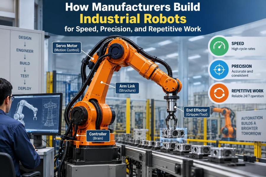
Industrial robots do not become fast and precise merely because they have powerful motors or advanced software. They must be built so that their structure resists flexing, their joints repeat the same position, their wiring survives millions of movements, and their controls react predictably to changing loads.
That challenge appears in far more places than automotive assembly. Robots package food, load CNC machines, apply paint, inspect electronics, stack boxes, and assist with medical-device production. In each case, the machine has to perform a defined task reliably enough that the surrounding process can depend on it.
Understanding how manufacturers build these machines helps students connect mechanics, electronics, materials, and software. It also helps working professionals ask better questions when selecting, installing, or troubleshooting robotic equipment.
🏭 What Makes a Robot Industrial?
An industrial robot is a programmable, automatically controlled machine designed to move tools, parts, or sensors through a work area. Unlike a single-purpose mechanism, it can usually be reprogrammed for related tasks, such as changing from one package size to another.
Most industrial robots have several controlled axes, or degrees of freedom. Each axis changes the position or orientation of the robot, allowing an end-of-arm tool to reach a useful pose: a specific location with a specific angle.
The robot is only one part of a larger robotic cell. Fixtures hold parts, conveyors deliver material, sensors confirm conditions, guards protect people, and a controller coordinates the sequence.
🎯 Start With the Manufacturing Task
Manufacturers begin with the job, not with a robot model. They identify the payload, required reach, production rate, accuracy needs, part variation, environmental conditions, and available floor space.
A robot loading a machine may need to lift a heavy casting but move relatively slowly. A pick-and-place robot for lightweight products may need very high acceleration and short cycle times. These requirements lead to fundamentally different designs.
A useful early question is: what happens when the part is not exactly where expected? The answer may require vision guidance, compliant tooling, better fixturing, or a different process altogether.
📐 Turn Requirements Into a Robot Architecture
Engineers convert the task into an architecture: articulated arm, SCARA, delta robot, Cartesian gantry, or collaborative robot. Each arrangement has strengths that come from its geometry rather than from marketing labels.
| Robot type | Typical strength | Common use |
|---|---|---|
| Articulated arm | Flexible reach and orientation | Welding, machine tending, painting |
| SCARA | Fast planar assembly motion | Electronics and small-part handling |
| Delta robot | Very rapid, light-payload picking | Food and consumer-goods packaging |
| Cartesian robot | Large, straightforward rectangular workspace | Gantry handling and dispensing |
Choosing the right architecture reduces later complexity. A robot can sometimes be forced to perform an unsuitable task, but it may need oversized motors, awkward tooling, or slower operating limits to do so.
🦴 Build a Stiff Mechanical Skeleton
The arm, links, base, and housings form the robot’s structural skeleton. Manufacturers commonly use steel, aluminum alloys, cast components, and carefully designed ribs to obtain stiffness without unnecessary mass.
Stiffness matters because a flexible link bends slightly under load. Even a small deflection at a joint can become a larger positioning error at the tool tip, especially when the arm is extended.
Low mass matters too. A lighter moving link needs less torque to accelerate, which can improve cycle time and reduce energy use. Robot design is therefore a continuous balance between stiffness, weight, manufacturability, and cost.
⚙️ Design Joints for Torque and Repeatability
Each robot joint contains a motor, transmission, bearings, sensors, seals, and supporting structure. These parts must transmit torque while keeping unwanted motion, called backlash or compliance, within controlled limits.
Backlash is lost motion caused by clearances between mechanical elements. If a joint reverses direction and the output does not respond immediately, the tool may miss its intended path. Gearbox selection, preload, and precise assembly help reduce that problem.
Manufacturers often place compact high-ratio transmissions near the joints. This makes it possible to use smaller, faster motors while still generating the torque needed to carry the arm and its payload.
🔩 Choose Gearboxes for the Real Load Case
Robot gearboxes are not selected only by maximum torque. Engineers consider repeated acceleration, reversing motion, shock loads, life expectancy, efficiency, torsional stiffness, and the way each axis supports downstream joints.
Harmonic-drive and cycloidal designs are widely used where compact packaging and low backlash are valuable. Other transmission approaches may suit large axes or specialized machinery. No gearbox is ideal for every load, speed, and budget.
Payload ratings need careful interpretation. The robot carries not only the workpiece, but also the gripper, adapters, cables, hoses, and sometimes a vision camera. The payload’s center of gravity and inertia can be as significant as its mass.
🔌 Match Motors and Drives to the Motion
Most modern industrial robots use servo motors. A servo system combines a motor, feedback device, drive electronics, and control loop so the axis can follow a commanded position, speed, or torque.
Motor sizing considers more than a peak lift. The drive must repeatedly accelerate and decelerate the arm without overheating, exceeding current limits, or producing unstable motion. Engineers analyze torque over an entire duty cycle.
Brakes are commonly fitted to vertical or gravity-loaded axes. Their purpose is generally to hold an axis safely when power is removed, not to stop a moving robot during normal operation.
📍 Measure Position With Encoders
An encoder measures motor or joint rotation and sends that information to the controller. The controller compares measured position with the command and continuously corrects the difference.
High-resolution feedback helps produce smooth motion, but resolution alone does not guarantee real-world accuracy. Gear elastic deformation, thermal growth, assembly tolerances, and load changes can all affect where the tool actually ends up.
Many systems use absolute encoders, which retain position information through power loss. This can reduce the need for a full homing sequence, although safe restart procedures still depend on the cell design.
🧭 Separate Accuracy From Repeatability
Accuracy describes how close the robot reaches an intended coordinate. Repeatability describes how closely it returns to the same coordinate repeatedly. These are related but not interchangeable.
A robot can be highly repeatable while being slightly offset from an ideal mathematical position. In a fixed fixture, that may be acceptable because the programmed path can be calibrated to the real cell. Tasks involving interchangeable fixtures or off-line programming may demand stronger absolute accuracy.
This distinction prevents a common purchasing mistake: selecting a robot based on one specification without considering how parts are presented, measured, and located.
🧮 Use Kinematics to Coordinate Every Axis
Robot kinematics describes the geometric relationship between joint positions and the tool position. Forward kinematics calculates where the tool is when each joint angle is known. Inverse kinematics calculates the joint angles needed to reach a desired tool pose.
For an articulated arm, more than one joint arrangement may reach the same point. The controller chooses a configuration according to limits, collision avoidance, smoothness, and programmed preferences.
Some positions are near a singularity, where the robot loses a useful direction of motion or requires very fast joint movement to maintain a tool path. Good planning avoids or carefully manages these regions.
🧠 Build the Motion Controller
The controller is the robot’s real-time decision center. It reads encoders and sensors, calculates motion trajectories, sends commands to servo drives, monitors faults, and exchanges signals with the rest of the production line.
Control loops run much faster than the visible sequence of “pick, move, place.” Their job is to keep each axis following its path despite inertia, friction, changing loads, and minor disturbances.
Manufacturers tune these loops cautiously. Aggressive settings can make an arm react quickly, but may create vibration, overshoot, audible noise, or instability. Conservative settings may be smooth but waste valuable cycle time.
📈 Plan Paths, Not Just End Points
A robot’s destination is only part of the instruction. The controller must also determine how it moves between positions: joint-by-joint, in a straight tool path, or along a curved path.
For welding, sealing, or cutting, the path and tool speed are part of the process quality. For a simple pick-and-place task, a fast, collision-free route may matter more than a perfectly straight line.
Acceleration and jerk—the rate at which acceleration changes—are limited to protect mechanics and payloads. A robot carrying an open container, for example, may need smoother motion than one moving a rigid metal blank.
🧪 Verify the Design Before Metal Is Cut
Manufacturers use computer-aided design, finite element analysis, and dynamic simulation to explore the robot before building production hardware. These tools can reveal likely stress concentrations, interference between parts, resonance risks, and reachable workspace limits.
Simulation is valuable, but it is not a substitute for physical testing. Material properties vary, cable bundles add resistance, gearboxes behave differently as they warm, and real payloads are not always modeled perfectly.
Digital models are most useful when paired with measured data from prototypes and field machines. That loop turns a plausible design into a dependable product.
🧱 Manufacture Arms, Housings, and Precision Parts
Large structural pieces may be cast, machined, welded, or fabricated from formed metal. Precision bearing seats, gear interfaces, and joint faces require controlled machining because small alignment errors can affect motion quality.
Surface treatment protects components from corrosion and wear. In food, pharmaceutical, foundry, or paint environments, material and finish choices may be driven by washdown, contamination, heat, dust, or chemical exposure.
Production engineers also design for assembly. A component that is theoretically excellent but difficult to align, inspect, or service can raise cost and introduce inconsistent quality.
🧵 Route Cables and Hoses for Millions of Cycles
Power cables, encoder lines, network wiring, pneumatic tubes, and process hoses must travel with the arm. Their routing is a major reliability issue, not an afterthought.
Repeated bending can fatigue conductors, damage insulation, or cause a hose to rub against a moving edge. Manufacturers define bend radii, clamp locations, protective sleeves, and service loops to manage this motion.
External dress packs are easier to inspect and modify, but may snag or restrict movement. Internal routing offers cleaner protection, yet makes repair more involved. The better choice depends on the process and robot geometry.
🛠️ Assemble With Controlled Alignment
Assembly technicians install bearings, gearboxes, motors, seals, brakes, and sensors using specified torques, fits, lubricants, and alignment procedures. A robot is a precision machine; careless assembly can defeat a well-designed drawing.
Preload in bearings and transmission elements must be controlled. Too little can permit vibration and lost motion. Too much can raise friction, heat, and wear.
Traceability is often valuable for critical components. Recording serial numbers, test results, and assembly data helps manufacturers investigate a field issue without guessing which materials or revisions were used.
🧰 Create the End-of-Arm Tool
The robot arm provides motion, but the end effector does the useful work. It may be a gripper, vacuum cup array, welding torch, spray gun, screwdriving spindle, dispensing nozzle, or inspection camera.
Tooling strongly affects performance. An oversized gripper increases inertia and reduces usable payload. A poorly located center of gravity can make the robot vibrate during fast moves. A weak fixture may create variation that no amount of robot precision can solve.
Good tooling includes practical details: part-present sensing, replaceable wear items, cable protection, access for maintenance, and a reliable way to recover from a dropped or misoriented part.
👁️ Add Sensors When the World Varies
Fixed automation works best when every part arrives in the same location and orientation. When that assumption is unrealistic, manufacturers may add photoelectric sensors, force sensors, barcode readers, laser scanners, or machine vision.
Vision can locate a randomly oriented part, inspect a label, or guide a pick. It also introduces its own requirements: stable lighting, usable image contrast, calibration, processing time, and a method for handling uncertain results.
Force or torque sensing can help during insertion, polishing, and delicate assembly. Rather than forcing a rigid programmed path, the controller can adjust motion in response to contact forces.
🧭 Calibrate Robot, Tool, and Workcell
Before production, technicians teach or define coordinate frames. The robot needs to understand its base location, the tool center point, and the position of fixtures or work objects in a common spatial system.
The tool center point is the reference point at the business end of a tool, such as a gripper’s grasp location or a torch tip. If it is calibrated incorrectly, every programmed position can be wrong in a systematic way.
Calibration also connects the robot to external equipment. A vision system, rotary table, or conveyor tracker must use compatible coordinates and timing if parts are to be handled accurately.
🛡️ Engineer Safety Into the Cell
Industrial robots can move quickly, carry heavy loads, and start automatically. Safety therefore depends on the whole installation: risk assessment, guarding, interlocked access points, emergency stops, safety-rated controls, safe speeds, and documented operating procedures.
Collaborative robots can support closer human interaction under certain conditions, but “collaborative” does not mean harmless. Tool shape, payload, pinch points, speed, and the surrounding process all affect the risk.
Safety requirements vary by jurisdiction and application. A qualified integrator and the applicable standards should guide the final design rather than relying on a generic layout.
🔒 Design Safe States and Recovery
A robust cell anticipates faults: a part is missing, air pressure drops, a guard opens, a camera cannot identify an object, or a conveyor stops. The system should move to an appropriate safe state and clearly report what happened.
Recovery matters because production equipment eventually encounters exceptions. Operators need a controlled process to clear a jam, remove a damaged part, verify conditions, and restart without bypassing protective measures.
Ambiguous alarms encourage unsafe workarounds. Clear messages tied to sensors, sequence steps, and practical corrective actions make the cell easier to run responsibly.
🏃 Optimize Cycle Time Without Abusing the Robot
Cycle time is not simply “make every axis faster.” It includes gripping, sensing, communication delays, conveyor timing, machine-process time, safe approach distances, and the time needed to release or verify a part.
Engineers often gain more by eliminating unnecessary motion than by raising speed limits. Shorter paths, better part presentation, overlapping machine and robot activity, and faster tool actuation can improve throughput with less mechanical stress.
Excessive acceleration may shorten component life, shake fixtures, or cause parts to slip. The practical target is stable, repeatable production at a sustainable rate.
🌡️ Test Across Loads and Environments
Factory acceptance testing checks whether a robot and cell meet defined functions before shipment or installation. Tests may cover motion, repeatability, input-output signals, protective functions, payload handling, and expected fault responses.
Manufacturers also evaluate conditions that expose weak points: long run times, maximum approved payload, temperature changes, cable motion, vibration, dust, moisture, and power interruptions where relevant.
A short demonstration is not the same as endurance testing. Repetitive work reveals problems that a few successful cycles can hide, including heat buildup, loosening connections, drifting calibration, and inconsistent gripping.
🏗️ Integrate With Machines and Material Flow
A robot is productive only when it works in rhythm with upstream and downstream equipment. PLCs, machine controllers, conveyors, and safety systems exchange signals that answer basic questions: Is the machine ready? Is a part present? Has the operation finished? Is the area safe to enter?
Handshaking needs defined ownership and failure behavior. For example, if a machine says “cycle complete” but a part-presence sensor disagrees, the cell should not blindly continue.
Material flow is often the true bottleneck. A fast robot cannot compensate for inconsistent trays, damaged pallets, poorly designed infeed, or a process that takes longer than the robot’s available window.
🔧 Plan Maintenance Before Commissioning
Reliable repetitive work depends on preventive maintenance. Typical tasks include inspecting dress packs, checking fasteners, monitoring lubrication requirements, cleaning sensors, confirming safety-device operation, and reviewing fault histories.
Condition monitoring can help identify changes before a failure stops production. Rising motor current, unusual vibration, repeated vision retries, or a gripper taking longer to close may indicate a developing problem, though each signal needs context.
Maintainable cells provide access. If replacing a cable requires dismantling half the cell, repairs will take longer and routine inspection may be skipped.
⚠️ Recognize Common Design Mistakes
Several mistakes recur when teams focus on the robot arm rather than the complete system:
- Selecting by payload alone and ignoring reach, inertia, and center of gravity.
- Assuming repeatability will correct poor fixturing or variable incoming parts.
- Adding vision before fixing lighting, part presentation, or mechanical causes of variation.
- Programming maximum speed before proving tool retention and collision clearance.
- Treating safety and recovery as documentation tasks instead of design requirements.
These problems are avoidable when mechanical, controls, process, quality, and safety teams review the cell together early in the project.
📚 What Students and New Engineers Should Practice
The most useful learning projects combine disciplines. Build a small pick-and-place cell, calculate a payload’s center of gravity, tune a simple servo loop in simulation, or program a camera-guided sorting task with known limitations.
Learn to read drawings, wiring diagrams, pneumatic schematics, robot reach plots, and fault logs. These documents explain why a machine behaves as it does more reliably than trial-and-error adjustments alone.
Also practice writing clear assumptions. If a design depends on identical parts arriving within a narrow positional range, state that requirement. Good engineering makes hidden dependencies visible.
🔭 Where Industrial Robot Design Is Evolving
Manufacturers continue to improve software tools, easier programming interfaces, sensing, connectivity, and energy management. More flexible automation can help facilities handle product variation, shorter runs, and changing labor needs.
That flexibility has limits. A robot still needs a safe workspace, a reliable grasp, appropriate process parameters, and enough time to complete the job. Physical variation cannot always be solved with software.
The most capable systems increasingly combine structured mechanics with perception and data. Rather than replacing careful engineering, those technologies make careful engineering more valuable.
✅ The Core Principle: Build Reliability Into Every Layer
Industrial robots achieve speed, precision, and repetitive performance because every layer supports the next. The structure limits flex, joints transmit motion predictably, feedback measures reality, controls correct error, tooling handles the part, and the cell supplies safe, consistent conditions.
When one layer is weak, the entire system feels it. A highly accurate arm cannot rescue a loose fixture; sophisticated vision cannot make a damaged gripper reliable; fast software cannot overcome an undersized transmission.
The strongest manufacturing approach treats the robot as a system with mechanical, electrical, digital, process, and human elements. That is how a movement repeated thousands of times can remain useful rather than merely impressive.
Industrial robot performance is designed, tested, and maintained as a complete system—not added by the robot arm alone. That systems mindset is the foundation of automation that works shift after shift. 🦾⚙️🏭