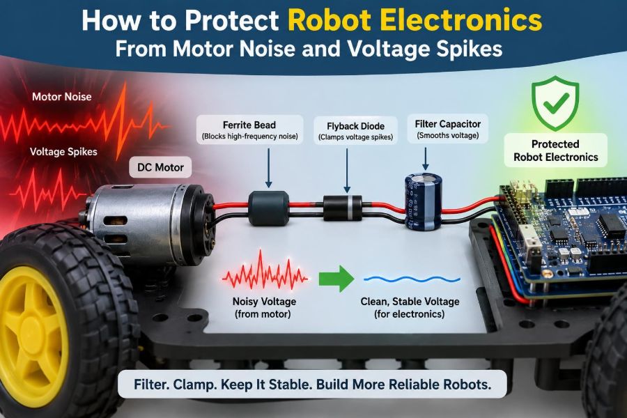

A mobile robot performs perfectly on the bench, then resets the instant its drive motors accelerate. A robotic arm works until its gripper changes direction, when a sensor reading jumps and the controller loses position. These failures can feel random, but they usually have an electrical cause.
Motors are powerful sources of electrical disturbance. They draw large changing currents, switch inductive loads on and off, and can turn long wires into antennas. The same battery, ground, and enclosure that serve the motors often also serve delicate microcontrollers, encoders, cameras, and radio modules.
Protecting robot electronics is not one component or one wiring trick. It is a system design task involving power distribution, grounding, suppression, layout, firmware, measurement, and testing under realistic motion.
This article explains how motor noise and voltage spikes arise, how they enter sensitive circuits, and how to build robots that keep thinking clearly while their motors work hard. ⚡
🤖 1. Recognize the Symptoms of Electrical Noise
Motor-related electrical problems often appear as software faults because the visible symptom is digital. A microcontroller may reboot, an I2C bus may lock up, an encoder count may jump, or a wireless connection may drop when motors start.
Look for a strong connection between the fault and a motor event: acceleration, braking, reversal, stalling, PWM changes, or a particular mechanism reaching its end stop. If the fault disappears when motors are disconnected, power integrity and electromagnetic interference should be early suspects.
- Unexpected resets or brownout messages
- Corrupted sensor values or missed encoder pulses
- Serial data errors and bus communication failures
- Radio range that collapses while motors run
- Controller faults during braking or direction changes
⚙️ 2. Understand Why Motors Create Disturbance
A motor is an electromechanical load, not a simple resistor. Its current changes with speed, torque, supply voltage, load, and control method. Starting from rest or holding a stalled mechanism can demand far more current than normal running.
Motors are also inductive. Inductance resists a rapid change in current, so when a switching device opens, stored magnetic energy can produce a voltage transient. Brushed motors add another source: commutation at the brushes creates rapid current interruptions and electrical arcing.
Fast changes matter because every real wire and trace has resistance, inductance, and capacitance. Even a modest current change can create a significant unwanted voltage if it happens quickly enough.
🔌 3. Separate Voltage Sag From Voltage Spikes
Two failures are commonly grouped together as “motor noise,” but they need different defenses. A voltage sag occurs when motor current pulls the supply rail downward. It can reset logic or force a regulator out of regulation.
A voltage spike is a brief overvoltage transient, often caused by inductive current interruption, regenerative braking, or parasitic inductance in wiring. It can stress drivers, regulators, and input protection circuits.
| Problem | Typical cause | Common symptom | Primary response |
|---|---|---|---|
| Voltage sag | Startup, stall, undersized battery, shared wiring | Reset or sensor failure | Reduce impedance, add energy storage, size supply correctly |
| Voltage spike | Inductive switching, braking, long leads | Driver damage or erratic logic | Clamp energy and control switching paths |
| Radiated interference | Brush arcing, fast PWM edges, cable loops | Encoder or radio errors | Reduce emissions and improve routing and shielding |
📉 4. Calculate the Shared-Wire Voltage Drop
A useful first approximation is V = I × R. If motor current flows through resistance shared with the controller supply or ground return, the controller sees a changed voltage reference. Connectors, battery leads, switches, fuses, thin wires, and PCB copper all contribute resistance.
At fast edges, wire inductance adds another term: V = L × di/dt. This explains why a cable that seems electrically fine at steady current can create sharp transients during PWM switching or motor reversal.
The practical lesson is simple: do not let high, rapidly changing motor current share a narrow path with sensitive electronics.
🧭 5. Map Every Current Loop Before Adding Parts
Draw the current path for each operating state, not merely the schematic connections. Trace current from the battery through the motor driver, motor, and back to the battery. Then trace the controller, sensor, and communication return paths.
Ask where those paths overlap. A shared return segment is especially important because voltage developed there shifts the apparent ground seen by every circuit downstream.
Include temporary test equipment, USB connections, metal frames, and externally powered sensors in the map. These can create unplanned return paths that hide a problem on the bench and reveal it later.
⭐ 6. Use a Deliberate Power Distribution Topology
A robust robot usually distributes battery power outward from a central point or low-impedance bus. The motor branch and logic branch should separate as early as practical, rather than passing logic current through motor wiring or motor-driver terminals.
This is often called a star-style power distribution, although the physical geometry does not need to be a perfect star. The objective is controlled sharing of conductors, not a particular visual shape.
- Give major motor drivers direct, short battery connections.
- Feed logic through its own protected branch and regulator.
- Keep high-current returns short and wide.
- Join returns at a planned low-impedance region near the power source.
🌍 7. Treat Ground as a Voltage Reference, Not a Magical Sink
“Ground” is only a name for a reference node. When current flows through its real resistance and inductance, different points called ground can briefly have different voltages. Sensitive signals measured against a noisy local ground can become unreliable even when the supply voltage appears acceptable.
Avoid routing encoder, analog sensor, and communication returns through high-current motor returns. On a PCB, use a continuous ground plane where possible, then keep noisy switching loops physically compact and away from sensitive signal areas.
Do not disconnect all grounds in an attempt to stop noise. Circuits that exchange ordinary electrical signals still need a defined return path.
🔋 8. Choose a Battery for Transient Demand
A battery must provide both the robot’s average energy and its peak current without excessive voltage drop. Motor startup, acceleration, collisions, climbing, and stall conditions can be much more demanding than steady cruising.
Battery internal resistance, connector resistance, protection circuitry, state of charge, temperature, and lead length all influence the voltage at the driver. A pack that powers a lightly loaded robot may still sag badly under abrupt mechanical load.
Measure battery voltage at the battery and at the driver during a demanding maneuver. The difference reveals losses in the distribution path; both measurements are useful.
🛡️ 9. Protect the Power Entry Point
The power entry is the right place to handle faults that originate outside the electronics enclosure. Consider reverse-polarity protection, an appropriately selected fuse or electronic protection device, and a voltage clamp strategy compatible with the battery and expected transients.
A fuse protects wiring from sustained overcurrent; it is not a fast solution for every voltage spike. Likewise, a transient suppressor must be selected so its working behavior fits the normal supply voltage and so it can survive the energy it is expected to absorb.
Place protection with short, low-inductance connections. A protector connected through long thin traces may react too late at the circuit it is meant to protect.
🧱 10. Add Bulk Capacitance Near Motor Drivers
Bulk capacitors act as nearby energy reservoirs. When a driver demands a sudden pulse of current, a capacitor close to its supply pins can provide part of that pulse instead of forcing all current through long battery leads.
Capacitor selection is not just about a large capacitance value. Voltage rating, equivalent series resistance, ripple-current capability, temperature behavior, and placement all matter. A large capacitor at the far end of a cable cannot fully replace a smaller one mounted close to the switching loop.
Follow the driver manufacturer’s required decoupling guidance, then validate the result under real load.
🧩 11. Combine Bulk and Ceramic Decoupling
Different capacitors are effective over different frequency ranges. Bulk capacitors help with slower load changes and stored energy, while small ceramic capacitors are valuable for fast local switching currents.
Place ceramic decoupling capacitors close to the power and ground pins of microcontrollers, sensors, motor-driver logic supplies, and regulator circuits. Their short connection path is essential; a long trace adds inductance that reduces high-frequency effectiveness.
Think in layers: battery capacity supports the whole system, bulk capacitance supports local power branches, and ceramic capacitors support individual integrated circuits.
🔄 12. Handle Regenerative Braking Safely
When a motor is driven by its load, it becomes a generator. This often happens during fast deceleration, downhill motion, or an externally pushed mechanism. Energy can flow back toward the supply and raise the bus voltage.
Some batteries and battery-management systems can accept limited charging current under certain conditions; others may restrict it. A supply that cannot absorb returned energy can allow bus voltage to rise quickly.
Possible strategies include gentler braking, controlled coast modes, a braking resistor and switch in suitable systems, or a clamp designed for the expected energy. The correct choice depends on the motor, driver, supply, and motion profile.
🪤 13. Give Inductive Current a Safe Path
When switching an inductive load, current needs a path as it decays. Motor drivers commonly provide recirculation paths through internal transistors or diodes. Verify how your specific driver behaves in forward drive, reverse drive, coast, and brake modes.
A simple flyback diode is often appropriate across a single direction-driven coil, such as a relay or solenoid. It is not automatically the correct addition across a bidirectional DC motor controlled by an H-bridge, where it may interfere with intended current paths.
Use the topology required by the driver, not a copied circuit fragment from a different application.
🔥 14. Suppress Brushed-Motor Commutation Noise
Brushed DC motors generate noise at the commutator because brush contact changes repeatedly as the rotor turns. A small capacitor installed directly across the motor terminals can reduce high-frequency emissions by giving that noise a short local path.
Some motor and system designs also use capacitors from terminals to the motor case, or an RC snubber, but values and grounding arrangements must suit the motor, driver, and mechanical enclosure. Poorly chosen capacitors can increase driver switching stress.
Keep suppression parts physically close to the motor terminals, not at the far end of a long cable. 🧯
🧵 15. Keep Motor Leads Short and Twisted
Two separated conductors carrying motor current form a loop. A larger loop radiates and receives more magnetic interference. Twisting the motor supply pair reduces loop area and helps the fields from the two conductors cancel.
Route motor leads away from encoder cables, antenna feeds, analog inputs, and camera connections. If paths must cross, crossing at roughly right angles is generally better than running alongside each other for a long distance.
Use wire gauge appropriate for current and length. A wire that is safe thermally may still have too much resistance or inductance for clean transient performance.
📡 16. Protect Encoders and Low-Level Signals
Encoder signals can be vulnerable because they often travel beside motors and are used for precise timing. A short noise pulse may look like an extra transition, while a supply disturbance may cause an encoder to lose its output state.
Use twisted pairs for a signal and its return when practical. Differential signaling is especially useful for longer or harsher paths because the receiver responds primarily to the voltage difference between the pair rather than noise common to both wires.
For single-ended signals, keep cables short, provide a clean reference return, and use input filtering only after confirming it will not distort legitimate pulse timing.
🎛️ 17. Filter Analog Inputs With Care
Analog sensors can convert power noise, ground movement, and radiated interference into unstable measurements. A simple resistor-capacitor low-pass filter near the receiving input may reduce unwanted high-frequency content.
The filter must preserve the information you need. If a control loop or sampled measurement needs fast changes, excessive filtering creates delay and can make the robot respond poorly.
Use clean analog references where required, route analog signals away from switching nodes, and avoid sharing their return path with motor current. Software averaging can help, but it cannot repair severe electrical interference.
🏗️ 18. Design PCB Layout Around Current Loops
On a motor-control PCB, the highest-current switching loop deserves first attention. Minimize the loop formed by supply decoupling, switching transistors, and the return path. Short, wide copper and closely placed capacitors reduce parasitic inductance.
Keep the motor switching area away from microcontroller clocks, analog front ends, crystals, antenna regions, and sensitive connectors. Avoid sending fast switch-node copper across large areas of the board.
A ground plane is valuable, but it does not excuse poor component placement. Current follows the available geometry; layout determines whether noisy current has a compact path or spreads across the design.
🧰 19. Use Regulators Within Their Real Limits
A logic regulator must tolerate the input range it will actually see, including normal battery voltage, charging conditions where applicable, and plausible transients. It must also remain stable with its specified output capacitors and deliver current during processor, radio, and peripheral peaks.
Linear regulators can be quiet but may waste substantial power when dropping a high battery voltage. Switching regulators are efficient but add their own high-frequency switching noise and need careful layout and filtering.
Check dropout behavior too. During a motor-induced sag, a regulator may no longer maintain its output even though its input has not reached zero.
🚧 20. Isolate Sensitive Loads When It Helps
Power isolation can range from separate regulator branches to fully isolated DC-DC converters and digital isolators. The right level depends on the coupling path and the consequences of failure.
A separate regulator for logic often helps because it reduces direct sharing of supply impedance with motors. But it does not eliminate noise that enters through ground paths, signal cables, or electromagnetic radiation.
True galvanic isolation is useful in some high-energy or externally connected systems, but it adds complexity. Isolate only after understanding the current and signal paths you need to interrupt.
🧲 21. Consider Ferrites and Common-Mode Filtering
Ferrite beads and clamp-on ferrite cores can attenuate high-frequency noise, especially on cables that act as antennas. They are not universal cures for low-frequency voltage sag or a severely undersized power path.
A ferrite around a cable affects common-mode currents, while a component placed in series with a supply rail has a different role. Its useful behavior depends on frequency, current, DC resistance, and installation location.
Use ferrites after improving the fundamental layout, return paths, decoupling, and motor suppression. Otherwise they may only mask an avoidable design problem.
🖥️ 22. Keep Communication Interfaces Robust
Robots often connect controllers, motor drivers, sensors, computers, and external tools through cables. These interfaces can carry noise into otherwise clean electronics, especially when devices have separate power supplies.
Use the appropriate physical layer for cable length and environment. Differential interfaces are generally more tolerant of common-mode noise than simple single-ended logic connections. Provide proper termination only where the interface requires it.
Be cautious with a USB cable connected to a laptop during motor testing. It can establish an unexpected ground route and expose the computer to faults if the robot wiring is incorrect.
🧠 23. Add Firmware Defenses, but Do Not Hide Hardware Faults
Firmware should assume that difficult electrical conditions can occur. Enable brownout detection when supported, use watchdog recovery thoughtfully, validate communication data, and define safe motor behavior after resets or sensor faults.
Logging reset causes and supply-related fault flags can greatly shorten debugging. A controller that simply restarts without leaving evidence makes a power problem look mysterious.
However, software recovery is not a replacement for electrical integrity. Repeated brownouts can corrupt operations, interrupt motion, and stress storage devices. Fix the power path that caused the reset.
🔍 24. Measure the Problem Correctly
A digital multimeter is useful for average voltage but can miss fast sags and spikes. An oscilloscope is usually the most informative tool for observing motor supply rails, logic rails, switch nodes, encoder signals, and the timing relationship between them.
Probe technique matters. A long ground clip creates a loop that can pick up noise and display misleading ringing. Use a short ground spring or another low-inductance probing method when examining fast events.
Useful test points
- Battery terminals and motor-driver supply pins
- Logic regulator input and output
- Controller reset line and critical communication lines
- Motor terminals during switching and braking
🧪 25. Test Worst-Case Mechanical Conditions
Quiet bench tests are not enough. Test the robot while starting from rest, reversing rapidly, climbing, carrying payload, pushing against resistance, and approaching legitimate stall conditions. Exercise all motors together if that can happen in service.
Also test with a partly discharged battery, realistic cable routing, installed covers, active radios, and connected sensors. A configuration that works with the chassis open and one wheel lifted may fail when the final wiring harness is installed.
Change one factor at a time when investigating. This makes the relationship between cause and effect much easier to establish.
📝 26. Build a Repeatable Debugging Sequence
Start with safety: secure the robot, limit motion, and avoid accidental shorts. Then reproduce the failure while recording supply voltage and reset behavior. Disable or substitute loads to identify which motor event triggers the disturbance.
Inspect connectors, crimps, solder joints, wire gauge, capacitor polarity, and grounding routes before making complex changes. Mechanical vibration can turn a marginal electrical connection into an intermittent fault.
- Confirm the symptom and trigger.
- Measure at the load and source.
- Find shared current paths and cable loops.
- Improve distribution and local decoupling.
- Add appropriate suppression or clamping.
- Retest under the same worst-case maneuver.
✅ 27. Apply the Core Principle: Control Energy and Return Paths
Reliable robot electronics come from controlling where current flows, where inductive energy goes, and how closely sensitive circuits share those paths. Keep high-current loops compact, provide local energy storage, separate noisy and sensitive branches early, and route signals with intentional returns.
Then verify the design with measurements during real motor events, not assumptions based on average current. Components such as capacitors, clamps, ferrites, and filters work best when they support a sound physical layout and power architecture.
The core principle is to give motor current and transient energy short, controlled paths that never force sensitive electronics to absorb the consequences. Build and test around that principle, and resets, false readings, and damaged drivers become far less likely. ⚡🤖🛡️