
A robot arm reaches for a mug. A warehouse vehicle slows before a worker crosses its path. A small wheeled rover corrects its course when one tire slips on a dusty floor. From the outside, these actions can look smooth and almost effortless.
Underneath, motion is a constant conversation between hardware and software. The robot must detect what is happening, decide what to do next, send power to its motors, and check whether the resulting movement matched its intention.
That cycle is what separates a robot from a simple machine that repeats the same motion regardless of what changes around it. It is also why a robot that moves well on a lab bench can behave very differently in a crowded factory, a home, or outdoors.
Understanding this chain—from sensing to decision to actuation—helps students debug designs and helps working engineers make safer, more reliable systems. The individual parts matter, but the connections between them matter even more.
🧩 A Robot Is a Closed-Loop System
Most useful robot motion is based on a closed loop. The robot measures its current condition, compares that measurement with a desired condition, acts to reduce the difference, then measures again.
Suppose a mobile robot should travel at 0.5 meters per second. If an encoder reports that a wheel is turning too slowly, the controller can increase motor command. If the robot is already moving too quickly, it can reduce it. This repeated correction is called feedback control.
An open-loop machine simply sends a command and assumes the result occurred. Open-loop control can work for predictable, low-risk tasks, but it cannot naturally compensate for a weak battery, extra payload, friction, or a collision.
🎯 Motion Begins with a Goal
Before a motor turns, a robot needs a target. The target might be a wheel speed, a joint angle, a gripper force, a location on a map, or a path through a work area.
Goals exist at different levels. A task planner might decide, “move the box to shelf B.” A motion planner converts that task into a collision-free route. Lower-level controllers then turn the route into precise wheel speeds or joint positions.
This hierarchy prevents a motor controller from having to understand warehouse inventory or object recognition. Each layer solves a problem at the scale where it makes sense.
👁️ Sensors Give the Robot Evidence
Sensors do not give a robot perfect knowledge; they provide measurements that the robot must interpret. An encoder may report rotation, an IMU may report acceleration and angular rate, and a camera may provide patterns of light that software identifies as objects.
Every sensor has limitations. Measurements can be noisy, delayed, blocked, biased, or sampled too slowly. A well-designed robot treats sensor output as evidence with uncertainty, not as unquestionable truth.
The choice of sensor depends on the question being asked. A motor encoder is excellent for shaft rotation but cannot by itself tell whether a wheel is slipping across the floor.
📏 Proprioception: Sensing the Robot Itself
Proprioceptive sensors describe the robot’s own body and internal state. They include joint encoders, motor current sensors, temperature sensors, battery monitors, and inertial measurement units.
Joint encoders let a robotic arm estimate where each link is. Current sensing can indicate how much electrical effort a motor is drawing, which is often useful for torque estimation and overload detection. Temperature monitoring helps protect motors and power electronics from sustained stress.
These sensors are the robotic equivalent of feeling limb position, muscle effort, and balance. Without them, accurate controlled movement becomes much harder.
🌍 Exteroception: Sensing the Outside World
Exteroceptive sensors measure the environment beyond the robot. Examples include cameras, lidar, radar, ultrasonic sensors, tactile arrays, force sensors, and bump switches.
A depth camera can help a robot identify an obstacle’s shape, while a lidar can measure distance across a wider field of view. A tactile sensor in a gripper can reveal that an object has been touched even when vision is obscured.
External sensing is essential when the environment changes. A preprogrammed route may work in an empty corridor, but it is insufficient if people, carts, doors, and misplaced objects share that corridor.
🔢 From Raw Signals to Usable Measurements
A sensor signal is often not immediately meaningful. A quadrature encoder produces pulses; software counts and times them to estimate position and speed. A camera produces pixels; computer vision turns selected patterns into features, poses, or object labels.
Signal processing may filter electrical noise, calibrate offsets, convert units, and reject implausible readings. For example, a range sensor reporting a sudden impossible jump might be temporarily ignored rather than treated as an obstacle teleporting across the room.
Filtering must be balanced carefully. Heavy filtering can make a signal smoother but also adds delay. In a fast balancing robot, delayed feedback can be as harmful as noisy feedback.
🧠 Sensor Fusion Builds a Better Estimate
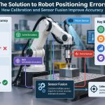
No single sensor usually tells the complete story. Sensor fusion combines measurements to estimate quantities that are difficult to observe directly, such as a robot’s location, orientation, or velocity.
Consider a wheeled robot. Wheel encoders estimate distance traveled but accumulate error during slip. An IMU responds quickly to turns and acceleration but gradually drifts. A camera or lidar may provide environmental references that correct longer-term drift.
Fusion algorithms range from simple weighted averages to probabilistic estimators such as Kalman filters. The correct method depends on the robot, its computational budget, the expected noise, and the consequences of an incorrect estimate.
🗺️ Localization Answers “Where Am I?”
Localization estimates a robot’s position and orientation relative to a map, workspace, or reference frame. A robot arm may localize its tool tip relative to its base; an autonomous vehicle may localize its body within a building.
Small position errors can have large consequences. If a pick-and-place arm thinks a part is five millimeters away from where it really is, its gripper may miss a narrow feature. If a mobile robot’s heading estimate drifts, it may gradually steer into a boundary.
Localization is never merely a navigation concern. It also supports accurate manipulation, inspection, docking, and safe stopping zones.
🧭 Coordinate Frames Keep Geometry Consistent
Robots use coordinate frames to describe position and orientation consistently. Common frames include the world frame, robot base frame, camera frame, tool frame, and individual joint frames.
A camera might detect an object 40 centimeters ahead in its own frame. To grasp it, the robot must transform that location into the arm base frame and then into joint targets. A small mistake in calibration or frame direction can produce motions that look mysteriously reversed or offset.
Clear frame naming, documented conventions, and repeatable calibration are practical engineering habits, not mathematical decoration.
🦴 Kinematics Connect Joints to Motion
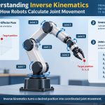
Kinematics describes geometry without considering the forces that cause movement. Forward kinematics calculates where a robot’s end effector will be when its joint angles are known.
Inverse kinematics works in the opposite direction: given a desired tool position and orientation, it finds joint configurations that can reach it. Some targets have several valid solutions, while some are physically unreachable.
For a two-link planar arm, moving the hand to a point may require choosing an “elbow up” or “elbow down” posture. The choice can affect collision risk, cable routing, speed, and how close the arm comes to a joint limit.
⚖️ Dynamics Explain Force, Mass, and Momentum
Dynamics adds forces and torques to the geometric picture. It accounts for mass, inertia, gravity, friction, payloads, and acceleration.
A robot arm can hold a light empty gripper with little effort, yet require much more joint torque when carrying a heavy object far from its base. Rapidly accelerating that same load demands additional torque because the robot must overcome inertia.
Dynamic models help generate smoother, more accurate motion. They are especially useful for fast arms, legged robots, drones, and systems where gravity or changing payloads significantly affect performance.
🛤️ Planning Chooses a Feasible Route
Planning determines how to get from the current state to the desired state while respecting constraints. For a mobile robot, constraints may include walls, people, turning radius, traction, and no-go zones. For an arm, they include collisions, joint limits, and singular configurations.
A path is not automatically a usable motion. A geometric route that passes through free space may still require impossible acceleration or an unsafe cornering speed. Good planning considers the robot’s physical capabilities as well as the map.
Plans should also be revised when reality changes. A blocked aisle, shifted pallet, or unreliable localization estimate can make an originally valid plan unsuitable.
⏱️ Trajectories Add Time to a Path
A trajectory specifies not only where the robot should go, but when it should be at each point and how quickly it should move. It commonly includes position, velocity, and acceleration targets over time.
Trajectory shaping avoids abrupt commands. Asking a motor to jump instantly from rest to high speed can exceed available torque, cause wheel slip, excite structural vibration, or draw damaging current.
Acceleration and jerk—the rate at which acceleration changes—matter for delicate handling. A robot carrying liquid, glassware, or an instrument may need a slower, smoother trajectory than one moving a rigid metal part.
🧮 The Controller Turns Error into Action
A controller compares the desired state with the estimated current state. The difference is called the error. It then produces a command intended to reduce that error.
At a wheel, the controller may compare desired and measured speed. At a joint, it may compare desired and measured angle. At a vehicle level, it may compare desired and estimated heading.
Controllers operate repeatedly, often many times per second. Their job is not simply to “move the motor”; it is to keep movement on target while conditions change.
🎛️ PID Control Is Common, Not Magical
A widely used controller is PID: proportional, integral, and derivative control. The proportional term reacts to present error. The integral term accumulates persistent error. The derivative term reacts to the error’s rate of change.
| Term | Primary role | Common risk if overused |
|---|---|---|
| Proportional (P) | Pushes harder when error is larger | Oscillation or overshoot |
| Integral (I) | Removes steady bias, such as drag | Windup and slow recovery |
| Derivative (D) | Damps rapid change | Amplifying measurement noise |
PID is popular because it is understandable and effective for many well-defined loops. It is not a universal solution: poor sensors, mechanical backlash, unmodeled delays, and unsuitable targets cannot be fixed just by changing gains.
📈 Tuning Is a Stability and Performance Trade-Off
Controller tuning chooses gains and limits that produce acceptable behavior. A sluggish system may need stronger correction; an oscillating system may need less aggressive correction or more damping.
The desired response depends on the job. A camera gimbal benefits from smooth, stable settling. A collision-avoidance subsystem may prioritize quick braking. An industrial arm may need repeatability without shaking the fixture.
Tune under realistic conditions. A controller that behaves well with an empty gripper may become unstable or slow with a heavier payload, a lower battery voltage, or a warmer motor.
🔌 Commands Reach the Motor Through Power Electronics
A controller usually does not power a motor directly. It sends a low-power command to a motor driver, sometimes called an amplifier or inverter. The driver switches electrical power from the battery or supply into the motor windings.
For a brushed DC motor, an H-bridge can reverse voltage polarity and use pulse-width modulation, or PWM, to regulate average power. Brushless motors require electronically timed phase currents, often controlled by a dedicated drive.
Power electronics must be sized for voltage, current, heat dissipation, and transient conditions. A control algorithm may request torque, but a driver with insufficient current capacity cannot physically deliver it.
⚙️ Motors Convert Electrical Energy into Torque
Motors turn electrical energy into rotational torque. The robot then uses that torque directly or transmits it through gears, belts, chains, screws, or linkages to create useful movement.
Motor selection involves more than top speed. Engineers consider continuous and peak torque, efficiency, thermal limits, inertia, voltage, control method, and the load’s duty cycle. A motor that briefly lifts a load may overheat if asked to hold that load for long periods.
Different motor types serve different needs. Stepper motors can be useful in controlled positioning applications, while servo systems with encoder feedback are often chosen when disturbance rejection and accurate motion are needed.
🔧 Transmissions Trade Speed for Force
A gearbox can reduce output speed while increasing available torque. This is valuable when a small, fast motor must move a heavier joint or wheel. Belt drives can relocate motor mass, and lead screws convert rotation into linear motion.
Every transmission introduces trade-offs. Gears may add backlash, belts may stretch, and high reduction ratios can limit backdrivability—the ability to move an unpowered mechanism by pushing it.
Backdrivability can be desirable for collaborative or compliant robots, while high stiffness can be preferable for precise machining. Mechanical design and control strategy must be chosen together.
🦾 Actuators Move More Than Rotating Shafts
An actuator is any device that creates controlled physical action. Electric motors are common, but robots may also use pneumatic cylinders, hydraulic actuators, shape-memory devices, or linear motors.
Pneumatics can provide fast, simple motion but compressible air makes fine position control more challenging. Hydraulics can produce high force, yet add pumps, hoses, leakage concerns, and maintenance demands.
The best actuator is application-specific. A lightweight laboratory gripper, a construction machine, and a soft rehabilitation device face very different force, cleanliness, precision, and safety requirements.
🤝 Compliance Makes Contact More Manageable
Not every task should be controlled as a rigid position problem. When a robot inserts a peg, wipes a surface, or hands over an object, contact forces matter as much as geometry.
Compliance means allowing controlled flexibility in the mechanism or software. Series elastic actuators place an elastic element between motor and load, while impedance control makes a robot behave as if it had a chosen virtual spring and damper.
Compliance can reduce impact and help a robot accommodate small errors. It also complicates precision, because flexible systems can oscillate and require careful sensing and control.
🧱 Friction, Backlash, and Flexibility Change Reality
Mechanical behavior often explains problems that appear to be software failures. Static friction can keep a joint still until torque crosses a threshold. Backlash creates a small dead zone when gears reverse direction. Flexible links and mounts can vibrate after a rapid stop.
These effects make a robot’s response nonlinear: doubling a command does not always double the movement. A controller designed only around an ideal model may chatter at low speeds or overshoot when direction changes.
Measure the real mechanism where possible. Better bearings, stiffer mounts, suitable preload, and thoughtful transmission design can be more effective than increasingly complicated software.
🔄 Feedback Closes the Motion Loop
After the actuator moves, sensors report what happened. The controller then corrects the next command. This loop runs continuously while the robot operates.
Imagine a mobile robot climbing a slight ramp. The motor command that worked on level ground may no longer maintain speed. Encoder feedback reveals the slowdown, and the controller can increase effort within safe limits.
Feedback does not create unlimited capability. If the required torque exceeds the motor, driver, or battery limit, the robot cannot maintain the target. A good system recognizes saturation rather than pretending the command was achieved.
🚦 Timing and Latency Affect Control Quality
Control depends on timely information. Latency is the delay between an event, its measurement, computation, and response. Delays arise in sensing, filtering, communication, scheduling, and actuation.
A slow camera pipeline may be acceptable for inventory identification but unsuitable as the only feedback source for a fast balancing maneuver. Similarly, network jitter can make a distributed control loop inconsistent.
Engineers separate time-critical loops from slower planning tasks when needed. A motor drive may regulate current locally at high rate, while a higher-level computer updates motion targets at a lower rate.
🛑 Safety Is Part of the Control Architecture
Safe robot motion requires more than an emergency-stop button. The system should recognize limits, detect faults, constrain commands, and transition to predictable states when information becomes unreliable.
Typical protections include hardware limit switches, software travel limits, current limits, speed limits, watchdog timers, guarded workspaces, and fault states that disable or brake motion appropriately for the application.
Safety behavior must be tested in realistic failure cases: unplugged encoders, stale sensor messages, obstructed joints, low battery conditions, and restarted computers. The appropriate measures depend on the robot’s energy, environment, and applicable safety requirements.
🔋 Power Limits Shape What Motion Is Possible
Every movement draws energy. Fast acceleration can demand high current, causing voltage sag in batteries or power supplies. Lower voltage can reduce available motor speed and torque, which changes the response the controller sees.
Power distribution therefore affects motion quality. Undersized wiring, inadequate connectors, poor grounding, and shared supplies can introduce heating, voltage drop, or electrical noise into sensor signals.
Designers should budget for normal operation and plausible peak demand, while recognizing that sustained peak operation is often thermally limited. Electrical, mechanical, and control decisions cannot be treated as separate worlds.
🧪 A Mobile Robot Example from Goal to Wheel
Consider a hypothetical delivery robot asked to drive to a marked station. Its navigation layer selects a route and issues a desired forward speed and turning rate.
Wheel-speed targets are generated from those commands. Encoders measure actual wheel rotation, an IMU estimates turning behavior, and a localization system checks the robot’s position against its map. The wheel controllers command motor drivers, which regulate motor power.
If the right wheel encounters a slippery patch, its encoder may indicate rotation without corresponding forward progress. Comparing encoder, IMU, and localization evidence can reveal the mismatch. The robot may reduce acceleration, adjust steering, or replan rather than blindly insisting on the original motor command.
🖐️ A Robot Arm Example at the Moment of Contact
Now consider a hypothetical arm inserting a connector into a fixture. Vision estimates the connector location, kinematics finds a reachable joint configuration, and trajectory generation produces a smooth approach.
Near contact, pure position control can be risky because small alignment errors may create excessive side force. A force sensor or motor-current estimate can provide contact evidence, allowing the robot to slow, search gently within a limited range, or stop if force exceeds a safe threshold.
The key lesson is that sensing changes with the phase of the task. Vision may guide the approach, while force feedback becomes more useful when surfaces touch.
🐛 Debugging Means Following the Signal Chain
When a robot moves incorrectly, start by asking where the mismatch begins: the goal, estimate, plan, control command, driver output, or mechanism. Changing controller gains first can hide the actual cause.
- Verify sensor units, signs, offsets, timestamps, and coordinate frames.
- Log desired values alongside measured values and motor commands.
- Test one subsystem at a time before integrating the full robot.
- Inspect mechanical play, loose couplings, wiring faults, and power sag.
- Use safe speed and torque limits during early experiments.
A useful test is to command a simple repeatable motion, such as a slow joint sweep or straight drive, then compare expected and measured behavior. Simple tests make patterns easier to isolate.
⚠️ Common Design Mistakes and Better Alternatives
One common mistake is assuming encoder accuracy equals real-world position accuracy. Encoders measure motor or wheel rotation; they do not directly measure a slipping wheel’s travel or a flexible arm tip’s location. Add appropriate external sensing or account for uncertainty.
Another is tuning control before fixing poor mechanics. If a gear train has significant backlash or a bracket flexes, software can mitigate symptoms but may not solve the root problem.
A third is ignoring saturation. Integral control can keep accumulating error when a motor is already at its limit, then cause a large overshoot once the load changes. Anti-windup logic and realistic command limits help prevent this behavior.
📊 Measure Before You Optimize
Robotics improves quickly when decisions are based on recorded behavior. Log sensor values, target states, controller outputs, loop timing, faults, supply voltage, and temperatures where relevant.
Plots can reveal whether a system is oscillating, lagging, clipping at a power limit, or responding to noisy measurements. A video synchronized with logs is often particularly valuable because it connects numbers to physical events.
Build tests around meaningful requirements: maximum stopping distance, repeatable placement error, acceptable settling time, or safe contact force. Vague goals such as “make it smoother” are harder to validate and maintain.
🧱 Design the Whole Motion Stack Together
Strong robot motion comes from co-design. A lighter arm may need smaller motors. Better sensing may reduce the need for extreme mechanical precision. A more compliant transmission may demand different control bandwidth and safety limits.
Early prototypes should expose assumptions. Test payload variation, surface changes, temperature effects, communication dropouts, and sensor occlusion before committing to a final architecture.
The most effective designs do not ask one component to compensate for every weakness. They distribute responsibility across sensible mechanics, dependable power, informative sensing, realistic planning, and robust feedback.
🧠 The Core Principle: Sense, Decide, Act, Verify
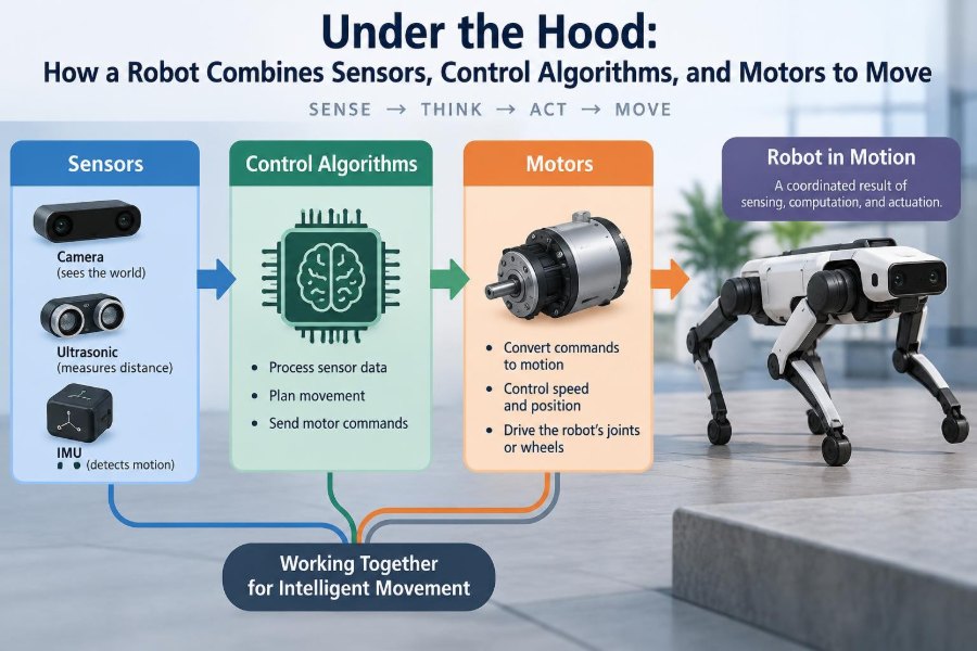
Robot movement is best understood as a repeating cycle: sense the robot and its surroundings, estimate the current state, decide on a feasible action, command actuators, and verify the result through feedback.
Sensors make the cycle aware of reality. Algorithms turn measurements and goals into decisions. Motors and transmissions create physical motion. Feedback ties all three together so the robot can respond when the real world differs from the model.
Whether the robot is a tiny line follower or a multi-axis industrial system, the principle stays the same: reliable motion comes from matching what the robot believes, what it commands, and what its mechanism can actually do.
A robot moves intelligently not because its motors are powerful, but because sensing, control, mechanics, and feedback continuously work as one system. 🦾⚙️📡