
A robot arm that easily moves an empty gripper can slow down, sag, or fault the moment someone adds a box, camera, welding torch, or inspection tool. The motor may look powerful on paper, yet the arm still cannot safely hold the load at full reach.
The missing idea is usually torque. Payload mass matters, but so does where that mass sits relative to each joint, how quickly the arm moves, and how its own links are arranged.
For students, torque calculations turn statics diagrams into a design decision. For working engineers, they are a practical check before changing end-of-arm tooling, increasing reach, or approving a new production task.
This guide builds the calculation from first principles, then adds the real-world factors that separate a useful estimate from a dependable robot-arm design.
🧭 Start With the Question Each Joint Must Answer
Torque is the turning effect of a force about an axis. At every robot joint, ask: how much twisting effort is required to hold or move everything beyond this joint?
A shoulder joint carries the forearm, wrist, tool, and payload. A wrist joint carries only the tool and payload. This is why the base-side joints are often physically larger and use higher-ratio transmissions.
🔩 Understand Torque, Force, and Moment Arm
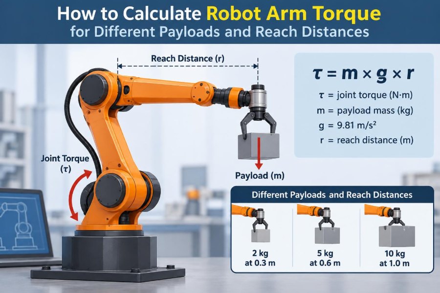
For a force acting at a right angle to a lever, the basic relationship is τ = F × r. Here, τ is torque in newton-metres (N·m), F is force in newtons, and r is perpendicular distance from the joint axis in metres.
Think of opening a door. Pushing near the hinge takes more force than pushing at the handle because the handle has a longer moment arm.
📏 Use Perpendicular Distance, Not Just Link Length
The distance in a torque calculation is the shortest perpendicular distance from the joint axis to the force’s line of action. It is not automatically the physical length of the arm.
Gravity acts vertically downward. When a horizontal arm holds a load, the horizontal reach is perpendicular to gravity and produces maximum gravity torque. When that same arm points straight down, the load’s line of action passes through the joint and gravity torque is approximately zero.
🌍 Convert Payload Mass Into Weight Force
Catalogues usually state payload in kilograms, but torque uses force. Convert mass to weight with F = m × g, where g is approximately 9.81 m/s² near Earth’s surface.
A 5 kg payload weighs about 5 × 9.81 = 49.05 N. If its centre of mass is 0.60 m horizontally from a joint, its static gravity torque at that joint is about 49.05 × 0.60 = 29.4 N·m.
🎯 Find the Payload’s True Centre of Mass
Do not use the front edge of a box or the nominal tool length unless that is actually where its mass is concentrated. The calculation needs the payload centre of mass (CoM), the balance point where its weight can be treated as acting.
A compact 5 kg steel part close to the flange creates less torque than a 5 kg long tool extending outward. This is why payload ratings alone do not fully describe a robot’s capability.
🧮 Calculate Static Payload Torque
For a simple planar arm, payload gravity torque about one joint can be written as τpayload = m × g × r × sin(θ). In this form, θ is the angle between the vector from the joint to the payload CoM and the direction of gravity.
Many teams use the easier maximum-case estimate m × g × r for a horizontal reach. It is conservative for positions that produce less gravity moment, but it does not replace checking the actual operating poses.
🦾 Include the Arm’s Own Link Weights
A joint never supports only the customer’s payload. Every link beyond that joint has mass, and each link’s weight acts through its own CoM.
For a two-link horizontal arm, shoulder gravity torque is the sum of the upper-link weight times its CoM distance, the forearm weight times its distance from the shoulder, plus tool and payload contributions. Ignoring link mass can badly underestimate torque, especially in long custom arms.
🧱 Build a Free-Body Diagram First
A free-body diagram turns a crowded mechanical assembly into forces and distances. Isolate one joint and draw every component outward from it: links, motors mounted downstream, wrist, flange, tool, cables, and payload.
- Mark each mass and its centre of mass.
- Draw gravity forces vertically downward.
- Label distances from the selected joint axis.
- Choose a positive rotation direction and keep it consistent.
This sketch often reveals omitted items before a spreadsheet hides the mistake.
➕ Sum Moments About the Joint Axis
For static holding, calculate the torque contribution of each mass and add them with signs. Components that tend to rotate the joint in opposite directions can mathematically cancel, but do not assume a counterweight is helpful in every pose.
The general static form is τjoint = Σ(mᵢ × g × rᵢ⊥). The symbol rᵢ⊥ means the perpendicular moment arm for item i.
📐 Account for Robot Pose and Joint Angle
Gravity torque changes continuously as a revolute arm rotates. A horizontal posture is commonly the worst gravity case, while a vertical posture may have little gravity moment.
Map the planned workspace rather than checking one attractive pose. A robot that is safe while loading from a low table may exceed its joint limit when it reaches sideways across the same table.
🧠 Separate Static Torque From Dynamic Torque
Static torque holds a pose against gravity. Dynamic torque accelerates or decelerates mass. A robot can pass a static holding test but still trip during a fast pick-and-place motion.
The rotational relationship is τdynamic = I × α, where I is moment of inertia about the joint axis and α is angular acceleration in radians per second squared.
⚙️ Understand Moment of Inertia
Moment of inertia is rotational resistance to acceleration. Mass farther from the axis contributes much more than the same mass close to it.
For a point-like payload, I = m × r². Notice the squared distance: doubling reach makes inertia four times larger. This is one reason long-reach robots may need reduced acceleration even when their static payload is unchanged.
🏃 Estimate Acceleration Torque for a Payload
Suppose a 5 kg payload CoM is 0.60 m from a joint. Its approximate inertia is 5 × 0.60² = 1.8 kg·m². If the joint accelerates at 4 rad/s², payload acceleration torque is 1.8 × 4 = 7.2 N·m.
That dynamic torque adds to gravity torque when acceleration acts against gravity. During motion in the other direction, gravity may assist acceleration but will oppose braking. Evaluate both acceleration and deceleration cases.
📚 Use Proper Inertia Models for Links
A real link is not a point mass. A uniform slender rod rotating about one end has inertia I = (1/3)mL², while the same rod about its centre has I = (1/12)mL².
Complex parts can be approximated with several simple shapes, taken from CAD mass properties, or measured experimentally. CAD values are useful only if the model includes realistic materials, fasteners, motors, and attached hardware.
🔄 Apply the Parallel-Axis Theorem
When a component’s known inertia is about its own CoM but the joint axis is elsewhere, use Ijoint = ICoM + m × d². The distance d is between parallel axes.
This theorem is essential for arms because a forearm’s inertia about the elbow is different from its inertia about the shoulder. It also explains why mounting a motor farther out can impose a large upstream penalty.
🧷 Include Tooling, Cables, and Attached Equipment
End-of-arm tooling includes more than the gripper body. Add fingers, adapters, hoses, valves, cameras, protective covers, cable dress packs, and any carried fixture.
Flexible cables are awkward because their shape changes with pose. For an early design, use a conservative effective mass and reach. Validate later with the actual routing, because a cable can create drag, snagging, or intermittent extra load beyond its simple weight.
🧲 Consider Counterbalances Carefully
Springs, gas struts, counterweights, and constant-force mechanisms can reduce gravity torque, allowing smaller actuators or lower continuous power. They are especially useful for arms that repeat a limited range of vertical motion.
They are not free torque. A counterweight increases total inertia, and springs produce torque that changes with position. The mechanism must be checked through the full range, including maintenance positions and fault recovery.
🛞 Convert Joint Torque to Motor Torque
Motors often drive joints through a gearbox, belt, chain, harmonic drive, or cycloidal reducer. With a reduction ratio N, ideal motor torque is approximately joint torque divided by N.
Transmission efficiency matters: τmotor ≈ τjoint / (N × η). Use the appropriate efficiency for the direction and operating condition. Gear friction, preload, and backdrivability can make low-speed behavior less ideal than this simplified equation.
🔥 Compare Continuous and Peak Torque Ratings
A motor’s continuous torque is limited by heating over sustained operation. Peak torque may be available only briefly for acceleration, collision recovery, or short high-load intervals.
Holding a horizontal load is often a continuous requirement, while a fast move may use peak torque. Check the motion duty cycle, ambient temperature, cooling arrangement, and controller current limits—not only a single maximum number on a datasheet.
🛡️ Choose a Safety Margin With a Reason
After estimating required torque, apply a design margin for uncertainty, variations in payload, friction, manufacturing tolerances, trajectory changes, and model error. The appropriate margin depends on how well known the application is and what failure would mean.
An oversized margin can raise cost, mass, inertia, and energy use. An undersized one can produce overheating, poor tracking, gearbox wear, or a dropped load. Margin is not a substitute for identifying an omitted mass or an impossible acceleration profile.
📊 Work Through a Two-Link Example
Consider a hypothetical planar arm held horizontal. Link 1 is 0.40 m long and 3 kg, with CoM 0.20 m from the shoulder. Link 2 is 0.35 m long and 2 kg, with CoM 0.175 m from the elbow. A 1 kg tool has its CoM 0.42 m from the shoulder, and a 4 kg payload has its CoM 0.65 m from the shoulder.
At the shoulder, approximate static gravity torque is:
Link 1: 3 × 9.81 × 0.20 = 5.89 N·m
Link 2: 2 × 9.81 × (0.40 + 0.175) = 11.28 N·m
Tool:   1 × 9.81 × 0.42 = 4.12 N·m
Payload:4 × 9.81 × 0.65 = 25.51 N·m
Total shoulder torque ≈ 46.8 N·m
At the elbow, only link 2, tool, and payload beyond the elbow contribute. The payload’s lever arm from the elbow is 0.65 − 0.40 = 0.25 m, assuming this straight horizontal pose. Recalculate each joint independently rather than copying the shoulder result.
📋 Keep Units Consistent
Most preventable torque errors are unit errors. Convert millimetres to metres, grams to kilograms, degrees to radians for angular acceleration calculations, and kilogram-force centimetres to N·m when comparing older component specifications.
| Quantity | Preferred SI unit | Common trap |
|---|---|---|
| Mass | kg | Using kg directly as force |
| Distance | m | Entering mm without conversion |
| Torque | N·m | Confusing N·m with joules |
| Angular acceleration | rad/s² | Using degrees/s² directly |
🧪 Validate Calculations With Measurement
Calculations are models, not proof. During controlled commissioning, observe motor current, position tracking, temperature, vibration, and fault behavior across representative payloads and trajectories.
A torque sensor can directly measure loads in some setups, but it is not always necessary. Motor current can be informative when the motor torque constant, drive behavior, and friction are understood; it should not be treated as a perfectly direct torque reading.
🗺️ Check the Entire Motion Envelope
The worst case may occur at a pose you would not guess: full lateral reach, a high-speed reversal, a stretched configuration with a heavy wrist angle, or a recovery move after a pause.
Build a grid of joint angles and planned accelerations, or simulate the motion in robotics software. Record maximum required torque at each joint, then compare it against position-dependent limits, especially where a mechanism approaches singular or poorly supported configurations.
⚠️ Avoid Common Torque Calculation Mistakes
- Using total reach instead of the actual CoM location.
- Checking payload weight but omitting link, wrist, and tooling masses.
- Using only static gravity torque for a fast trajectory.
- Comparing joint torque directly with motor torque before gearbox ratio and efficiency.
- Choosing from peak torque while the task requires continuous holding.
- Assuming a catalogue payload rating applies at every reach, orientation, and speed.
These errors often compound. A small error in distance becomes particularly costly when it also affects inertia and acceleration torque.
🏷️ Read Robot Payload Ratings Critically
An industrial robot’s stated payload is useful, but it normally comes with conditions. Manufacturers may specify allowable wrist moments, inertia limits, centre-of-mass offsets, speed limits, and a defined mounting orientation.
A 10 kg rating does not necessarily mean any 10 kg object can be held at any extension with any long tool. Use the manufacturer’s load diagrams and motion limits for the exact robot model; treat a hand calculation as an independent engineering check, not a replacement for those limits.
🧰 Build a Reusable Calculation Worksheet
A clear worksheet makes design reviews faster and exposes changed assumptions. Create rows for every body and columns for mass, CoM coordinates, inertia, gravity torque, acceleration torque, transmission ratio, efficiency, and safety factor.
Keep assumptions beside the results: pose, payload range, acceleration, cycle time, orientation, and whether the result is continuous or peak. Version-controlled CAD properties and spreadsheets help prevent a tooling change from silently invalidating an earlier calculation.
💻 Use CAD and Simulation Without Blind Trust
CAD can report mass properties quickly, while multibody simulation can calculate torque through a full path. These tools are valuable when several joints move at once, because link accelerations and orientations are coupled.
But software only reflects inputs. Confirm coordinate frames, joint axes, material assignments, gear ratios, gravity direction, contact assumptions, and whether motors or cable masses are included. A polished plot can still be based on the wrong centre of mass.
🚧 Connect Torque Design to Safety
Insufficient torque is not merely a productivity issue. It can cause drooping, missed placement, unexpected stopping, overheating, or inadequate braking control. Excessive torque capacity also requires thought, because a stronger actuator can increase collision forces if safeguards are poorly designed.
Use appropriate guarding, load retention, limits, emergency-stop behavior, and risk assessment for the application. Torque sizing supports safe operation, but it does not by itself establish that a robot system is safe.
✅ The Core Principle: Mass Times Reach Is Only the Beginning
The fastest first estimate is payload mass times gravity times perpendicular reach. A reliable design then adds the arm’s own mass, true centres of mass, pose-dependent geometry, acceleration inertia, drivetrain losses, thermal limits, and a justified margin.
Calculate each joint from the outside inward, evaluate the full intended motion, and verify the model on the real machine. That workflow scales from a classroom two-link arm to a production manipulator with complex tooling.
A robot arm’s torque requirement is determined not just by what it carries, but by where that mass sits, how the arm is oriented, and how the motion is performed. Treat those three questions as one engineering problem, and your actuator choices will be far more defensible. 🦾⚙️📐