
A warehouse robot rolls toward a pallet that has been left slightly out of place. A delivery rover meets a sunlit curb. A small indoor robot approaches a glass door. In each case, the robot has the same basic question: what is around me, and can I move safely?
That question sounds simple until the environment becomes messy. Bright sunlight can wash out an image. A soft curtain may absorb sound. Rain can scatter laser light. A shiny metal surface can create a confusing reflection. The sensor that works beautifully in one scene may become unreliable in another.
Choosing perception hardware is therefore not a contest to find the “best” sensor. It is an engineering decision about what the robot must detect, how fast it moves, where it operates, what failures are acceptable, and how much computing power it can carry.
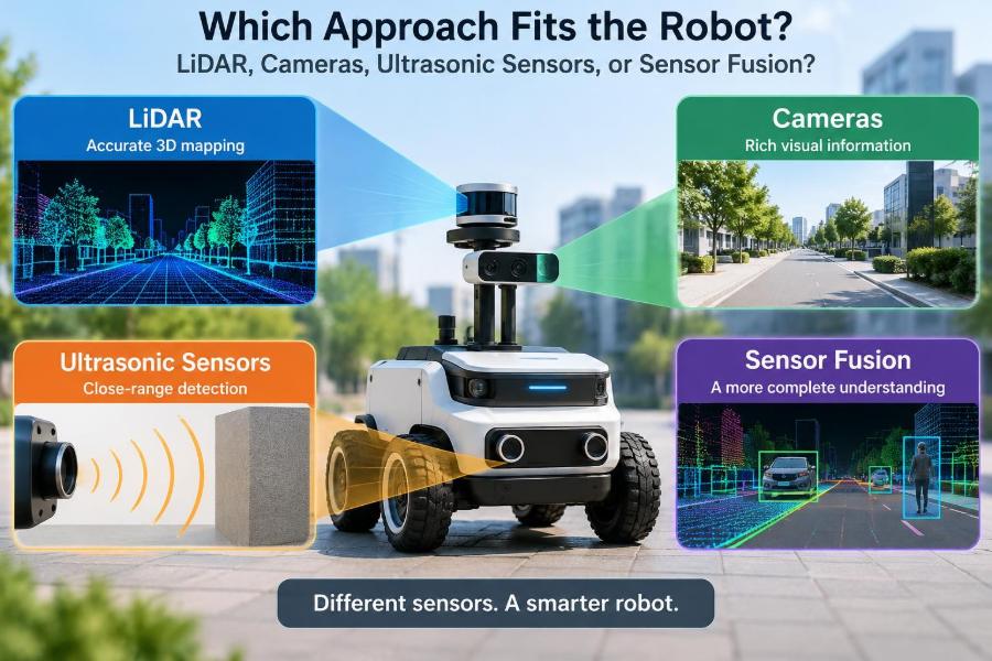
LiDAR, cameras, ultrasonic sensors, and sensor fusion each solve different parts of the perception problem. Understanding their trade-offs helps you design robots that behave predictably outside a controlled demo.
🧭 Start With the Robot’s Actual Job
Begin with the task, not the sensor catalog. A robot that only needs to stop before hitting a wall has a very different perception requirement from an autonomous vehicle that must identify lanes, pedestrians, traffic lights, and distant obstacles.
Write down the decisions the robot must make. Common examples include obstacle avoidance, object recognition, localization, mapping, docking, edge detection, and free-space estimation.
A sensor is appropriate only if its information supports a required decision with enough reliability and enough time to act. This framing prevents expensive hardware from being added simply because it is technically impressive.
👁️ What Robot Perception Really Means
Perception is the process of turning raw measurements into a useful model of the robot’s surroundings. A distance reading, a pixel array, or a laser point cloud is not yet understanding; software must interpret it.
That interpretation may be simple, such as “something is closer than 20 centimeters.” It may also be complex, such as “this is a person walking toward a crosswalk, likely to enter the path.”
The path from sensing to action usually includes measurement, filtering, detection, tracking, planning, and control. Weakness at any stage can make a capable sensor appear ineffective.
📏 LiDAR Measures Shape Through Light
LiDAR, short for light detection and ranging, estimates distance by emitting laser light and measuring the returning signal. Scanning systems build a collection of range measurements called a point cloud.
A two-dimensional LiDAR typically reports distances across a horizontal plane. A three-dimensional unit samples a volume, making it more useful for objects that extend above or below a single scan line.
For many robotics tasks, LiDAR’s great advantage is direct geometry. It can show where surfaces appear to be without first needing to infer depth from visual texture.
🎯 Where LiDAR Is Especially Strong
LiDAR is often a strong fit when a robot needs accurate obstacle boundaries, repeatable range data, or geometric maps. Mobile robots commonly use planar LiDAR for indoor navigation because walls, rack legs, and many furniture edges produce useful scan returns.
It can also support scan matching: comparing the current scan with a map or earlier scans to estimate motion. This is useful when satellite positioning is unavailable, such as in warehouses, tunnels, or large indoor facilities.
LiDAR does not inherently tell the robot what an object is. It can show a cluster at a location, but distinguishing a cardboard box from a person usually requires additional reasoning or another sensor.
🌫️ LiDAR’s Environmental Limits
Laser ranging is not immune to the world. Fog, dust, rain, snow, and airborne particles can scatter light and create returns that do not represent solid obstacles. Reflective, transparent, very dark, or angled surfaces may also produce weak, shifted, or missing measurements.
A single scan plane can miss hazards. For example, a low pallet fork might fall below the scan height, while a tabletop might sit above it. Mounting height is therefore a safety and coverage decision, not merely a packaging detail.
LiDAR performance should be tested with the materials and lighting found at the deployment site. A clean lab corridor cannot expose every operational failure mode.
📷 Cameras Capture Rich Visual Meaning
Cameras measure light arranged into images. Their primary strength is semantic information: color, markings, text, gestures, object appearance, and scene context.
A camera can help a robot recognize a charging dock by its visual pattern, read a barcode, detect a pedestrian, follow a painted line, or distinguish a stop sign from a red storage bin. These are tasks where shape alone may not be enough.
Modern machine-learning models can extract powerful features from images, but they remain dependent on training data, camera quality, and the similarity between training conditions and the real environment.
🧠 Recognition Is Not the Same as Distance
A conventional single camera provides a two-dimensional image. A large object nearby and a small object far away can occupy similar pixel areas, so distance is not directly measured from one image alone.
Software can estimate depth using known object sizes, perspective, motion, or learned models. These estimates can be useful, but their uncertainty should be treated differently from a direct range measurement.
Stereo camera systems use two viewpoints and triangulation to estimate depth. Their performance depends on calibration and on finding matching image features, which can be difficult on plain walls, repetitive patterns, dark surfaces, or low-texture objects.
☀️ Cameras Depend on Illumination
A camera sees reflected or emitted light, so lighting is part of the sensing system. Direct sun, glare, shadows, low light, flickering artificial lamps, and rapid transitions between indoors and outdoors can all alter the image.
Automatic exposure can help, but it may introduce trade-offs. Brightening a dark foreground can saturate a sunlit background; shortening exposure to reduce motion blur can make an indoor image noisy.
Useful mitigation includes controlled illumination, high dynamic range imaging, protective lens design, and testing at the times of day when the robot will actually operate. None of these removes the need to define safe fallback behavior.
⚙️ Camera Compute and Latency Matter
Images contain a large amount of data. Detecting and classifying objects may require substantial compute, especially when models must run at high frame rates or process multiple camera streams.
Latency is the delay from photons reaching the sensor to a control decision being issued. If a robot moves quickly, even a good detector can be unsafe if its output is stale by the time braking begins.
Engineers should measure end-to-end latency, not just a model’s inference time. Image capture, transfer, preprocessing, scheduling, object tracking, planning, and actuator response all contribute.
📡 Ultrasonic Sensors Use Sound Echoes
Ultrasonic sensors emit high-frequency sound and estimate distance from the returning echo. They are familiar from parking assistance systems and are widely used for short-range obstacle detection on robots.
The hardware is generally compact, inexpensive, and straightforward to interface. For a slow indoor platform, a ring of ultrasonic sensors can provide practical close-range awareness where a camera may struggle to estimate exact distance.
They are best understood as proximity sensors with a coverage region, rather than as detailed imagers of the world.
🔊 Beam Width Shapes Ultrasonic Readings
Ultrasonic sound spreads in a cone. A reported distance may correspond to any reflecting surface within that cone, not necessarily the object directly in front of the sensor.
This can create ambiguity near corners, narrow posts, or cluttered shelves. A sensor may report the closest strong echo while hiding the layout of other nearby objects.
Mounting angle, sensor spacing, and robot speed should reflect this behavior. Overlapping fields can reduce blind areas, but too many sensors operating simultaneously can create acoustic interference.
🧽 Materials and Air Affect Ultrasound
Soft fabrics, foam, and irregular surfaces can absorb or scatter acoustic energy. Smooth angled surfaces may direct sound away from the receiver. Temperature and air conditions also influence sound speed, which can affect distance estimates.
These effects do not make ultrasonic sensing unusable; they define where it needs conservative engineering. It works well as one layer in a low-speed collision-avoidance system when its uncertainties are accounted for.
A robot should not assume that “no echo” proves “no obstacle.” A missed echo can be an unknown condition that warrants slower motion or corroboration from another sensor.
🗺️ Compare the Sensors by Information, Not Hype
| Approach | Primary information | Typical strength | Common limitation |
|---|---|---|---|
| LiDAR | Range and geometry | Mapping and obstacle shape | Limited semantic identity; surface and weather effects |
| Camera | Appearance and context | Recognition, markings, and inspection | Lighting sensitivity and indirect depth for monocular systems |
| Ultrasonic | Short-range echo distance | Low-cost proximity sensing | Broad beam and material-dependent echoes |
| Sensor fusion | Combined estimates | Complementary coverage and fault awareness | Calibration, timing, and software complexity |
This comparison is deliberately broad. Exact performance varies widely by sensor model, mounting, target material, environment, and signal-processing choices.
🧩 Sensor Fusion Combines Complementary Evidence
Sensor fusion combines measurements from multiple sources to estimate something more useful than any single source can provide alone. A camera might classify an object as a person while LiDAR provides its position and shape.
Fusion can happen at different levels. Early fusion combines raw or lightly processed data; later fusion combines outputs such as object tracks, occupancy maps, or independent hazard flags.
Fusion is valuable when sensors fail differently. Combining two sensors with the same blind spot does not create meaningful robustness.
🧷 Redundancy and Diversity Are Different
Redundancy means having multiple ways to obtain a needed function. Diversity means those ways use different physical principles or different failure pathways.
Two cameras provide redundancy for visual coverage, but both may be impaired by severe glare. A camera and LiDAR are more diverse because one depends primarily on image appearance while the other measures reflected laser returns.
For safety-relevant behavior, diversity can be more valuable than simply adding more units of the same sensor. The correct arrangement still depends on the hazard analysis and system requirements.
⏱️ Time Synchronization Is a Hidden Requirement
Fusion assumes measurements refer to nearly the same world state. If a camera image is delayed while LiDAR data is current, a moving person may appear in different locations across the two data streams.
Accurate timestamps, known transport delays, and a common clock are essential. Systems may compensate by predicting object motion, but prediction itself has uncertainty.
Synchronization becomes more demanding as robot speed, sensor spacing, and environmental motion increase. A slow inspection robot can tolerate errors that would be unacceptable on a fast mobile platform.
📐 Extrinsic Calibration Connects Sensor Frames
Every sensor has a coordinate frame: its own reference orientation and position. Extrinsic calibration estimates how those frames relate to the robot body and to one another.
If a camera is believed to be a few degrees from its actual orientation, projected LiDAR points may land on the wrong image region. The resulting fusion can look convincing while producing incorrect object locations.
Calibration should be verified after installation, repair, vibration exposure, or mechanical changes. Good calibration also needs a stable physical mount; software cannot permanently compensate for a sensor bracket that shifts in operation.
🧪 Test the Failure Cases, Not Just Normal Cases
A perception system often looks excellent in clean, expected conditions. The more informative tests are the awkward ones: a black cart in a dim aisle, clear plastic at a doorway, a low overhang, a wet floor reflection, or two obstacles close together.
Build scenarios from the robot’s operating domain and from known sensor physics. Test degraded sensors too: a dirty lens, partially blocked LiDAR window, disconnected ultrasonic unit, or dropped camera frames.
Document what the robot does when confidence is low. Slowing down, stopping, requesting help, or switching to a restricted mode can be safer than forcing a classification.
🏭 Indoor Warehouse Robots Need Geometry and Coverage
Warehouse environments often reward reliable range sensing because the robot must navigate around racks, pallets, carts, and people. Planar LiDAR can be effective for localization and path clearance, while cameras add value for barcode reading, pallet identification, and recognizing visual work zones.
Ultrasonic sensors can serve as short-range protection around bump-prone areas, particularly near docking stations or at corners where scan coverage is weak.
A practical design might use LiDAR for navigation, cameras for task-specific recognition, wheel encoders and an inertial measurement unit for motion estimation, and close-range sensors for protective behavior. This is an example architecture, not a universal recipe.
🚗 Outdoor Robots Face a Harder Sensory World
Outdoor robots must handle changing illumination, vegetation, uneven ground, weather, larger distances, and more varied objects. Cameras offer crucial semantic cues, while three-dimensional range data can support terrain and obstacle reasoning.
However, outdoor fusion must address weather contamination, sensor heating, lens cleanliness, and the fact that maps can change. A parked truck, construction barrier, or pile of leaves may not match a prior map.
When people share the space, the system should be designed around conservative behavior under uncertainty. Perception is only one part of safe operation; braking capability, speed limits, route design, and supervision matter too.
🧹 Simple Household Robots Can Stay Simple
A floor-cleaning robot does not necessarily need a premium 3D perception stack. If it moves slowly and its task is primarily coverage, bump sensing, cliff sensing, short-range ranging, and simple mapping may be sufficient.
A camera can improve room recognition or obstacle avoidance, but it also introduces privacy, lighting, and compute considerations. LiDAR may improve mapping and navigation in many homes, yet furniture layouts and dangling fabrics still require thoughtful coverage.
The goal is proportionality. Complexity should solve a real operational problem rather than create more calibration and maintenance work.
🦿 Manipulators Need Near-Field Perception
Robot arms often need to locate, grasp, and inspect objects at close range. Cameras can provide object identity, pose cues, and quality-inspection detail; depth cameras or LiDAR-like ranging technologies can help estimate surfaces and grasp geometry.
Ultrasonic sensors are less common for precise grasp planning because of their broad spatial response, but they may be useful for coarse proximity sensing in constrained applications.
For manipulation, consider occlusion carefully. The robot’s own gripper may hide the target during approach, so wrist-mounted sensors or multiple viewpoints can be more valuable than a single distant camera.
🛑 Safety Functions Need Conservative Design
Do not treat a perception demo as proof of a safety function. A system that identifies obstacles most of the time may still be unsuitable as the only barrier against injury or damage.
Safety-related designs require hazard analysis, defined operating limits, verification, validation, and appropriate safeguards. Depending on the application, these can include physical guards, emergency stops, speed restrictions, monitored zones, and independent protective sensing.
Follow applicable regulations, standards, and site-specific requirements with qualified safety professionals. The needed approach varies by robot type, workplace, jurisdiction, and potential harm.
💻 Perception Software Defines the Usable Sensor
Hardware specifications describe potential, not guaranteed system behavior. Filtering can remove noise but may erase thin obstacles. Object detectors can recognize familiar classes but may misclassify unfamiliar objects. Mapping algorithms can drift when features are scarce.
Choose software that exposes confidence, health status, and clear failure behavior. A binary “object/no object” output may be insufficient when the planner needs to know whether an area is observed, blocked, or unknown.
Log sensor data and decisions during testing. Replaying recorded scenarios is one of the most practical ways to debug perception changes without repeatedly recreating every physical scene.
🔋 Power, Heat, and Packaging Are Design Constraints
High-resolution cameras, active LiDAR units, and onboard accelerators consume power and generate heat. Their placement can affect battery life, enclosure design, cooling, and maintenance access.
A sensor behind a dirty protective cover is a different sensor from the one tested on a bench. Window material, optical distortion, condensation, vibration isolation, cable routing, and cleaning procedures all affect deployed performance.
Include these physical constraints early. Retrofitting cooling or relocating a sensor after the mechanical design is fixed can be far more difficult than making room during concept development.
💰 Evaluate Total Cost, Not Purchase Price
A low-cost sensor can become expensive if it requires extensive compute, difficult calibration, frequent replacement, or large amounts of engineering time to manage edge cases. Conversely, a higher-cost range sensor may simplify navigation software enough to justify its cost in a specific product.
Estimate the complete system cost: sensor hardware, compute, mounts, protective housing, wiring, calibration tools, data collection, model development, testing, maintenance, and field support.
The right business decision depends on production scale and risk. A research prototype may prioritize flexibility, while a fleet product may prioritize supply stability, serviceability, and repeatable calibration.
🔍 A Practical Selection Workflow
- Define the robot’s tasks, operating area, speed, and stopping needs.
- List the objects, surfaces, lighting, weather, and clutter it must handle.
- Translate those conditions into information needs: range, identity, pose, free space, or localization.
- Identify failure cases and decide what the robot should do when information is uncertain.
- Prototype candidate sensors in representative conditions, including degraded cases.
- Measure accuracy, coverage, latency, compute load, and recovery behavior at the system level.
- Select the simplest architecture that meets the requirements with an appropriate margin.
This workflow makes trade-offs visible early, before a team becomes committed to a sensor because of an impressive initial demonstration.
⚠️ Common Selection Mistakes
- Choosing by specification sheet alone: laboratory range or resolution does not describe every target material and environment.
- Ignoring mounting geometry: blind spots, self-occlusion, and vibration can defeat otherwise good hardware.
- Assuming fusion automatically fixes errors: poorly timed or miscalibrated data can make estimates worse.
- Testing only known objects: operational environments contain unexpected shapes, surfaces, and behaviors.
- Hiding uncertainty from the planner: a robot must distinguish clear space from unobserved space.
Most of these mistakes are process problems rather than sensor problems. They can be reduced by connecting perception tests directly to real robot decisions.
📊 Define Metrics That Match the Mission
“Accuracy” is too vague on its own. A docking robot may care about final pose error. An obstacle-avoidance system may care about detection distance, false alarms, and stopping margin. A vision inspection cell may care about defect detection under production lighting.
Measure metrics across meaningful conditions, then examine worst-case behavior as well as averages. A high average score can hide rare but consequential failures.
Also measure availability: how often is each sensor producing trustworthy data? A system that reports its degraded state can make safer decisions than one that silently outputs plausible but unreliable values.
🔧 Maintain Sensors as Part of Operations
Perception changes over time. Lenses collect dust, windows scratch, mounts loosen, connectors corrode, and calibration can drift. A robot that passed commissioning may gradually develop blind areas without a maintenance plan.
Design diagnostics that detect blocked views, impossible readings, dropped data, overheating, and disagreement between sensors. Schedule inspection and cleaning according to the environment rather than assuming a fixed interval works everywhere.
Field logs should feed back into design. Repeated false stops near a particular surface or lighting condition are clues that the sensing architecture, mounting, or decision policy needs adjustment.
🧠 The Core Principle: Match Evidence to Uncertainty
LiDAR is compelling when geometry and range are central. Cameras are compelling when meaning, appearance, and visual detail matter. Ultrasonic sensors are compelling for economical short-range awareness. Fusion is compelling when complementary evidence addresses meaningful failure modes.
None of these choices is automatically superior. A well-designed single-sensor solution can outperform a poorly integrated multi-sensor system, while a demanding environment may genuinely require several sensing modalities.
The best perception stack is the one that provides the right evidence, at the right time, with known limits and safe behavior when that evidence becomes uncertain.
Build from the robot’s mission, test the conditions it will actually meet, and let measurable failure modes—not marketing labels—guide the final choice. 🦾📷📡