
A person can pick up a paper cup of coffee, a ripe tomato, or a heavy toolbox without consciously calculating the exact force required. Their hands feel resistance, weight, slipping, and contact almost instantly, then make tiny corrections.
Robots do not begin with that ability. A motor can move a gripper to a precise position, but position alone cannot reveal whether the gripper has touched an object, is crushing it, or is barely holding it.
This gap matters wherever robots share physical tasks with people: packing groceries, inserting electronic connectors, polishing parts, assisting in surgery, or handling fragile laboratory samples. A robot needs more than vision and motion planning. It needs a sense of touch.
Force-torque sensors provide much of that sense. By measuring pushes, pulls, and twisting loads, they let machines react to the physical world rather than treating it as a perfectly predictable diagram.
🧭 What a Force-Torque Sensor Measures
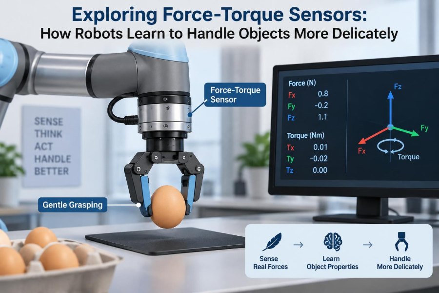
A force-torque sensor is a device that measures loads applied to it. In robotics, it is commonly mounted between a robot arm and its tool, or inside a gripper wrist.
Force describes a straight push or pull. Torque describes a turning effect around an axis, such as the twist created when a screwdriver turns a screw or when a gripper holds an object off-center.
These measurements give a controller feedback about interaction. Instead of merely commanding, “move downward 10 millimeters,” it can command, “move downward until gentle contact is detected, then maintain a safe pressing force.”
📐 Understanding the Six Axes
Many industrial sensors measure six degrees of force and torque: forces along the X, Y, and Z axes, plus torques about those same axes. Together, these values describe a remarkably complete picture of a load at the sensor.
| Measurement | What it describes | Simple example |
|---|---|---|
| Fx, Fy, Fz | Linear push or pull | A gripper pressing against a surface |
| Tx, Ty, Tz | Rotational loading | A tool twisting while tightening a fastener |
The coordinate directions depend on how the sensor is installed. Engineers must define a sensor frame and relate it correctly to the robot’s tool frame; otherwise, a force that appears “downward” physically may be interpreted as sideways by software.
✋ Why Position Control Alone Falls Short
Traditional robot programming often relies on position control: the robot is told where its joints or tool should be. That works well when parts, fixtures, and paths are highly repeatable.
Real environments contain variation. A tray may sit slightly higher than expected, a part may be misaligned, or a flexible cable may bend differently on every cycle. If the robot insists on reaching an exact position, it can jam, damage the part, or apply excessive load.
Force feedback adds a second source of information. Position says where the robot believes it is; force says what the robot is physically encountering.
🧠 The Human Touch Analogy
Consider inserting a key into a lock. You use vision to find the keyhole, but touch guides the final action. Resistance tells you whether the key is aligned; a small change in pressure or angle often solves the problem.
A force-controlled robot behaves similarly. It can make small exploratory motions, observe changing forces and torques, and adjust its motion rather than forcing a rigid trajectory.
The analogy has limits. Human touch includes skin deformation, temperature, texture, and rich biological processing. A wrist sensor measures loads, not every property of touch. Still, it supplies a useful mechanical awareness.
⚙️ How Strain Gauges Turn Load Into Data
Many force-torque sensors use strain gauges, thin electrical elements bonded to a carefully designed metal structure. When a load flexes that structure by a tiny amount, the electrical resistance of the gauges changes.
The sensor electronics detect these very small changes, often by arranging gauges in a Wheatstone bridge circuit. Calibration then converts electrical signals into force and torque values.
The metal body is intentionally stiff enough for accurate work, yet compliant enough to deform measurably under its rated load. This balance is central to sensor design: too flexible and it may vibrate or overload easily; too stiff and sensitivity suffers.
🔄 Other Ways to Sense Contact
Force-torque sensors are not the only contact sensors in robotics. Their value becomes clearer when compared with nearby technologies.
- Motor-current estimation infers load from motor current. It is inexpensive but can be distorted by friction, gear backlash, and changing dynamics.
- Tactile arrays on fingertips can reveal local contact patterns, pressure distribution, and sometimes slip. They are especially useful for dexterous hands.
- Joint torque sensors measure loading nearer to individual joints, supporting compliant whole-arm behavior.
- Vision systems can identify pose and motion but cannot reliably determine contact force by themselves.
These approaches are often complementary. A robot might use cameras for approach, a wrist sensor for contact-rich insertion, and fingertip sensors to verify the grip.
📍 Where Sensors Are Mounted
The classic location is at the robot wrist, between the final arm flange and the end effector. This placement measures forces transmitted through the tool and works with many gripper, screwdriver, polishing, and inspection configurations.
Mounting farther from the contact point has consequences. The tool’s own weight, cable forces, and inertial loads all appear in the measurement, so the controller must compensate for them.
Some applications instead place sensors beneath a workpiece, within a gripper finger, or under a fixture. The best location depends on the question the system needs answered: “What is the tool experiencing?” is not always the same as “What is happening at this one contact point?”
🧲 Gravity Compensation and Tool Weight
A wrist sensor continuously feels the mass of the end effector. As the arm rotates, gravity projects differently onto the sensor axes, even when the tool is not touching anything.
Without gravity compensation, the controller might mistake tool weight for contact force. A gripper could stop early while descending, or a polishing robot could apply inconsistent pressure at different orientations.
Compensation requires an estimate of the tool’s mass and center of mass. In practice, engineers may identify these values through a calibration procedure, then transform the expected gravitational load as the robot pose changes.
🌊 Dynamic Loads Can Look Like Contact
Acceleration also produces inertial forces. A heavy tool moved quickly may generate large readings even in free space, and abrupt stops can create short peaks that resemble impacts.
This means force data must be interpreted in context. A reading occurring during a rapid acceleration is not automatically evidence that the robot hit an object.
Careful systems combine robot velocity, acceleration, and pose with sensor data. They also avoid commanding unnecessary jerks, because smooth motion reduces both mechanical stress and measurement ambiguity.
🎯 Calibration Gives Numbers Meaning
A sensor output is only useful if its axes, scale factors, and cross-axis effects are understood. Calibration establishes the relationship between known applied loads and reported measurements.
For example, a pure downward load may produce a small response in more than one channel because no physical structure is perfectly isolated. Calibration matrices help correct this coupling.
Users should follow the manufacturer’s calibration guidance and preserve traceability when an application requires it. A sensor that is overloaded, mechanically modified, or exposed to unusual conditions may need to be checked again before precision work resumes.
🧼 Zeroing Is Not the Same as Calibration
Zeroing sets the current unloaded reading as the baseline. It is often done after the robot has attached its tool and moved to a condition where no external contact is present.
Calibration, by contrast, determines how raw signals map to physical loads. Zeroing can remove a small offset; it cannot repair an incorrect sensitivity value or a damaged sensing element.
Confusing the two can hide a problem. If a sensor requires large or frequent zero adjustments, engineers should investigate temperature changes, cable strain, mounting stresses, or unintended contact.
🧊 Noise, Drift, and Filtering
All real sensors contain noise: small fluctuations caused by electronics, vibration, quantization, and environmental effects. A controller that responds to every tiny fluctuation may chatter or repeatedly change direction.
Filtering can make readings more stable. A low-pass filter, for instance, suppresses rapid changes above a chosen frequency. However, aggressive filtering also adds delay and can conceal a real impact.
The practical goal is not the smoothest possible graph. It is a signal that is stable enough for the task and fast enough to support a safe, effective response.
📊 Sampling Rate and Control Timing
Contact changes can occur quickly, particularly during insertion, tapping, deburring, or collision detection. Sensor measurements, communication, robot control, and software decisions must all arrive quickly enough to be useful.
A fast sensor connected through a slow processing pipeline does not create fast force control. Timing should be evaluated end to end, including filtering and the robot’s ability to change its motion.
For gentle, slow assembly, modest update rates may be sufficient. For high-speed contact tasks, latency and synchronization become more demanding engineering constraints.
🤝 Force Control Versus Compliance Control
Force control aims to regulate a measured force to a target value. A sanding robot, for example, may adjust its normal motion to maintain approximately constant contact force as a surface varies.
Compliance control makes the robot yield in selected directions. It may not target one exact force; instead, it lets contact deflect the tool in a controlled, spring-like way.
Both approaches can make robots gentler. The right choice depends on the task: sustained pressing often benefits from force regulation, while uncertain alignment often benefits from intentional compliance.
🪀 Impedance and Admittance in Plain Language
Two common control concepts describe how motion and force are related. In impedance control, the robot behaves as though it has chosen stiffness, damping, and inertia, resisting displacement in a controlled manner.
In admittance control, measured force is used to generate a motion adjustment. This can be useful when a robot’s lower-level motion controller accepts position commands but does not directly support torque control.
Think of impedance as choosing how a virtual spring responds when pushed. Think of admittance as observing a push and deciding how far the robot should move away or along with it.
🧩 Delicate Picking Starts Before Contact
Handling an object gently is not only about the final gripping force. A reliable sequence begins with perception and approach planning.
- Estimate the object’s location, orientation, and accessible grasp regions.
- Approach at a suitable speed while leaving room for uncertainty.
- Detect first contact using force, tactile sensing, or gripper position changes.
- Close the gripper gradually and confirm that the object is retained.
- Lift with motion limits appropriate to the object’s mass and fragility.
A force-torque sensor is especially helpful during contact and lifting, where an unexpected load can expose a misgrasp, obstruction, or collision.
🍓 Example: Picking a Fragile Food Item
Imagine a hypothetical produce-packing cell picking soft fruit. Camera data may identify a fruit and guide the gripper near it, but fruit size, ripeness, and exact resting position can vary.
A compliant approach can stop when light contact is detected. The gripper can then close only enough to support the item, while the wrist sensor checks whether the load during lifting is consistent with a successful pickup.
Force sensing does not guarantee that every fruit is undamaged. Gripper material, finger shape, acceleration limits, and object-specific testing remain essential. The sensor simply gives the system feedback it otherwise lacks.
🔩 Example: Inserting a Connector
Electronic connectors are easy to damage when misaligned. A purely position-driven robot may press harder when a connector catches on an edge, bending pins or damaging the housing.
With force-torque feedback, the robot can detect sideways forces or twisting moments that suggest poor alignment. It can back away, search with small controlled motions, or request a new vision estimate rather than continuing to push.
This is often called force-guided insertion. It is valuable because the final alignment tolerance may be smaller than uncertainty in fixtures, parts, or robot positioning.
🪛 Example: Fastening and Tool Use
When driving a screw, axial force keeps the bit engaged while torque reveals resistance to turning. Too little downward force can cause cam-out; excessive force can damage delicate materials or tools.
A tool-mounted sensor can help monitor the contact load and detect unusual side forces. It cannot by itself determine every fastening quality issue, but it provides signals that can complement spindle torque, angle, and vision data.
The same principle applies to scraping, polishing, cutting, and dispensing tasks: process quality often depends on the interaction force, not only on the path.
🦾 Collision Detection and Safer Interaction
Unexpected force can indicate that a robot has contacted an obstacle, fixture, or person. A force-torque sensor can therefore contribute to collision detection and responsive stopping behavior.
It should not be treated as a complete safety system on its own. Detection thresholds, reaction time, robot speed, tool geometry, risk assessment, guarding, and applicable safety requirements all affect whether an installation is acceptably safe.
In collaborative applications, low commanded forces and compliant behavior can improve interaction quality. Yet a slowly moving robot with a sharp tool may still present hazards, while a fast robot can create high forces before any controller reacts.
📏 Choosing the Right Measurement Range
Every sensor has a rated force and torque range. Selecting an excessively large range can reduce useful resolution for delicate work, while selecting too small a range risks saturation or permanent damage.
Engineers should estimate expected loads from the tool, object, process, acceleration, and worst credible fault conditions. Off-center tools deserve particular attention because even a moderate force can create a substantial moment at the sensor.
A reasonable selection leaves margin for normal variation without making the sensor unnecessarily insensitive. The exact margin depends on application uncertainty, overload protection, and consequences of failure.
🧮 Payload, Leverage, and Off-Axis Moments
A force applied far from the sensor creates torque. Holding a small object at the end of a long tool extension can therefore impose a significant moment even if the object itself is light.
This matters when designing custom end effectors. A long gripper, camera bracket, or tool adapter may push the sensor toward its torque limit before its force limit is reached.
Engineers should calculate or model these lever-arm effects across the full range of robot poses. They should also account for the dynamic loads created when that extended tool starts and stops.
🛠️ Mechanical Integration Determines Accuracy
Sensor performance depends on mounting quality. Mating faces should be clean and flat, fasteners should follow the specified pattern and torque, and the tool should not introduce unwanted preloads through bent brackets or trapped cables.
Cable routing matters as well. A stiff or poorly supported cable can pull on the sensor and create apparent forces, especially as the robot changes orientation.
Mechanical protection may be appropriate in rough environments, but it should not bypass the sensing path. If a rigid external structure carries the process load around the sensor, the controller will not see the interaction it needs to manage.
🌡️ Environmental Effects and Durability
Temperature changes can shift sensor readings. Dust, moisture, chemicals, washdown procedures, vibration, and electrical interference may also affect a system depending on its construction and installation.
For demanding environments, verify enclosure ratings, cable suitability, operating temperature, and chemical compatibility rather than assuming all sensors are equally robust. A laboratory sensor and a foundry-ready sensor may serve very different purposes.
Overload protection is equally important. Mechanical stops, software limits, and thoughtful recovery procedures can reduce the chance that a programming error turns into permanent sensor damage.
🚧 Common Mistake: Treating Thresholds as Intelligence
A basic contact routine often says, “If force exceeds a threshold, stop.” This is a useful starting point, but it can be too crude for complex tasks.
A fixed threshold may trigger because of acceleration, cable drag, or noise. Conversely, a harmful contact may occur in a direction that the routine does not monitor.
Better designs consider direction, rate of change, robot state, expected process force, and persistence of the signal. They also distinguish routine contact from abnormal collision wherever the task allows.
🧯 Common Mistake: Ignoring Coordinate Transforms
A sensor reports forces in its own coordinate frame. Yet an assembly task is often described relative to the tool, workpiece, or world frame.
If the robot rotates, the same physical downward contact will appear on different sensor axes. Failing to transform readings correctly leads to confusing behavior, such as a “vertical force” controller reacting sideways after a wrist rotation.
Validate coordinate conventions with simple, controlled pushes in known directions. This basic test can reveal sign errors, axis swaps, and frame-definition mistakes before they affect production.
🧪 A Practical Commissioning Sequence
Bringing force sensing into a robot cell is usually iterative. Begin with low speed, conservative limits, and a clearly defined no-contact condition.
- Inspect mechanical mounting and cable routing.
- Confirm the reported sensor axes using known manual loads.
- Set tool mass and center-of-mass compensation where required.
- Record unloaded signals at several robot orientations.
- Test contact detection on a safe, repeatable surface.
- Introduce compliance or force targets gradually while monitoring logs.
- Test credible faults, such as small misalignments, without risking people or equipment.
Commissioning is not just about proving that a sensor produces numbers. It is about showing that the complete robot response remains predictable when physical conditions vary.
📈 What to Log During Development
Force and torque traces are powerful debugging tools. They can reveal an intermittent fixture problem, a tool rubbing on a guide, a changing process load, or a sequence that produces impact peaks.
Log the sensor values alongside robot pose, velocity, program state, gripper commands, and relevant vision or process data. A load spike becomes much easier to explain when it can be matched to a specific motion phase.
Trend monitoring can also support maintenance decisions. A gradual change in typical process force may indicate tool wear, buildup, misalignment, or a component that needs inspection, though the signal should be interpreted with process knowledge rather than in isolation.
🧭 Designing Tasks for Graceful Failure
Even well-designed sensing has limits. Parts can be missing, vision can be wrong, sensors can saturate, and contact conditions can differ from the training or test environment.
Robust task design includes bounded retries, retreat paths, timeouts, load limits, and clear fault states. For example, a connector-insertion routine might attempt a small search pattern once, then withdraw and flag the part rather than repeatedly pressing harder.
The key is to make uncertainty visible to the system. A robot should be allowed to say, in effect, “I do not have enough evidence to continue safely.”
🧑🔧 When a Simpler Sensor Is Enough
A six-axis force-torque sensor is versatile, but it is not always necessary. A simple load cell may be enough to regulate vertical pressing. A gripper’s built-in force estimate may be adequate for robust objects. Mechanical compliance may solve a forgiving alignment task without active sensing.
Use the simplest approach that can reliably answer the physical question at hand. More sensing increases cost, integration effort, data processing, and potential failure modes.
However, when direction, torque, delicate contact, variable parts, or uncertain alignment matter, a six-axis sensor often provides information that simpler alternatives cannot.
🔮 The Direction of Robotic Touch
Robots are increasingly combining wrist force sensing with tactile fingertips, better perception, compliant actuators, and learning-based policies. The goal is not merely to detect collisions, but to understand contact as a useful part of a task.
Machine learning can help classify patterns or tune strategies, but it does not eliminate the need for sound mechanics, calibrated sensors, and clear safety constraints. A model trained on limited conditions may behave poorly when tools, materials, or friction change.
The most capable systems will likely remain hybrid: geometric planning for broad motion, physical feedback for final interaction, and carefully engineered limits for unusual situations.
💡 The Core Principle: Let Contact Inform Motion
Force-torque sensing changes a robot’s relationship with its environment. Instead of assuming that a commanded path will always succeed, the robot can observe resistance, weight, and twist, then adapt its next movement.
This feedback is especially valuable when objects are fragile, surfaces vary, alignments are tight, or people work nearby. It does not create human-like touch by itself, and it cannot compensate for poor end-effector design or weak safety engineering.
Its central value is simpler and more powerful: it closes the loop between action and physical consequence. That is what allows a robot to move from rigid repetition toward controlled, delicate manipulation.
Robots handle objects more delicately when they can measure contact, interpret it in context, and change their motion before force becomes damage. 🦾🤝📦