
A robot cell can appear perfectly healthy right up to the moment a quality inspector starts finding a pattern: a weld lands slightly off center, a sealant bead narrows at a corner, or a part no longer drops cleanly into its fixture.
That is frustrating because the robot may still be running at full speed. Its controller may show no alarms, cycle time may be unchanged, and the production count may look excellent. Yet a small loss of repeatability or absolute position accuracy can create scrap, rework, tooling damage, and difficult troubleshooting.
Students often ask for a single service-life number. Working engineers know the more useful answer is conditional: a robot’s usable life depends on duty cycle, load, motion profile, environment, maintenance, and the accuracy the application actually requires.
Industrial robots are durable machines, but they are not motionless machines. Understanding what wears, how it reveals itself, and how to measure it turns “the robot seems off” into a manageable engineering problem.
🧭 Start With the Two Accuracy Terms That Matter
Repeatability is a robot’s ability to return to the same taught point again and again. Accuracy, often called absolute accuracy, is how close that point is to its intended real-world coordinate.
A robot can remain highly repeatable while being globally offset from the fixture or CAD model. This distinction matters because many production tasks use taught points and can tolerate an offset, while offline-programmed machining or precision assembly may require strong absolute accuracy.
⏱️ There Is No Universal Operating-Hour Limit
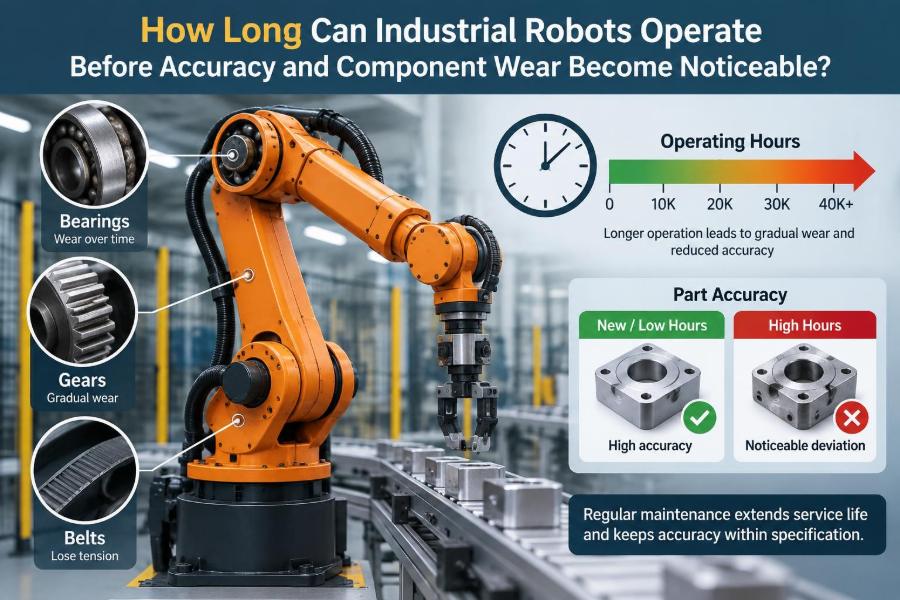
Robots are commonly expected to operate for many years in industrial service, often accumulating tens of thousands of operating hours. But calendar age and powered-on time alone are weak predictors of condition.
A lightly loaded pick-and-place robot moving smoothly in a clean enclosure may remain stable far longer than a similar model making abrupt, high-inertia moves in a foundry. Manufacturer maintenance intervals and the robot’s manual should always take priority over generic rules of thumb.
📈 Noticeable Wear Depends on the Process Tolerance
“Noticeable” is not a property of the robot alone. It is the point at which motion variation becomes large enough to affect the process.
A palletizing operation that places cartons within a broad area may run acceptably despite small mechanical changes. A laser welding, precision dispensing, metrology, or tight-tolerance assembly application may reveal the same change much earlier.
The practical question is: what positional, orientation, and timing error can this process accept? Define that before deciding whether a robot needs intervention.
🦾 The Robot Is a System, Not Just an Arm
When placement drifts, the arm is only one possible source. The complete system includes joints, reducers, bearings, motors, encoders, brakes, cables, controller settings, end-of-arm tooling, fixtures, sensors, and workpiece variation.
A loose gripper jaw, worn locator pin, flexing stand, or shifted camera calibration can mimic robot wear. Effective diagnosis tests the whole process chain rather than replacing expensive robot components based on a visual impression.
⚙️ Gear Reducers Carry Much of the Mechanical Load
Most articulated industrial robots use compact, high-ratio reducers to convert motor speed into controlled joint torque. Common reducer designs are engineered for long life, but their gears, bearings, lubrication, and internal flexing elements experience repeated load cycles.
Wear may first appear as increased backlash: a small difference in joint position when the direction of load reverses. In a multi-axis arm, small amounts of backlash can combine at the tool center point, especially when the arm is extended.
🔩 Bearings Influence Stiffness and Smoothness
Joint bearings support radial, axial, and moment loads. Their condition affects stiffness, friction, vibration, and the robot’s ability to hold orientation under changing tool loads.
Contamination, inadequate lubrication, overloads, and repeated shocks shorten bearing life. Early symptoms can include rough motion, unusual heat, increased vibration, or a position deviation that changes with arm posture rather than remaining constant everywhere.
🛢️ Lubrication Ages Even When Motion Looks Normal
Grease and oil reduce friction, protect contact surfaces, and carry some heat away from loaded components. Over time, lubricant can degrade, separate, become contaminated, or lose its intended properties.
Following prescribed lubricant type, quantity, and interval is not routine paperwork. Using an unsuitable product or overfilling a joint can be as harmful as skipping service, because sealing, churning losses, and heat behavior are part of the design.
🔌 Motors, Encoders, and Cables Also Have Aging Mechanisms
Servo motors rarely “wear” like gears, but heat, contamination, bearing condition, insulation aging, and electrical faults can affect performance. Encoders provide joint position feedback; faults or signal problems can cause alarms, unstable behavior, or lost mastering.
Dress-pack cables deserve attention as well. Repeated bending, twisting, and snagging can damage conductors, shielding, pneumatic lines, and hoses long before the robot’s main structure reaches the end of its useful life.
🌡️ Heat Speeds Up Several Failure Pathways
High ambient temperature, poor cabinet cooling, blocked filters, and continuously demanding motion raise the thermal burden on drives, motors, lubricants, and seals. Temperature also causes temporary dimensional expansion, which can matter in very precise work.
Look for trends rather than one warm day. A joint that becomes hotter than comparable joints during the same proven cycle deserves investigation, particularly if the temperature rise is new.
🏭 Contamination Changes the Maintenance Equation
Dust, abrasive particles, coolant mist, welding fume, humidity, corrosive chemicals, and washdown exposure can attack surfaces and enter places they do not belong. A robot selected for a clean assembly line may need additional protection in a harsh process area.
Protective covers, correct ingress protection, extraction, regular cleaning, and inspection of seals are practical reliability measures. Covers must be installed and maintained correctly; a damaged cover that traps contamination or restricts motion can create a different problem.
📦 Payload Is More Than the Number on the Nameplate
Rated payload is only the starting point. The robot also sees the tool’s center of gravity, inertia, offset from the wrist, cable forces, and the way the payload changes during gripping or dispensing.
A modest tool held far from the flange can create a large wrist moment. Incorrect payload data in the controller can lead to poor motion performance and unnecessary stress because the robot is not calculating dynamics from a realistic model.
🏎️ Fast Direction Changes Are Especially Demanding
Acceleration and deceleration create torque demands that steady-speed motion does not. Short cycles with hard reversals can therefore be tougher on a robot than a slower operation that travels a longer path.
Imagine repeatedly stopping a loaded shopping cart and reversing it. The peak force at each reversal is the issue. Smooth path blending, sensible acceleration limits, and reduced unnecessary oscillation can lower wear without always sacrificing meaningful throughput.
📐 Arm Posture Changes Both Error and Stress
Robot geometry matters. With the arm extended, small joint clearances and structural deflection can produce a larger tool-center-point displacement than they would near the robot base.
Some postures also place more torque on particular joints or approach kinematic singularities, where small joint movements can lead to difficult or rapid orientation changes. A path that is mechanically gentle in simulation may require refinement on the actual installation.
🎯 Distinguish Settling Error From Permanent Drift
A robot that overshoots or vibrates briefly after a fast move may have a dynamic settling issue, not necessarily a permanent position shift. Flexible tooling, loose fixtures, aggressive motion settings, and payload-model errors are common contributors.
Permanent drift is more likely when a repeatable verification path gradually changes across days or weeks. Record measurements under comparable conditions before concluding that mechanical wear is the cause.
🧪 Build a Baseline While the Cell Is Healthy
The best time to measure reference performance is after commissioning, when the process is accepted and stable. Document a small set of representative poses, cycle conditions, tool orientation checks, and quality outputs.
A baseline can include witness marks, gauge readings, vision results, robot controller diagnostics, and joint temperature observations. It gives maintenance teams something far more useful than memory when a future concern appears.
📏 Use the Right Measurement Method
A dial indicator, precision fixture, laser tracker, photogrammetry system, calibrated vision system, or application-specific gauge may be appropriate depending on tolerance and budget. The instrument must be more accurate than the variation being investigated.
For a simple check, move to a fixed pose repeatedly from the same approach direction and then from opposite directions. Differences can help expose backlash or compliance, but this is a screening test, not a substitute for a formal robot performance assessment.
🧷 Check Tool Center Point Calibration First
The tool center point (TCP) is the point on the tool that the controller treats as the working tip. A bumped torch, replaced gripper, bent bracket, or poor TCP calibration creates errors that look exactly like robot positioning trouble.
Recalibrate and verify the TCP whenever tooling changes, then confirm the tool orientation frame where relevant. This is often faster and less invasive than opening a robot joint, and it should be an early diagnostic step.
🗺️ Frames, Fixtures, and Mastering Can Create Global Offsets
User frames and work-object frames describe where the robot believes the fixture is located. If a fixture shifts, a coordinate frame is edited incorrectly, or a vision transform changes, every taught path may be displaced in a consistent way.
Mastering establishes the relationship between encoder counts and physical joint positions. Loss of mastering after a collision, battery-related encoder issue, or service event can create broader positional errors and must be handled using the manufacturer’s approved procedure.
👁️ Process Quality Is Often the Earliest Sensor
Production data can reveal developing problems before a robot fault occurs. Examples include weld seam location trends, increasing touch-up rate, missed insertion force limits, dispensing-bead variation, or a vision system applying progressively larger corrections.
These signals do not prove robot wear. They are evidence to correlate with tool inspection, fixture condition, environmental changes, and robot measurements. Treat quality records as condition-monitoring inputs, not merely output reports.
🚨 Collisions Can Matter More Than Routine Hours
A controlled low-speed contact may cause no lasting damage, but a high-speed collision can load reducers, bearings, wrists, tools, and fixtures beyond normal conditions. The absence of an immediate alarm does not guarantee that nothing moved.
After a significant collision, inspect the tooling and fixture, verify TCP and frames, run a repeatability check, and follow the vendor’s recommended recovery inspection. Do not simply reset the alarm and resume tight-tolerance production.
🧰 Preventive Maintenance Is Scheduled; Predictive Maintenance Is Evidence-Led
Preventive maintenance uses time, cycles, or operating hours to schedule inspections and replacements. It is valuable because it addresses known service needs before a failure interrupts production.
Predictive maintenance uses observed condition: vibration patterns, temperatures, motor current trends, lubricant analysis where applicable, diagnostic codes, or accuracy measurements. It can improve timing decisions, but only if sensors and interpretation are reliable.
| Approach | Best use | Limitation |
|---|---|---|
| Scheduled service | Known lubricant, battery, and inspection intervals | May replace parts before their actual condition demands it |
| Condition monitoring | Detecting unusual trends in critical cells | Requires trustworthy baselines and skilled interpretation |
| Quality-based checks | Linking equipment behavior to the real process | Can be influenced by materials, tooling, and fixtures |
📋 A Practical Inspection Routine
Inspection frequency should reflect the application’s risk and the vendor’s guidance. A critical precision cell may justify frequent quick checks, while a lower-risk handling cell may rely more heavily on scheduled maintenance.
- Listen for new clicking, grinding, or cyclic noises during motion.
- Inspect cables, hoses, covers, fasteners, and tool mounting for damage or looseness.
- Review alarms, motor loads, temperatures, and cycle-time changes for trends.
- Check fixture location and tool condition before attributing defects to the robot.
- Record findings with the same test pose and operating conditions when possible.
🧑🔧 Replacement Decisions Should Be Risk-Based
Component replacement is justified by measured degradation, confirmed fault evidence, manufacturer service requirements, or unacceptable production risk—not by age alone. Replacing a reducer can require specialized procedures, calibration, and verification.
On the other hand, waiting for a severe failure in a bottleneck cell can be costly. Keep critical spares, service contacts, and a recovery plan where downtime consequences warrant them.
🧠 Calibration Can Correct Some Errors, Not Mechanical Looseness
Calibration and compensation can improve absolute positioning when a robot’s geometry and installation are characterized. Vision guidance can also correct for part location variation in many tasks.
Neither approach repairs worn bearings, backlash, a loose tool, or poor stiffness. Software correction may even hide a mechanical trend until it worsens. Use calibration as part of a controlled accuracy strategy, not as a substitute for mechanical health.
🏗️ Cell Design Determines How Gracefully a Robot Ages
Good cell design reduces avoidable loading. This includes selecting adequate reach and payload margin, placing fixtures within favorable working postures, supporting heavy dress packs, avoiding cable snag points, and building a stiff robot base.
It also makes inspection possible. If technicians cannot safely access the wrist, inspect dress packs, or measure a key reference feature, routine maintenance will become slower and less consistent.
⚠️ Common Troubleshooting Mistakes
The most common mistake is reteaching points immediately. Retouching can restore output temporarily while concealing a loose fixture, damaged TCP, degraded reducer, or shifted base.
- Changing several variables at once and losing the evidence trail.
- Testing with a different payload or speed than the production cycle.
- Ignoring approach direction when evaluating backlash.
- Assuming a new robot cannot have calibration, installation, or tool errors.
- Blaming the robot before checking grippers, locators, material variation, and sensors.
📊 A Simple Decision Path When Accuracy Changes
Start by confirming the symptom with an objective check. Determine whether the error is repeatable, whether it changes with direction or posture, and whether it follows the robot, tool, fixture, or part.
- Verify the quality measurement and inspect the workpiece and fixture.
- Check tool mounting, TCP, payload data, and coordinate frames.
- Review recent collisions, maintenance work, program edits, and environment changes.
- Run controlled repeatability and path checks at representative poses.
- Escalate to manufacturer-approved diagnostics if mechanical or mastering issues remain likely.
🧩 Example: A Palletizer and a Welding Cell Age Differently
Consider two hypothetical robots. A palletizer handling consistent cartons may show little production impact from a small positional shift because the pallet pattern has clearance and the gripper self-centers.
A welding robot using a rigid torch near a tight joint may show the same shift as incomplete seam coverage or excessive spatter. The arms might have similar operating hours, but the welding cell detects the problem earlier because its process window is narrower.
🛡️ Safety Must Remain Part of Every Investigation
Accuracy troubleshooting often involves teaching, jogging, measurements, and work inside the safeguarded space. Follow lockout/tagout procedures, site risk assessments, approved reduced-speed modes, and manufacturer instructions.
Never use a person as a physical reference, bypass safeguards for convenience, or treat a robot with suspected brake or control issues as predictable. A positioning problem and a safety problem can coexist.
📚 What Students and New Engineers Should Take Away
Do not frame robot reliability as a countdown clock. Learn to connect mechanics, controls, calibration, process tolerance, and maintenance evidence.
When reviewing a robot application, ask what moves the most, what sees the highest inertia, what contamination is present, where accuracy is measured, and what data would reveal gradual change. Those questions lead to better designs and better fault finding.
✅ The Core Principle: Measure Performance, Then Protect the Mechanism
Industrial robots can deliver dependable motion for long service periods, but wear becomes visible on the timetable set by loading, environment, maintenance quality, and process tolerance. Some changes are temporary control or setup issues; others are genuine mechanical degradation.
The strongest strategy combines correct application design, manufacturer-recommended service, stable baselines, process-quality monitoring, and disciplined diagnosis. That approach avoids both needless component replacement and the costly habit of discovering wear only after quality has failed.
An industrial robot lasts longest when its real operating condition—not a guessed hour limit—guides maintenance and accuracy decisions. 🦾📏⚙️