
A warehouse robot leaves a smooth concrete aisle, crosses a dusty loading bay, and turns toward a pallet. Its wheel encoders report every rotation faithfully. Yet the robot arrives several centimetres away from where its software believes it should be.
The same problem appears outdoors when a delivery rover meets wet paving, when an agricultural vehicle drives through loose soil, or when a small classroom robot spins on a polished floor. The wheels move, but not all of that motion becomes useful travel.
For a person, a slight skid is easy to notice and correct. A mobile robot must infer it from imperfect sensors while continuing to plan, avoid obstacles, and work safely around people.
Wheel slip is therefore more than a traction problem. It is a positioning problem, a control problem, and often a design problem. Understanding how it enters a robot’s estimate is the first step toward making navigation dependable on difficult surfaces.
🧭 What Wheel Slip Actually Means
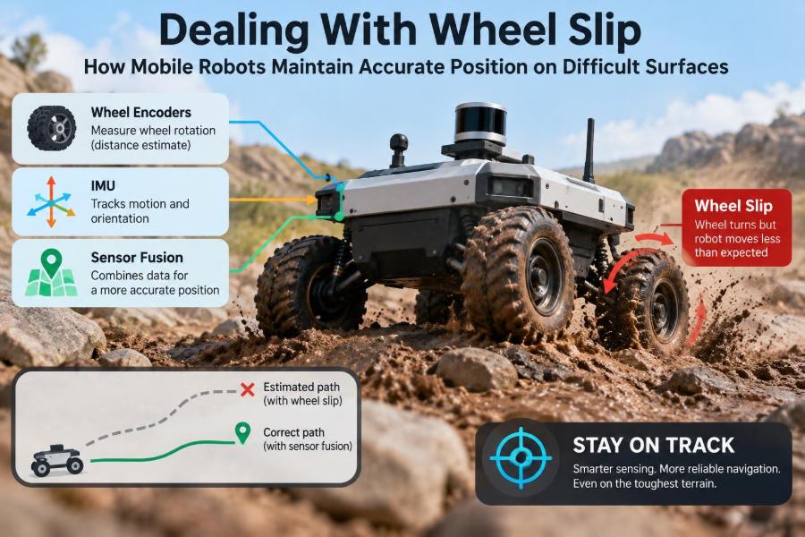
Wheel slip occurs when the motion at the tire or wheel surface does not match the motion between the robot and the ground. An encoder measures wheel rotation, not the distance the robot truly travelled.
During longitudinal slip, a driven wheel spins faster or slower than the ground-contact motion would predict. During lateral slip, the wheel slides sideways, particularly while turning. Both can corrupt position estimates.
📍 Why Position Errors Grow So Quickly
Most wheeled robots estimate short-term motion by integrating encoder readings over time. This process, called odometry, is useful because it is fast, inexpensive, and available even when external signals disappear.
Its weakness is accumulation. If each travelled metre is estimated slightly too long or too short, the error persists in the next estimate. A brief skid can therefore shift the robot’s entire coordinate frame until another measurement corrects it.
⚙️ The Assumption Hidden Inside Odometry
Standard wheel odometry assumes rolling without slip: the contact point between wheel and surface is momentarily stationary relative to the ground. It also assumes an accurate wheel radius, track width, and encoder calibration.
Those assumptions are often reasonable on clean, level floors at moderate speed. They become fragile on slopes, loose material, wet surfaces, uneven terrain, or during aggressive acceleration and braking.
🛞 Longitudinal Slip: Spin and Skid
A robot can lose traction while accelerating when motor torque exceeds what the surface can transmit. The wheels spin, encoders count extra rotation, and odometry falsely reports forward progress.
Braking produces the reverse problem. A wheel may skid while the robot continues moving, so encoders report too little travel. This distinction matters because traction control must manage both driving and stopping.
↔️ Lateral Slip During Turns
Turning introduces side forces. In a differential-drive robot, the two sides are commanded at different speeds; in a car-like robot, steering changes wheel direction. If the surface cannot resist the required sideways force, the robot follows a wider or otherwise different path.
Lateral slip is especially troublesome because a robot may still travel at roughly the expected speed while its heading drifts. A small orientation error changes the direction of every later movement.
🌧️ Surfaces That Change the Rules
Surface condition affects friction, deformation, and contact consistency. Smooth tile can be slippery when wet; carpet can compress; gravel can shift beneath a wheel; mud can pack into tread and change its behavior.
A navigation system should not treat “floor” or “outdoor ground” as a single condition. A route may cross several traction regimes within a few metres, each requiring different confidence in wheel odometry.
📐 Friction Is Not a Fixed Number
Available traction depends on wheel material, tread, normal load, contamination, temperature, texture, and the direction of force. A wheel that grips well while rolling straight may still slide while cornering or crossing a side slope.
Engineers often describe the limit with a friction coefficient, but real contact is variable and difficult to know exactly in operation. Good robot design treats traction as an uncertain quantity, not a constant entered once in a configuration file.
🏋️ Load Transfer Changes Wheel Grip
Acceleration shifts load rearward; braking shifts it forward; a slope shifts it downhill. The wheels carrying less normal force generally have less potential grip.
This can surprise designers of four-wheel robots. A heavy battery, raised payload, or uneven suspension can make one wheel unload first, causing intermittent slip even though the robot appears mechanically stable.
🧱 Terrain Geometry Can Mimic Sensor Failure
Thresholds, cables, potholes, and floor joints can lift or bounce a wheel. An encoder still records rotation, but a partially airborne wheel contributes little or no ground travel.
On rough terrain, suspension motion and chassis pitch also change sensor orientation. What looks like a bad inertial measurement may be a real body movement coupled with unreliable wheel contact.
🔄 Why Differential-Drive Robots Are Vulnerable
Differential-drive platforms are mechanically simple and manoeuvrable, but they turn by creating a speed difference between left and right wheels. Tight turns can demand substantial lateral resistance, particularly on high-grip surfaces or with scrub from additional caster wheels.
A caster that swivels slowly, catches debris, or carries excessive load can add a sideways force that bends the actual path away from the ideal kinematic model.
🚗 Steering Robots Have Different Slip Patterns
Ackermann-steered vehicles, similar in principle to cars, usually avoid intentional wheel scrub in ordinary turns. However, steering angle errors, low-friction ground, and high speed can still create understeer or oversteer-like behavior.
The useful lesson is not that one drive type eliminates slip. It is that each drivetrain needs a motion model and sensor strategy that match its most likely failure modes.
🔍 Recognising Slip Before It Becomes a Big Error
Slip cannot always be measured directly, but it often leaves clues. Encoders may suggest strong acceleration while an inertial measurement unit, or IMU, senses much less body acceleration. A visual tracker may disagree with wheel speed, or motor current may rise while progress falls.
These are residuals: differences between predicted and observed behavior. A residual is not proof of slip by itself, because sensors are noisy and terrain is irregular, but several consistent clues justify reducing trust in odometry.
📊 Use Innovation Checks Rather Than One Threshold
A common mistake is declaring slip whenever wheel speed differs from IMU-derived speed by a single fixed amount. Normal vibration, IMU bias, slope, and encoder quantization can trigger false alarms.
A stronger approach compares the mismatch with expected uncertainty and checks it over a short time window. It can also consider context: high motor command, sudden acceleration, a wet-zone map, or a turning manoeuvre all increase the likelihood that a mismatch is meaningful.
🧠 IMUs Provide Fast Motion Clues
An IMU measures angular rate and linear acceleration. Gyroscopes are particularly valuable for detecting unexpected yaw during a turn, while accelerometers can reveal that encoder-reported acceleration is physically implausible.
IMUs drift when their signals are integrated into velocity or position. They do not replace external localization by themselves, but their high update rate makes them excellent partners for wheel encoders.
👁️ Cameras Can Observe Motion Without Wheel Contact
Visual odometry estimates camera motion from features tracked across images. On a textured, well-lit surface, it can expose wheel slip because it measures apparent scene motion rather than tire rotation.
Its limitations are practical: darkness, glare, motion blur, repetitive patterns, dust on the lens, and moving people can reduce reliability. Cameras should be treated as one source of evidence, not a universal cure.
📡 LiDAR and Range-Based Localization
A laser scanner can align current range measurements with a known map or with recent scans. This scan matching estimates robot motion from walls, shelves, curbs, trees, or other stable geometry.
It works well where distinct stationary structure is available. Long blank corridors, open fields, rain, reflective materials, and frequent layout changes can make the estimate weaker or ambiguous.
🛰️ GNSS Helps Outdoors, With Boundaries
Global navigation satellite system receivers provide an outdoor position reference that does not depend on wheel rotation. They can constrain long-distance drift in fields, campuses, or other open environments.
Accuracy and availability vary with receiver capability, satellite visibility, multipath reflections, correction services, and sky obstruction. Near buildings, under trees, or indoors, GNSS may be intermittent or misleading, so a robot still needs local sensing.
🧩 Sensor Fusion Makes Disagreement Useful
Sensor fusion combines complementary measurements into one estimate. A typical estimator predicts motion using encoders and an IMU, then corrects that prediction with camera, LiDAR, GNSS, landmarks, or other observations.
An extended Kalman filter is a common example, although factor-graph and particle-filter approaches are also used. The essential idea is to represent both an estimate and its uncertainty, then weight measurements by how trustworthy they are under current conditions.
⚖️ Adaptive Confidence Beats Blind Averaging
Fusion fails when it gives a slipping wheel encoder the same confidence it deserves on clean concrete. During suspected slip, the estimator should increase odometry uncertainty or reduce the encoder measurement weight.
This does not mean discarding encoders at the first discrepancy. They remain useful for rapid local motion. The goal is to prevent one compromised source from dominating the robot’s belief.
🗺️ Maps and Landmarks Provide Absolute Corrections
Odometry answers, “How have I moved since the last estimate?” A known map, fiducial marker, docking target, or fixed beacon can answer, “Where am I relative to something stable?”
Periodic absolute corrections stop drift from becoming unbounded. In a warehouse, a robot might relocalize against shelf geometry; in a lab, it might use visual markers sparingly where precision tasks begin.
🧮 Model the Motion You Can Actually Expect
A model that assumes perfect rolling may be too optimistic for a skid-steer rover on dirt. Some applications include estimated slip parameters, terrain-dependent noise, or learned corrections based on command, speed, and sensor history.
More complex models are not automatically better. They require representative validation data and can fail when operating conditions change. A simple model with honest uncertainty often performs more safely than a detailed but overconfident one.
🎛️ Control Strategies That Protect Traction
Localization can correct a position estimate after slip, but control can reduce how often slip occurs. Limit wheel torque or acceleration, ramp speed smoothly, and slow before sharp turns or surface transitions.
Closed-loop wheel-speed control should account for load and motor limits. When independent evidence indicates spin, a traction-control routine can reduce commanded torque until measured body motion again agrees with wheel motion.
🐢 Speed Planning Is a Localization Tool
Reducing speed is not merely a conservative mechanical choice. It gives cameras and LiDAR more time to gather usable measurements, reduces motion blur and vibration, and lowers the forces that demand tire grip.
A practical robot can use different speed limits for known zones: a normal limit on clean aisles, a lower limit near ramps, and a cautious mode on loose or wet ground. The limits should account for stopping distance as well as tracking error.
🛞 Mechanical Choices Matter Upstream
Wheel diameter, compound, tread pattern, tire pressure where applicable, suspension, mass distribution, and ground clearance all affect traction and sensor stability. Software cannot fully compensate for a wheel that is fundamentally unsuitable for the surface.
Wider tires may reduce ground pressure on soft terrain, but they can increase turning resistance. Aggressive tread can improve loose-ground traction while performing poorly or wearing quickly on smooth indoor floors. Design is a trade-off, not a catalogue checklist.
🧹 Maintenance Prevents Quiet Localization Drift
Worn tread, wrapped debris, loose hubs, damaged encoders, uneven tire pressure, and contaminated wheels can introduce errors gradually. These faults are easy to overlook because the robot may still move.
Routine inspection should include checking wheel diameter changes, verifying encoder counts, cleaning contact surfaces, and observing whether the robot tracks straight under repeatable conditions. A calibration performed once at commissioning is not permanent.
🧪 Test on the Surfaces You Will Actually Use
Bench tests on a clean floor establish a baseline, not field readiness. Validation should include representative payloads, slopes, transitions, turning radii, lighting, debris, and expected surface contamination.
Repeatable test paths are useful: command the robot through a route, measure its final pose against a known reference, and compare error patterns across conditions. Record raw sensor data so unexpected behavior can be diagnosed rather than guessed at later.
📈 Measure Uncertainty, Not Just Average Error
An average endpoint error can hide rare but consequential slips. Engineers should examine maximum observed deviations, heading error, relocalization time, and how quickly the estimator recognizes degraded wheel data.
It is also valuable to ask whether the system knows when it is uncertain. A robot that reports low confidence and slows or requests help may be preferable to one that presents a precise-looking but wrong position.
🚧 Safe Behavior When Localization Confidence Falls
When uncertainty exceeds an application-specific limit, the robot needs a defined response. Depending on the environment, that may mean slowing down, stopping, retracing to a landmark, switching routes, or requesting operator assistance.
Safety decisions should be designed around the task and hazards. A robot carrying a light package in an open area can tolerate a different recovery strategy than one operating near people, vehicles, edges, or precision equipment.
❌ Common Mistakes in Slip Handling
- Trusting encoders as ground truth: encoders are precise rotation sensors, not direct distance sensors.
- Using a single sensor as a fallback: every modality has conditions under which it degrades.
- Calibrating only on ideal ground: geometry and traction behavior change with payload and surface.
- Correcting position but ignoring control: frequent slip should trigger gentler motion planning or mechanical review.
- Hiding uncertainty: a navigation stack needs confidence information to make safe decisions.
🔧 A Practical Design Workflow
- Define the surfaces, slopes, payloads, speeds, and allowable position error for the real task.
- Select wheel and drivetrain hardware that can produce reasonable traction in those conditions.
- Calibrate odometry on representative surfaces, then quantify how its error changes elsewhere.
- Add independent sensing such as an IMU and, where appropriate, vision, LiDAR, GNSS, or landmarks.
- Fuse sensors with condition-dependent uncertainty rather than fixed blind trust.
- Test fault responses, including what happens when localization confidence becomes poor.
This workflow connects mechanics, estimation, and safety. Treating them as separate projects usually creates gaps at the exact moments when traction is weakest.
🏁 The Core Principle: Estimate, Verify, Adapt
Accurate mobile robotics on difficult surfaces does not require pretending wheel slip can be eliminated. It requires recognizing that wheel odometry is a valuable prediction source with known failure modes.
Reliable robots estimate movement from wheels, verify it against independent observations, adapt confidence when the evidence disagrees, and adjust their motion before a small skid becomes a navigation failure. Hardware, software, and operating policy must support the same goal.
Wheel slip becomes manageable when a robot treats position as an evidence-based estimate rather than a number its encoders can guarantee. That mindset leads to better sensing, calmer control, and safer recovery when the ground refuses to cooperate. 🦾🧭🌦️