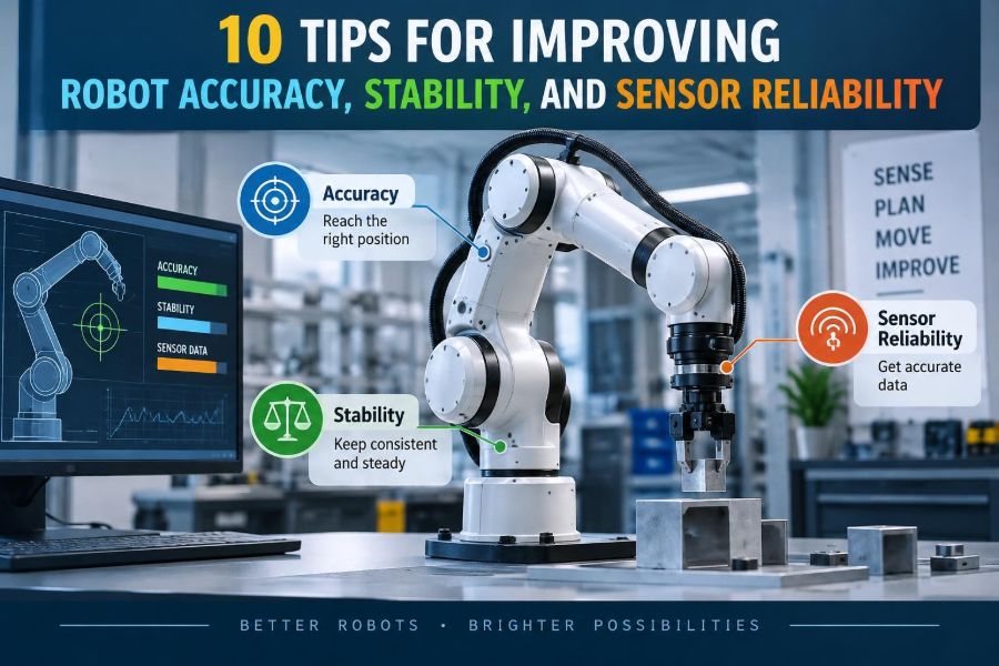

A robot can look flawless during a bench demonstration and still miss a fixture by a few millimetres on the production floor. A mobile robot can navigate a quiet hallway confidently, then begin drifting when sunlight, vibration, wheel slip, and people enter the picture.
Those failures are rarely caused by one dramatic defect. More often, small errors from mechanics, sensors, timing, calibration, software, and the environment combine until the robot’s decisions no longer match reality.
For students, this is the gap between a project that works once and a system that can be measured, debugged, and improved. For working engineers, it is the difference between nominal performance and dependable operation across shifts, sites, and maintenance cycles.
Accuracy, stability, and sensor reliability are connected, but they are not interchangeable. Improving them starts with defining what “good” means, then building a disciplined loop of measurement, diagnosis, correction, and verification.
🎯 1. Define Accuracy Before Trying to Improve It
“Accurate” can mean different things for different robots. A pick-and-place arm may need repeatable tool positioning, while an autonomous vehicle may need reliable lane-relative localization. A camera-guided inspection station may care most about measurement error in an image.
Separate accuracy from repeatability. Accuracy is closeness to the true target; repeatability is the ability to return to the same result. A robot can place a part consistently 2 mm away from its intended location, which is repeatable but inaccurate.
Write a measurable requirement: target, reference frame, error metric, operating conditions, and acceptable limit. This prevents teams from tuning a system toward an unclear goal.
📏 2. Establish a Baseline With Representative Tests
Do not begin by changing gains, filters, or hardware. First measure the current system under conditions that resemble its real job: normal payload, expected speed, typical lighting, floor condition, and cycle duration.
Record more than a single average error. Capture spread, worst observed cases, drift over time, command-to-measurement delay, and the conditions present during each run. A mean value can hide intermittent failures that matter in deployment.
- Repeat the same motion or measurement enough times to reveal variation.
- Test cold startup and warmed-up operation separately.
- Log software version, calibration state, payload, and environmental conditions.
- Keep raw data when possible; summaries cannot answer every later question.
A baseline turns improvement from guesswork into an engineering comparison.
🧭 3. Use Consistent Coordinate Frames
Every robot works through coordinate frames: world, base, joint, tool, camera, map, and part frames. Many apparent “accuracy problems” are actually frame-definition mistakes, such as an incorrect tool-center-point offset or a camera transform applied in the wrong direction.
Document the origin, axis directions, units, and parent-child relationship for each frame. Use one naming convention throughout mechanical drawings, firmware, middleware messages, and test procedures.
When a robot misses by an amount that changes with orientation or workspace location, inspect transformations before assuming the controller is at fault.
🧱 4. Start With Mechanical Rigidity and Backlash
No amount of software filtering can remove physical play from a loose gearbox, flexible mount, worn bearing, or compliant end effector. Backlash is lost motion caused by clearance between mechanical elements; it often appears when an axis reverses direction.
Check fasteners, gear mesh, belt tension, bearing condition, coupling alignment, and fixture stiffness. For an arm, also examine the complete load path from base plate to tool. A rigid arm attached to a flexible bench is still a flexible system.
Mechanical upgrades have trade-offs. Increasing stiffness may add mass, reduce usable speed, or transfer vibration elsewhere. The goal is not maximum stiffness in isolation, but predictable deflection within the task’s tolerance.
⚖️ 5. Match the Payload Model to the Real Tool
Controllers need a reasonable model of payload mass, center of gravity, and inertia to accelerate and decelerate smoothly. An underestimated payload can produce tracking errors, overshoot, or protective stops; an incorrect center of gravity can load joints unevenly.
Include grippers, cables, adapters, vacuum lines, fasteners, and the part being carried. These small additions matter most at the end of a long arm, where leverage amplifies their effect.
Verify performance with the lightest and heaviest expected loads. A tune that works beautifully with an empty gripper may become unstable during the actual production task.
🌊 6. Identify Resonance Instead of Fighting Oscillation Blindly
Resonance occurs when repeated excitation aligns with a structure’s natural tendency to vibrate. It may show up as ringing after a stop, a visible tremor at certain speeds, blurred camera images, or a position error that grows at one particular trajectory frequency.
A simple diagnostic is to run controlled speed or frequency sweeps while observing motor current, accelerometer data, encoder error, or camera motion. Change one variable at a time. If vibration peaks at a repeatable condition, the issue is likely structural or control-related rather than random noise.
Possible remedies include changing trajectory timing, stiffening a mount, relocating mass, adding damping, or using a carefully designed notch filter. A filter can help, but it should not be used to conceal a loose component.
🛞 7. Treat Wheel Slip as a State-Estimation Problem
Wheel encoders estimate distance from rotation, not from actual ground travel. Dust, carpet, ramps, uneven tire wear, acceleration, braking, and a change in payload can all cause slip. A mobile robot that trusts encoder odometry alone will gradually misplace itself.
Fuse encoders with independent observations such as an inertial measurement unit, camera features, lidar scans, magnetic markers, or external references. Sensor fusion estimates the robot state by weighing measurements according to their uncertainty.
Independent does not mean perfect. A lidar can struggle with glass or sparse features, and vision can suffer in poor lighting. The advantage comes from failure modes that are not identical.
🧠 8. Tune Control Loops From the Inside Out
Robotic motion commonly uses nested loops: a fast current or torque loop, then velocity control, then position control. Tuning an outer loop before the inner loops are behaving can create instability and misleading results.
Begin with stable low-level actuator behavior, then tune velocity response, then position tracking. Increase performance gradually while observing overshoot, settling time, steady-state error, and oscillation. Keep a record of each parameter change and its effect.
High gain is not automatically better. Excessive proportional gain can cause ringing, while too much integral action can accumulate error and overshoot after a disturbance. A controller must be responsive without demanding motion the mechanics cannot deliver.
⏱️ 9. Control Latency, Jitter, and Clock Alignment
Latency is delay; jitter is variation in delay. Both matter when a robot uses a sensor reading to make a fast decision. A vision measurement that arrives late may describe where an object was, not where it is now.
Timestamp data close to its source, synchronize clocks where the architecture permits, and measure end-to-end delay from physical event to actuator command. Avoid assuming a nominal camera frame rate or network interval represents actual timing.
For moving targets, compensate using a motion model only when the model is justified and its uncertainty is understood. Prediction can reduce apparent lag, but poor prediction can create a new source of error.
📸 10. Choose Sensors for the Failure Modes, Not the Datasheet Peak
A sensor’s headline resolution or range is only one part of suitability. Consider surface material, viewing angle, reflectivity, ambient light, temperature, vibration, update rate, mounting constraints, and cleaning requirements.
For example, an optical distance sensor may perform well on a matte target yet behave differently on shiny metal or dark fabric. A depth camera may provide rich information indoors but need careful testing in intense sunlight.
| Sensor type | Useful strength | Common limitation to test |
|---|---|---|
| Encoder | Precise relative motion | Slip, missed counts, reference loss |
| IMU | Fast rotational and acceleration data | Bias drift and vibration sensitivity |
| Camera | Rich scene information | Lighting, motion blur, occlusion |
| Lidar | Geometric ranging | Reflective, transparent, or sparse surfaces |
Selecting by operating conditions is usually more valuable than selecting by one maximum specification.
🔧 11. Mount Sensors Like Measurement Instruments
A carefully calibrated sensor mounted on a vibrating bracket is not a reliable measurement system. Mounting affects alignment, thermal movement, vibration transmission, cable strain, and serviceability.
Use rigid, repeatable mounts and protect sensor fields of view from moving cables or tool components. If a camera is used for calibration, its mount must remain unchanged after calibration; a small bump can invalidate a precise transform.
Consider maintenance as part of the design. A sensor that cannot be cleaned, inspected, or re-seated consistently will become less trustworthy over time.
🧪 12. Calibrate What Actually Changes the Result
Calibration estimates parameters that connect a measurement or command to physical reality. Common examples include camera intrinsics, camera-to-robot pose, encoder scale, IMU bias, tool center point, and joint zero offsets.
Calibrate at the precision level the task needs. An elaborate procedure is not useful if technicians cannot repeat it, while a simplistic procedure may be inadequate for tight-tolerance assembly.
Useful calibration checks
- Validate with targets or poses not used during calibration.
- Check residual errors across the full working area, not only near the center.
- Save calibration version, date, method, and fixture identity.
- Recalibrate after a collision, sensor replacement, structural adjustment, or meaningful temperature change.
Calibration is a measurement process, not a one-time button press.
🌡️ 13. Account for Thermal Drift
Motors warm up, electronics heat, metal structures expand, and sensors can shift bias as temperature changes. The effect may be modest, but small changes matter in precision tasks and long production cycles.
Measure cold and warm behavior separately. If the difference is meaningful, allow a controlled warm-up, model temperature-dependent corrections, improve cooling, or schedule calibration after the system reaches normal operating conditions.
Do not apply a correction derived from one environment without validating it elsewhere. Thermal behavior depends on airflow, duty cycle, payload, enclosure design, and ambient conditions.
🧹 14. Protect the Measurement Path From Contamination
Dust on a camera lens, grease on a fiducial marker, condensation on a lidar window, and debris under a wheel can each look like a software bug. The sensor may be functioning exactly as built while receiving degraded physical input.
Design protective covers, air flow, wipers, cleaning access, and inspection intervals according to the environment. A cover must not introduce reflections, distortion, or obstruction that harms the sensor more than the contamination would.
Track sensor health indicators where available, such as image brightness, returned-range quality, or invalid measurement rate. These trends can signal gradual degradation before a task fails.
💡 15. Control Lighting for Vision-Guided Robots
Vision systems measure reflected light, so lighting is part of the sensor system. Changing daylight, flickering fixtures, shadows from operators, glossy parts, and automatic camera exposure can all shift image appearance.
Use controlled illumination when the task permits it. Diffuse light can reduce harsh reflections; backlighting can make a part outline easy to detect; polarized arrangements can sometimes reduce glare from shiny surfaces.
Locking exposure and gain may improve repeatability in a stable cell, but it can reduce adaptability when lighting truly changes. Test the chosen strategy with realistic part finishes and background conditions.
📡 16. Build Redundancy Around Credible Failure Modes
Redundancy is not simply adding more sensors. It is arranging independent evidence so that the system can detect, tolerate, or safely respond to a plausible failure.
A mobile robot might compare encoder-based motion against IMU behavior and map-based localization. A gripper might combine commanded motor current with a force or position check to distinguish a secure grasp from an obstruction.
Redundant sensors can agree for the wrong reason if they share the same mount, power supply, environmental exposure, or software assumption. Examine common-cause failures before calling an architecture fault tolerant.
✅ 17. Add Plausibility Checks and Confidence Gates
Every measurement should be treated as a claim, not an unquestionable fact. Plausibility checks reject values that are physically impossible, stale, out of range, inconsistent with nearby measurements, or inconsistent with the robot’s current state.
For example, if a robot’s localization suddenly jumps several metres while wheel speed is near zero, the software can flag the estimate rather than immediately steering toward the new position.
Use confidence thresholds carefully. A threshold that is too strict can reject usable data; one that is too loose lets unreliable data drive decisions. Log rejected samples so the team can learn whether the gate is correctly set.
🗂️ 18. Log the Signals Needed to Reproduce a Failure
When an intermittent error occurs, a final alarm code is rarely enough. Log commands, measured states, relevant sensor values, timestamps, controller modes, fault flags, and environmental context where practical.
Use synchronized logs and preserve the sequence around an event. The key question is often not “what value was wrong?” but “what changed first?” A voltage dip, late packet, mode switch, or rising vibration may precede the obvious error.
Logging has costs in bandwidth, storage, and privacy. Decide in advance what full-rate data is needed continuously, what can be triggered on anomalies, and how long records should be retained.
🧩 19. Isolate Variables During Troubleshooting
Changing hardware, firmware, calibration, and controller gains in one session may appear productive, but it destroys causal evidence. If performance improves or worsens, nobody knows why.
Use controlled comparisons: hold the route constant while changing lighting, hold payload constant while changing speed, or replay recorded sensor data through a revised algorithm. A structured test matrix makes interactions visible without requiring every possible combination.
When the robot is unsafe to test at full speed, use simulation, reduced speed, or a constrained fixture first. These are useful screening tools, but final verification still needs representative physical conditions.
🧯 20. Design Safe Degraded Modes
Sensor reliability does not mean every reading will always be available. A robust robot defines what it does when confidence drops: slow down, stop, request assistance, switch to another localization method, or complete only a safe subset of the task.
The correct response depends on hazard and context. An inspection system may flag a part for manual review, while a robot near people may need a conservative stop. Safety functions should be designed and validated under the applicable requirements for the specific machine and workplace.
Do not let a fallback mode silently become the normal mode. Surface it in diagnostics and maintenance reports.
🧭 21. Test the Edges of the Operating Envelope
Robots are often validated under ideal conditions, then deployed at the boundaries: maximum payload, minimum battery state, longest cable routing, cold mornings, reflective parts, steep ramps, or crowded routes.
Create tests around known sensitivities and credible misuse. Include recovery after a restart, temporary sensor obstruction, a changed fixture, and normal wear. The aim is not to prove that every extreme is harmless, but to understand the boundary where performance becomes unacceptable.
State those limits clearly in operating procedures. Hidden limits are eventually discovered by operators at the worst possible moment.
🔁 22. Verify Changes With Regression Tests
A new filter may reduce noise but add delay. A stronger bracket may improve camera stability but obstruct a field of view. An updated localization algorithm may improve one building layout and weaken performance in another.
Regression testing repeats a defined set of earlier checks after a change. Keep a practical suite that includes accuracy, settling, sensor dropout handling, timing, safety-related behavior, and representative task completion.
Compare against the baseline rather than relying on subjective impressions. “It seems smoother” is useful feedback; it is not sufficient evidence for a production decision.
🛠️ 23. Create Maintenance Triggers, Not Just Calendar Tasks
Calendar-based maintenance is useful, but condition-based triggers can catch problems that develop faster or slower than expected. Rising motor current, increased position residual, worsening image contrast, repeated localization corrections, or growing vibration can indicate a need for inspection.
Choose indicators tied to known failure mechanisms. A metric is valuable only if a technician can interpret it and take a sensible action.
After maintenance, confirm that the fix worked with a short acceptance test. Tightening a mount or replacing a sensor can change alignment and require recalibration.
👥 24. Include Operators and Technicians in the Feedback Loop
People who load parts, clean sensors, change tools, and recover faults often see the earliest signs of degraded performance. Their observations can reveal conditions that engineering tests did not reproduce.
Give them clear guidance: what normal behavior looks like, what symptoms to report, which surfaces may be cleaned, and which adjustments require trained service personnel. Avoid procedures that depend on hidden judgment or undocumented “feel.”
A useful fault report includes the task being performed, visible conditions, recent changes, and whether the issue repeats. This makes field feedback actionable rather than anecdotal.
📉 25. Avoid Common Accuracy “Fixes” That Create New Problems
Several tempting fixes provide short-term relief while making the system harder to trust. Repeatedly adding offsets can mask a frame or mechanical issue. Heavy filtering can make noisy data look clean while delaying it beyond usefulness. Raising control gains can improve one step response while introducing vibration elsewhere.
- Do not calibrate around a loose or shifting mount.
- Do not average away an intermittent failure without investigating its cause.
- Do not validate only the nominal path, payload, or lighting condition.
- Do not assume a sensor fault when timestamps, transforms, or units have not been checked.
The best correction addresses the dominant cause and leaves a clear explanation for the next engineer.
📈 26. Use an Improvement Loop Instead of One-Time Tuning
Reliable performance comes from a loop: define the task metric, measure the baseline, identify likely contributors, change one justified variable, verify across conditions, and preserve the evidence. Repeat as the robot, process, and environment evolve.
This approach also helps prioritize. Fixing a major source of mechanical motion or timing error generally delivers more value than chasing tiny sensor noise that the task can already tolerate.
Good engineering judgment means knowing when a system is accurate enough for its intended work, when it needs a redesign, and when uncertainty should trigger a safer operating mode.
🦾 The Core Principle: Make the Robot Earn Your Trust
Robot accuracy is not a property delivered by one premium component or one clever algorithm. It emerges from aligned mechanics, well-defined frames, stable control, appropriate sensing, disciplined timing, and validation under real conditions.
Sensor reliability follows the same principle. Protect the measurement path, understand where each sensor is weak, compare independent evidence, and make uncertainty visible to the control system and to the people maintaining it.
The strongest systems are not those that never encounter imperfect data or changing conditions. They are the systems that detect those conditions, respond predictably, and provide enough evidence for engineers to improve the next cycle.
Build robots around measured reality rather than ideal assumptions, and accuracy, stability, and reliability become manageable engineering outcomes. 🦾📏🔍