
A small mobile robot seems simple at first: attach two motors, add wheels, connect a sensor, and let it drive. Yet many first builds do something less graceful. They spin in place, reset when the motors start, report impossible sensor values, or move backward when the program says forward.
Those failures are useful clues. A mobile robot is a compact system where mechanics, electronics, power, and software all meet. A problem in one part can look like a fault somewhere else.
Learning to set up sensors and motors properly turns a pile of parts into a machine that can perceive its surroundings and respond predictably. The same habits also transfer to larger robots, automation projects, and embedded systems.
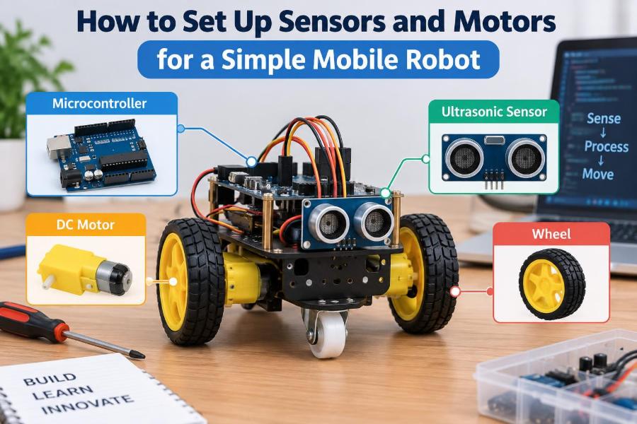
This guide uses a typical two-wheel differential-drive robot as the example: two driven wheels, a free caster or skid, a microcontroller, a motor driver, a battery, and one or more sensors. The details vary by hardware, but the reasoning remains the same.
🤖 Start with the Robot’s Job
Choose the behavior before selecting components. A line-following robot needs downward-facing reflectance sensors; an obstacle-avoiding robot needs a way to estimate nearby distance; a remote-controlled rover may need only motors and a receiver.
Write one short requirement such as: “Drive forward on a clear floor and stop when an object is close.” That sentence identifies the essential inputs, outputs, and decisions without making the first version too ambitious.
🗺️ Understand the Basic Signal Path
A mobile robot works as a loop: sensors measure the environment, the controller interprets those signals, and the motor driver supplies power to make the motors move. Movement changes what the sensors observe, so the loop repeats many times each second.
The microcontroller should not power motors directly. Its pins are designed for low-current logic signals, while motors can draw substantially more current, especially when starting or stalled.
🧰 Choose a Practical Minimum Parts Set
A first robot is easiest to debug when every part has a clear purpose. A sensible minimum setup includes:
- a microcontroller board with enough input/output pins,
- two geared DC motors and wheels,
- a dual-channel motor driver matched to the motors,
- a battery or battery pack appropriate for the driver and motors,
- a stable frame, caster, or low-friction skid,
- one sensor module and connecting wires,
- a power switch and, ideally, a fuse or protected battery pack.
Do not assume a motor driver module is automatically compatible. Check its allowed motor voltage, continuous current capability, logic voltage requirements, and heat dissipation needs.
⚙️ Pick Motors for Torque, Not Just Speed
Small geared DC motors are common because their gearbox trades high motor speed for useful wheel torque. Torque is the twisting force that lets a wheel start moving the robot, climb a small transition, or push through carpet resistance.
A motor that looks fast while held in the air may be disappointing on the floor. Wheel diameter matters too: larger wheels travel farther per revolution but require more torque at the axle for the same pushing force.
For a first build, prioritize slow, controllable motion over maximum speed. A robot that moves steadily at modest speed gives sensors and software time to react.
📏 Estimate the Mechanical Load
Before wiring, place the chassis on its wheels and check that it rolls freely. Misaligned motor brackets, a caster that binds, or a battery mounted too far to one side can make straight driving difficult even with perfect code.
Keep heavy items low and near the center. A high battery pack shifts the center of mass upward, making the robot more likely to rock or lose traction during turns.
🔄 Learn Differential Drive
With two independently driven side wheels, direction comes from the relationship between left and right wheel speeds. This arrangement is called differential drive.
| Left wheel | Right wheel | Expected motion |
|---|---|---|
| Forward | Forward | Drive forward |
| Reverse | Reverse | Drive backward |
| Forward | Reverse | Turn in place |
| Faster forward | Slower forward | Curve toward the slower side |
The words “left” and “right” should always mean the robot’s left and right as viewed from behind it. Establish this convention early; it prevents confusing reversals in wiring and code.
🔌 Use a Motor Driver as the Power Interface
A DC motor driver is an electronic bridge between the controller and motors. Most dual drivers use an H-bridge, a circuit that can reverse the polarity across a motor and therefore reverse its rotation.
Typical driver connections include motor power, ground, two outputs per motor, logic inputs for direction, and often enable or PWM inputs for speed. Read the module’s pin labels rather than relying on a generic wiring diagram; boards with similar appearances can differ.
🔋 Design Power Before Connecting Wires
Motors create current surges when they start, reverse, or stall. If the battery or wiring cannot provide that current, the controller voltage may dip and cause random resets, sensor glitches, or corrupted serial output.
Use a supply arrangement that meets the motor driver’s requirements and provides regulated power to the microcontroller when needed. Some boards include a regulator, but its safe input range and current capacity must be checked rather than assumed.
Never power motors from a microcontroller’s logic output pin. It can damage the board or create unstable behavior.
🌍 Make Every Circuit Share Ground
The controller’s logic signals need a common voltage reference with the motor driver. Connect the controller ground and driver logic ground together, even if the motors use a separate battery source.
Without a shared ground, a “high” or “low” signal may have no meaningful reference at the driver. This omission is a frequent reason a correctly written program appears to do nothing.
🛡️ Add Basic Power Protection
Fit a reachable power switch so the robot can be stopped immediately during testing. Avoid loose bare conductors, especially around battery terminals, because a short circuit can heat wires and damage cells quickly.
Reverse-polarity protection, a fuse, or a protected battery pack can reduce the consequences of wiring errors. These measures do not replace careful work, but they make experimentation more forgiving.
🧱 Mount Motors Rigidly
Secure each motor so its shaft and wheel stay aligned with the chassis. A motor that flexes in its bracket converts energy into vibration, can loosen wiring, and changes the wheel contact pattern while driving.
Make sure wheels do not rub against the frame or motor leads. Route wires with enough slack for removal but not so much that they can enter a wheel.
🧭 Verify Motor Direction One Side at a Time
Run one motor at low power before attempting full vehicle motion. Decide what electrical direction means “forward” for that wheel, label it, and repeat for the other side.
Because mirrored motors are mounted opposite each other, identical polarity often makes the wheels rotate in opposite vehicle directions. Fix this either by swapping a motor’s two output wires or by reversing that channel in software. Choose one method and document it.
🎚️ Control Speed with PWM
Pulse-width modulation, usually shortened to PWM, controls average motor power by switching it on and off rapidly. A higher duty cycle leaves power on for more of each cycle and generally produces more speed and torque.
PWM is not a direct speed measurement. A motor’s actual speed still changes with battery voltage, floor friction, payload, and slope. It is a useful open-loop command, not a promise that both wheels are moving equally fast.
🧪 Begin with a Motor Test Program
Write a minimal test routine before combining motors with sensor logic. It should command left forward, left reverse, right forward, right reverse, both forward, both reverse, and stop.
Keep the robot lifted so wheels can spin freely for the first check. Then test on the floor at low duty cycle, where unexpected motion is easier to control.
setLeftMotor(forward, 90)
setRightMotor(forward, 90)
wait(500)
stopMotors()
The exact syntax depends on the platform. The useful pattern is explicit: set direction, set a modest command, wait briefly, then stop.
📐 Correct for Unequal Wheel Behavior
Two nominally identical motors rarely behave identically. Gear friction, wheel diameter, and loading differences can cause a robot to drift even when both PWM values match.
Start by checking mechanical causes: loose wheels, unequal tire contact, chassis twist, and a dragging caster. If the mechanics are sound, apply a small software trim, such as slightly reducing power to the faster side.
Trim works acceptably on a consistent surface. For repeatable travel over changing conditions, use wheel encoders and feedback control.
👁️ Match the Sensor to the Question
Sensors do not simply “see”; each one answers a limited physical question. An ultrasonic range sensor estimates distance using sound reflections. An infrared proximity sensor responds to reflected infrared light. A bumper switch reports contact. Encoders report wheel rotation.
Select a sensor based on the decision the robot must make, the environment, and likely failure modes. An obstacle sensor that works against a pale wall may behave differently with a soft fabric surface, glass, angled objects, or bright sunlight.
📡 Understand Distance-Sensing Limits
Ultrasonic sensors can be useful for detecting reasonably solid objects in front of a robot, but their readings depend on echo quality and target angle. Soft materials may absorb sound, while angled flat surfaces may reflect sound away from the receiver.
Infrared distance or proximity sensors are compact and fast, but surface color and ambient light can influence them. Treat any single range reading as an estimate, not a perfect map of the world.
📍 Position Sensors for the Behavior You Want
Place a forward obstacle sensor high enough that its view is not blocked by the chassis, but low enough to detect the hazards that matter. A sensor mounted too high can miss a short box; one mounted too low may mostly observe the floor.
For line following, mount reflectance sensors near the ground and ahead of the drive axle. This gives the controller time to steer before the wheels pass over a line edge.
Keep sensing areas clear of cables, shiny brackets, and moving wheel parts. The physical field of view matters as much as the wiring diagram.
🔧 Wire Digital and Analog Signals Carefully
A digital sensor generally reports a state such as high/low, detected/not detected, or a timed pulse. An analog sensor produces a varying voltage that the controller converts into a number using an analog-to-digital converter.
Check the signal voltage before connecting it to a microcontroller input. A sensor output that exceeds the input’s safe voltage can damage the controller. Some modules need level shifting or a voltage divider when paired with lower-voltage logic.
🧹 Keep Sensor Wiring Away from Motor Noise
Brushed DC motors generate electrical noise as their internal contacts switch. Long sensor leads routed alongside motor power wires can pick up interference, producing erratic values.
Use short, secure signal leads where possible. Route motor power and sensitive sensor wiring separately, and ensure motor-driver connections are tight. Decoupling capacitors are often used near electronics to absorb short voltage disturbances; follow the recommendations for your specific boards.
📊 Read Raw Values Before Choosing Thresholds
Do not guess the number that means “obstacle close” or “line detected.” First print or display raw sensor readings while moving known objects or surfaces through the sensor’s operating range.
For example, a line sensor should be observed over both the intended line and the surrounding floor under the lighting where it will run. Then choose a threshold between the observed ranges, leaving margin for ordinary variation.
⏱️ Filter Noise Without Making the Robot Blind
Single readings can jump because of reflections, vibration, electrical noise, or sensor limitations. A simple filter can make decisions more stable: take several readings and use a median or average, or require a condition to persist briefly before acting.
Filtering adds delay. If a fast robot waits too long to believe its sensor, it may travel farther than intended before braking. Tune filtering and speed together rather than treating them as separate settings.
🚦 Build Simple, Explicit Robot States
Instead of a long chain of overlapping conditions, organize behavior into states such as drive, stop, reverse, and turn. A state describes what the robot is doing now and the rule that causes it to change.
For a basic obstacle-avoidance example, the robot can drive while distance is clear, stop when an object is detected, reverse briefly, turn, and then return to drive. This is easier to test than trying to improvise every motor action inside one sensor-reading statement.
🛑 Define a Safe Default State
When the controller starts, resets, loses a sensor reading, or encounters an unexpected condition, the safest default is usually motors off. Make that behavior deliberate in both hardware and software.
Do not assume the driver inputs will always settle into a harmless state during startup. Pull-down or pull-up arrangements, enable pins, and software initialization depend on the hardware design. Test power-up behavior with wheels raised.
🧠 Add Encoders When Accuracy Matters
Wheel encoders produce pulses as a wheel or motor shaft turns. By counting pulses, the controller can estimate wheel rotation and compare left and right travel.
Encoders make closed-loop speed control and distance estimates possible, but they do not remove all error. Wheels can slip, tire compression changes effective diameter, and the robot may rotate slightly while one wheel loses traction.
For classroom navigation on a smooth floor, encoder feedback is a major improvement. For a first reactive robot, it is reasonable to begin without it and add it after the basic system works.
📉 Respect Battery Voltage Changes
A battery’s voltage and ability to deliver current change as it discharges. A PWM value that gives a useful crawl at the start of a session may produce weaker movement later.
Monitor battery condition where practical, and stop testing before cells are over-discharged according to their chemistry and manufacturer guidance. Rechargeable battery types have different handling requirements; use an appropriate charger and never mix cells carelessly.
🔥 Plan for Heat and Stalls
A stalled motor is one that receives power but cannot rotate, such as when a wheel is wedged against an obstacle. It can draw much more current than during ordinary motion, heating the motor, driver, battery, and wires.
Design so the robot can stop rather than push indefinitely. If a driver becomes unusually hot, disconnect power and investigate motor load, wiring, supply voltage, and the driver’s current rating before continuing.
🧰 Debug in a Controlled Order
When the robot misbehaves, changing wiring, code, and mechanics all at once hides the cause. Test from the simplest layer upward:
- Confirm battery polarity and supply voltages with a meter if available.
- Confirm common ground and driver enable conditions.
- Test each motor channel without sensor decisions.
- Read each sensor independently and inspect raw values.
- Combine one sensor condition with one safe motor action.
- Add states, filtering, and speed tuning only after basic behavior works.
This order turns “the robot does not work” into smaller questions with observable answers.
⚠️ Avoid Common First-Build Mistakes
Several mistakes recur because they are not obvious from the finished robot:
- using a weak supply that works with unloaded wheels but resets under floor load,
- forgetting common ground between controller and motor driver,
- testing at full speed before confirming wheel direction,
- mounting sensors where wheels, cables, or the chassis block them,
- choosing thresholds without observing real sensor readings,
- assuming equal PWM commands create equal wheel speed,
- leaving no quick way to cut motor power.
None of these are signs of poor ability. They are normal integration issues, and systematic testing is the solution.
📝 Keep a Wiring Map and Test Notes
Record which controller pin connects to each driver input, which motor is left or right, sensor supply voltage, and the forward direction for each channel. A labeled sketch is often more valuable than memory after the robot has been disassembled.
Also record working PWM values, sensor ranges, and changes made during testing. This makes improvements reproducible and helps distinguish a new fault from an old limitation.
🚀 Grow the Robot in Small Steps
Once the robot drives safely and senses reliably, extend one capability at a time. Add a second distance sensor for side awareness, an encoder for straighter travel, or a line sensor array for tracking a path.
Each addition changes power use, wiring complexity, and software timing. Retest the existing behavior after every modification rather than assuming a new feature is isolated.
✅ The Core Principle: Integrate, Measure, Then Refine
A dependable mobile robot does not come from connecting the most parts. It comes from matching motors to load, isolating motor power from sensitive logic, mounting sensors for a real field of view, and observing actual signals before writing complex behavior.
Build the robot as a sequence of verified layers: stable chassis, safe power, individual motor control, trustworthy sensor data, then decision logic. That sequence makes faults visible and gives every later improvement a sound foundation.
The best first mobile robot is not the fastest or most elaborate one; it is the one whose sensors, motors, power system, and code behave predictably together. With that foundation, more capable autonomous behavior becomes an engineering problem you can solve step by step. 🦾🔧🤖