
A robot can execute the same program thousands of times and still miss its target. A gripper that should enter a machine fixture may arrive a few millimeters to the side. A mobile robot may report that it is at a shelf while its wheels are actually slightly short of it.
These errors rarely come from one dramatic failure. More often, small inaccuracies accumulate: a camera is mounted a little differently than expected, an encoder slips by a fraction, a floor is uneven, or a coordinate frame was measured incorrectly.
For a student, positioning error can turn a promising prototype into an unreliable demonstration. For a working engineer, it can create quality defects, longer cycle times, safety concerns, and difficult commissioning work.
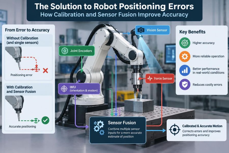
The practical answer is not simply buying a more expensive sensor. Reliable positioning comes from understanding where error enters the system, calibrating the relationships between components, and combining sensor measurements intelligently.
🎯 What Robot Positioning Error Actually Means
Positioning error is the difference between where a robot believes it is and where it physically is, or between the commanded target and the achieved pose. A pose includes both position and orientation: not only where the tool is, but also how it is rotated.
A robot can be accurate in one sense and inaccurate in another. It might repeat the same slightly wrong motion extremely well, or it might reach the correct location on average while varying from cycle to cycle.
📏 Accuracy, Repeatability, and Resolution Are Different
Accuracy describes closeness to the intended physical target. Repeatability describes how consistently the robot returns to the same pose. Resolution is the smallest change a system can represent or command.
Consider a pick-and-place arm that consistently stops 2 mm left of a fixture. Its repeatability may be excellent even though its absolute accuracy is poor. Calibration can often correct this systematic offset; random variation is harder to remove.
🧭 Why Coordinate Frames Control Everything
Robots operate through coordinate frames: mathematical reference systems attached to the robot base, joints, tool, camera, workpiece, and sometimes the world. A measurement only has meaning when its frame is known.
If a vision system identifies an object in camera coordinates, the controller must transform that result into the robot base frame. A small error in this transformation can become a visible error at the gripper.
🔗 The Transform Chain Behind a Motion
A typical manipulation task relies on a chain of transformations: base to robot flange, flange to tool center point, camera to base or flange, and object to camera. Each link contributes uncertainty.
This is why a robot may move correctly in simulation yet miss a real object. Simulation often assumes perfect geometry, rigid mounts, and exact coordinate-frame alignment. Physical systems must estimate those relationships.
🧱 Mechanical Sources of Positioning Drift
Mechanical error is not always a software problem. Gear backlash, bearing wear, joint compliance, loose fasteners, cable forces, and thermal expansion can alter the relation between commanded and actual pose.
A long arm carrying a heavy tool may sag differently at different reaches. Calibrating one pose cannot fully compensate for a load-dependent deflection across the entire workspace.
🌡️ Temperature Changes Geometry
Motors, gearboxes, structures, and sensors warm during operation. As materials expand and components settle, measurements and kinematic behavior can shift. The effect may be small, but precision tasks can expose it.
For demanding applications, calibration and validation should occur under representative operating conditions. A cold-start calibration may not describe a system after hours of production.
🛞 Wheel Odometry and the Problem of Slip
Mobile robots commonly estimate motion from wheel encoders, a process called odometry. If wheel radius, axle spacing, or encoder scale is wrong, the estimated path drifts even on a clean floor.
Slip makes the problem worse. A wheel can rotate without producing the expected travel, especially during rapid turns, threshold crossings, braking, or motion on dust and uneven surfaces. Encoders still report rotation, but they cannot directly tell that traction was lost.
📷 Vision Measurements Have Their Own Errors
Cameras add valuable scene information, but a pixel measurement is not automatically a precise spatial measurement. Lens distortion, poor focus, motion blur, lighting changes, reflective surfaces, and imperfect object detection all affect results.
Depth cameras and stereo systems also have range-dependent behavior and difficulty with certain materials. A sensor should be characterized in the environment where it will work, not judged only by a specification sheet.
📡 IMUs Sense Motion, but They Drift
An inertial measurement unit, or IMU, contains accelerometers and gyroscopes. It measures acceleration and angular rate at high speed, making it useful when vision is blurred or temporarily blocked.
However, integrating noisy acceleration into velocity and then position causes drift. Gyroscope bias can also cause an orientation estimate to slowly rotate away from reality. An IMU is powerful, but it needs correction from other information.
📐 Calibration Is Measuring the System You Actually Built
Calibration estimates parameters that connect measurements to physical reality. Rather than assuming a camera has an ideal lens or a tool is mounted exactly as designed, calibration measures the deviations that matter.
It is best viewed as a model-fitting process. The system collects observations of known targets or motions, then finds parameter values that make predicted measurements agree as closely as practical with observations.
🦾 Robot Kinematic Calibration
Robot kinematics convert joint positions into an estimated tool pose. The model depends on quantities such as link lengths, joint offsets, and joint-axis alignment. Manufacturing tolerances and assembly variation mean nominal values are rarely perfect.
Kinematic calibration identifies corrections to these parameters using external measurements or carefully designed contact procedures. It can improve absolute positioning, particularly over larger workspaces, but it cannot eliminate flexible deformation or changing loads.
🔧 Tool Center Point Calibration
The tool center point, often called the TCP, is the point on the end effector used for robot programming. For a gripper, it might be between the fingers; for a welding torch, it may be near the wire tip.
If the TCP is wrong, every path is wrong relative to the tool. A common procedure rotates the tool around a fixed physical point and solves for the offset between the robot flange and that point.
👁️ Camera Intrinsic Calibration
Intrinsic calibration estimates the camera’s internal imaging behavior: focal length, principal point, and lens distortion parameters. These values allow software to map image points more realistically to viewing rays.
Calibration boards with known patterns are often used because their geometry is defined. Good data includes the target at multiple distances, positions, and orientations rather than clustered in the center of the image.
🤝 Hand-Eye Calibration Connects Vision to Motion
Hand-eye calibration finds the fixed transformation between a camera and a robot. In an eye-in-hand arrangement, the camera moves with the wrist. In an eye-to-hand arrangement, the camera is mounted in the workcell and observes the robot.
The name reflects the core question: how is the robot “hand” positioned relative to its “eye”? Without this relationship, object detections cannot be converted reliably into reachable robot poses.
🗺️ Map Alignment for Mobile Robots
A mobile robot also needs a relationship between its local sensors and its map. If a map was created in one coordinate system and the robot localizes in another, the systems must be aligned consistently.
Map errors, moved furniture, changing racks, and look-alike corridors can all complicate localization. Calibration alone does not solve an outdated or ambiguous map; the environment model must be managed too.
✅ Designing a Useful Calibration Procedure
A calibration routine should be repeatable, observable, and tied to the task. “Observable” means the collected data must contain enough variation to reveal the parameters being estimated.
- Secure mounts and inspect mechanical play before collecting data.
- Use a target or reference whose geometry is known well enough for the required tolerance.
- Sample across the intended workspace, not only one convenient pose.
- Keep records of sensor settings, tool configuration, and environmental conditions.
- Validate with data that was not used to fit the calibration.
A low residual during calibration is encouraging, but it does not by itself prove performance on a new task.
🧪 Validation Must Use Real Task Conditions
Validation asks a different question from calibration: does the corrected system perform adequately where it will be used? A camera-to-robot transform can fit a calibration board well while still producing poor picks near the edge of the workspace.
Test multiple poses, directions, lighting conditions, payloads, and approach angles. Report the error distribution and failure cases, not merely the best successful trial.
🧠 Sensor Fusion Means Estimating a Shared State
Sensor fusion combines measurements from multiple sensors into an estimate of a shared state, such as position, velocity, orientation, or object pose. The goal is not to average every number blindly.
Instead, fusion uses a model of robot motion and an understanding of each sensor’s uncertainty. A wheel encoder may be precise over short smooth motion, while a camera may provide stronger global correction when visual features are available.
⚖️ Why Combining Sensors Beats Relying on One
Sensors fail in different ways. Encoders drift with slip, cameras struggle in darkness or glare, IMUs drift over time, and range sensors can be confused by certain surfaces. Their weaknesses are often complementary.
A fused estimator can maintain a reasonable pose estimate through a brief camera outage using IMU and encoder data, then use visual or map observations to correct accumulated drift when they return.
🔄 Prediction and Correction in a State Estimator
Most fusion systems alternate between prediction and correction. During prediction, the estimator uses a motion model and recent control or inertial data to forecast the next state. During correction, it compares that forecast with a sensor measurement.
The correction should depend on confidence. A sharp, well-observed visual marker may deserve substantial influence. A noisy depth reading from a reflective surface should have less influence.
📊 Kalman Filters in Practical Terms
A Kalman filter is a widely used family of estimators for combining uncertain predictions and measurements. It represents an estimate and its uncertainty, then updates both as data arrives.
The standard Kalman filter assumes linear relationships and approximately Gaussian noise. Robot systems often use variants such as the extended Kalman filter for nonlinear motion and measurement models. These methods are useful tools, not automatic guarantees of accuracy.
🧮 Covariance Is How the Estimator Expresses Doubt
In many filters, uncertainty is represented by a covariance matrix. Its diagonal terms describe uncertainty in individual state variables, while off-diagonal terms describe how errors are related.
This matters because a position estimate is not equally trustworthy in every direction. For example, a camera viewing a flat target may constrain sideways motion strongly while leaving depth less certain.
🚨 Bad Uncertainty Settings Can Make Fusion Worse
Fusion depends on realistic noise models. If a system claims that a camera measurement is far more precise than it truly is, the estimator may chase bad detections. If it distrusts a useful sensor too much, drift will remain uncorrected.
Sensor noise is also rarely constant. Vibration, illumination, speed, distance, and surface type can change measurement quality. Robust systems adapt confidence when diagnostics indicate degraded conditions.
🧹 Time Synchronization Is a Hidden Requirement
A perfectly calibrated camera can still cause error if its frame is paired with the wrong robot pose. This happens when timestamps are inaccurate, clocks drift, or processing delay is ignored.
At speed, even a modest timing mismatch translates into a spatial offset. Systems should timestamp data close to acquisition, estimate latency where necessary, and use interpolation to query the robot state at the measurement time.
🧷 Extrinsic Drift Requires Monitoring
Extrinsic parameters describe relationships between physical devices, such as the camera-to-wrist transform. They can change after a collision, maintenance event, vibration, or accidental bump to a mounting bracket.
Protecting mounts, using locating features, and checking reference targets can prevent a small mechanical change from becoming a long debugging exercise. Recalibration should be triggered by events and evidence, not treated as a ritual.
🏭 Example: Vision-Guided Bin Picking
In a hypothetical bin-picking cell, a camera estimates the pose of parts in a container. The robot then transforms the selected pose from camera coordinates into its base frame and approaches with a gripper.
Missed picks could come from an inaccurate camera model, poor hand-eye calibration, part-pose ambiguity, robot kinematic error, or gripper compliance. The right diagnostic process tests each stage rather than adjusting offsets until one demonstration appears to work.
🚚 Example: Autonomous Warehouse Navigation
Consider a hypothetical warehouse vehicle using wheel encoders, an IMU, and a laser scanner. Encoder and IMU data provide fast local motion estimates. Scan matching or map-based observations provide periodic global correction.
If the floor becomes slippery, odometry confidence should decrease. If a corridor is temporarily blocked with pallets, map observations may become unreliable. The estimator needs both sensor-specific diagnostics and safe behavior when confidence falls.
🧰 A Practical Debugging Sequence
When a robot is mispositioning, change one layer at a time. Randomly adjusting calibration constants, filter gains, and mechanical settings together destroys the evidence needed to find the cause.
- Confirm the physical target and coordinate-frame definitions.
- Check mechanical integrity, tool mounting, payload settings, and cable interference.
- Inspect timestamps, units, axis conventions, and transform direction.
- Validate individual sensors against a known reference.
- Recalibrate the relevant geometric relationship.
- Review fusion residuals and uncertainty assumptions.
- Repeat task-level validation across representative conditions.
⚠️ Common Mistakes That Create False Confidence
One common mistake is calibrating with too few poses or with data gathered from one small region. Another is validating against the same data used to fit parameters, which can hide overfitting.
Teams also confuse a fixed offset with a dynamic error. A constant offset may respond to calibration; an error that grows with reach, speed, temperature, or payload needs a model or mechanical remedy that reflects that pattern.
🛡️ Accuracy Is Also a Safety Issue
Position uncertainty matters wherever robots operate near people, tooling, vehicles, or expensive equipment. A robot that cannot localize confidently should not continue executing tight motions as though its estimate were certain.
Safety functions require appropriate engineering, risk assessment, and compliance with the rules that apply to the specific installation. Calibration and fusion improve performance, but they do not replace physical guarding, safe limits, supervision, or a proper safety design.
📈 Choosing the Right Level of Complexity
Not every application needs a sophisticated multi-sensor estimator. A fixed industrial task with rigid fixturing may achieve its requirements through careful TCP calibration, reliable mechanics, and a simple vision check.
Dynamic outdoor robots face changing terrain, intermittent visibility, and less predictable environments, so broader sensor fusion is often justified. The correct design is the simplest one that remains reliable under the task’s real sources of uncertainty.
🎓 Building Skills Through Measurement Discipline
Students can learn quickly by logging raw sensor data and comparing it with a simple reference. Plot encoder-based position against camera observations, measure residuals after calibration, and deliberately test what happens when lighting or speed changes.
Working professionals benefit from the same discipline at scale: version calibration files, preserve test datasets, document coordinate conventions, and make validation part of deployment rather than an emergency response.
🧩 The Core Principle: Model, Measure, and Recheck
Robot positioning becomes dependable when geometry, mechanics, timing, and uncertainty are treated as connected engineering problems. Calibration makes the geometric model resemble the physical machine. Sensor fusion keeps the state estimate grounded when any one sensor is incomplete or unreliable.
The strongest systems also recognize their limits. They monitor measurement quality, expose uncertainty, validate against reality, and choose a safe response when the available information is no longer good enough.
Accurate robot motion is not the result of trusting one perfect measurement; it is the result of repeatedly connecting a well-calibrated model to imperfect evidence and responding intelligently to uncertainty. That mindset turns positioning from a fragile assumption into an engineering capability. 🦾📍🔍