
Every moving joint in a robot needs something that can create force or torque. That component is the actuator—the mechanism that converts electrical, hydraulic, or pneumatic energy into physical motion.
Choosing the correct actuator is one of the most important decisions in robot design. A motor that is too weak may fail to lift the required load. A motor that is powerful enough but excessively heavy may make the entire robot inefficient. An actuator with excellent torque but poor control may be unsuitable for a precision arm, while a high-speed motor may become useless if the joint needs slow, powerful movement.
Engineers therefore do not simply ask:
“Which motor has the highest torque?”
Instead, they evaluate a combination of torque, speed, power, weight, gearbox ratio, efficiency, precision, thermal limits, duty cycle, control requirements, and safety. ⚙️
The result is a careful engineering tradeoff that depends heavily on what the robot is expected to do.
🦾 First, Engineers Define What the Joint Must Do
Before selecting an actuator, engineers begin with the joint’s mechanical requirements.
A joint in a small desktop robot has very different needs from a shoulder joint in an industrial manipulator.
Engineers may ask:
- How much load must the joint move?
- How quickly must it rotate?
- How far must it rotate?
- How accurately must it stop?
- Will the joint operate continuously?
- Does it need to hold position without moving?
- How much space is available?
- How heavy can the actuator be?
- Will the robot interact with people?
These questions define the actuator’s required performance envelope.
For example, a robot shoulder may require very high torque because it must support the weight of the entire arm. A wrist joint may require less torque but higher speed and precision.
This means different joints on the same robot may use completely different actuator designs. 🧩
🔄 Torque Is One of the Most Important Requirements
For a rotary joint, engineers first estimate the torque required.
Torque is the rotational equivalent of force.
A simplified relationship is:
Torque = Force × Distance
or:
T = F × r
where:
- T = torque
- F = force
- r = distance from the axis of rotation
Imagine a robot arm holding a 10 kg payload 0.5 meters from a shoulder joint.
The gravitational force is approximately:
F = 10 × 9.81 = 98.1 N
The payload alone creates approximately:
T = 98.1 × 0.5
T ≈ 49 N·m
But that is not the full requirement.
The joint also needs to support:
- The mass of the robot arm
- Other motors
- Cables
- Tools
- Dynamic acceleration
- External forces
- Safety margins
The actual actuator requirement may therefore be substantially higher. 📐
🚀 Static Torque and Dynamic Torque Are Different
A common mistake is calculating only the torque needed to hold a robot arm still.
Robots usually accelerate and decelerate.
When a joint accelerates, additional torque is required according to rotational dynamics:
T = Iα
where:
- I = rotational inertia
- α = angular acceleration
A heavy robotic arm that must move quickly can require much more torque during acceleration than it needs merely to hold position.
Engineers therefore calculate both:
Static torque — torque needed to resist gravity and external loads.
Dynamic torque — additional torque needed to accelerate the mechanism.
Peak torque may occur only briefly, but the actuator must still survive it. ⚡
🌀 Speed Is Just as Important as Torque
An actuator must also rotate quickly enough.
A joint designed for a fast pick-and-place robot might need rapid motion between positions.
A surgical robot, by contrast, may prioritize slow, controlled movement.
Engineers specify joint speed in units such as:
- Revolutions per minute
- Degrees per second
- Radians per second
Torque and speed are closely connected.
Motors typically produce different amounts of torque at different speeds.
The relationship is often represented by a torque-speed curve.
At some operating points, a motor can produce high torque but limited speed. At higher speeds, available torque may decrease.
Engineers therefore select the motor based on the entire operating range rather than a single advertised torque number. 📊
⚡ Power Connects Torque and Speed
Mechanical power in a rotating system can be expressed as:
P = Tω
where:
- P = mechanical power
- T = torque
- ω = angular velocity
This relationship explains why a robot joint requiring both high torque and high speed can demand substantial power.
Suppose a joint must produce:
50 N·m
at:
2 rad/s
The mechanical output power is:
P = 50 × 2 = 100 W
Real actuators are not 100% efficient, so electrical input power will be higher.
Engineers must account for losses in:
- Motor windings
- Bearings
- Gearboxes
- Power electronics
- Cables
This affects battery size, cooling, and power-system design. 🔋
⚙️ Why Robot Joints Often Use Gearboxes
Electric motors generally operate most efficiently at relatively high speeds.
Robot joints often need the opposite:
Low speed and high torque.
A gearbox solves this mismatch.
Suppose a motor produces:
1 N·m at 3,000 rpm
A 100:1 gearbox can theoretically convert this into approximately:
100 N·m at 30 rpm
before accounting for gearbox efficiency.
The gearbox trades speed for torque.
This allows engineers to use smaller, faster motors to drive powerful joints.
Common robot-joint transmission types include:
- Planetary gearboxes
- Harmonic drives
- Cycloidal reducers
- Spur gears
- Belt drives
- Cable drives
Each has different advantages and disadvantages. 🔧
🧬 Harmonic Drives Are Popular in Precision Robots
Harmonic-drive gearboxes are widely used in robotic arms.
They can provide:
- High reduction ratios
- Compact packaging
- Low backlash
- High positional accuracy
Low backlash is especially important in precision robotics.
Backlash is the small amount of free movement that can occur when a gearbox changes direction.
If a robot joint has excessive backlash, the motor may move slightly without the output joint responding immediately.
That makes precise positioning difficult.
For tasks such as welding, assembly, surgery, and machining, reducing backlash can be critical. 🎯
🔩 Planetary Gearboxes Offer High Torque Density
Planetary gearboxes are also common in robotics.
They use a central sun gear surrounded by planet gears inside a ring gear.
Their advantages can include:
- High torque capacity
- Compact dimensions
- Good efficiency
- Strong mechanical robustness
They may be used when durability and torque density are more important than achieving extremely low backlash.
The gearbox decision depends on the application, not just the motor itself.
In many robot joints, engineers effectively select a motor-and-transmission system rather than selecting either component independently. 🏗️
🎯 Precision and Position Accuracy Matter
A robot arm may need to stop within fractions of a degree.
To achieve this, engineers evaluate:
- Motor resolution
- Encoder resolution
- Gearbox backlash
- Structural stiffness
- Control-system performance
- Sensor accuracy
A high-resolution motor does not automatically produce a highly accurate joint.
If the gearbox flexes or contains backlash, precision can still be poor.
Likewise, an extremely accurate gearbox may not help if the structure bends under load.
Robot-joint performance therefore depends on the entire mechanical and control chain. 📏
📡 Encoders Tell the Robot Where the Joint Is
Most sophisticated robot joints use an encoder or similar position sensor.
Encoders can measure:
- Joint position
- Motor position
- Speed
- Sometimes direction
Common encoder types include:
- Incremental encoders
- Absolute encoders
- Magnetic encoders
- Optical encoders
An absolute encoder can identify the joint’s position even after power is cycled, depending on its design.
This can be extremely valuable in industrial robots because the system may not need to perform a full homing sequence every time it starts.
Sensor selection is therefore part of actuator selection. 🧭
🧠 Closed-Loop Control Changes Actuator Performance
Robotic actuators are usually controlled using feedback.
The controller compares:
Desired position
with:
Measured position
and adjusts motor current accordingly.
This is called closed-loop control.
A typical servo system may regulate:
- Position
- Velocity
- Torque
Modern robot actuators often include several nested control loops.
For example:
Position loop → velocity loop → current/torque loop
Fast and accurate control improves joint responsiveness.
However, an actuator that is mechanically unsuitable cannot be rescued entirely by better software.
Control and mechanical design must work together. 💻⚙️
🧲 Engineers Choose Between Different Motor Types
Several motor technologies are used in robot joints.
🔹 Brushless DC Motors
Brushless DC motors are extremely common in modern robotics.
Advantages include:
- High efficiency
- High power-to-weight ratio
- Long service life
- Good control
- High rotational speed
Because they lack mechanical brushes, they require less maintenance than brushed motors.
🔹 Brushed DC Motors
Brushed motors are simple and relatively inexpensive.
However, brushes wear over time.
They may still be useful in low-cost robots and prototypes.
🔹 Stepper Motors
Stepper motors move in discrete angular steps.
They can be useful for:
- Simple positioning
- Low-cost automation
- Light robotic mechanisms
However, open-loop stepper systems can lose position if overloaded.
Closed-loop steppers can mitigate some of these limitations.
🔹 Direct-Drive Torque Motors
Some robots eliminate the gearbox entirely.
A large torque motor drives the joint directly.
This can provide:
- Near-zero gearbox backlash
- Smooth movement
- High control transparency
The disadvantage is that direct-drive motors may need to be physically large and heavy to generate sufficient torque.
🪶 Weight Becomes Critical in Serial Robot Arms
Actuator mass has a special importance in robotic arms.
Imagine a heavy motor installed at the robot’s wrist.
The elbow joint must now move both the payload and that wrist motor.
The shoulder must move:
- The payload
- Wrist motor
- Elbow motor
- Arm structure
This creates a cascading effect.
A heavy distal actuator can require larger upstream motors, which add still more weight.
Engineers therefore care strongly about torque density, meaning how much torque an actuator can produce relative to its size or mass.
Reducing actuator weight can make the entire robot lighter and more energy efficient. 🪶
🔥 Thermal Limits Can Determine the Real Torque Rating
Motors generate heat because electrical resistance exists in their windings.
Copper loss is approximately proportional to:
I²R
Producing more motor torque usually requires more current.
More current creates more heat.
An actuator may be capable of producing a very high torque for a few seconds but not continuously.
This creates two important ratings:
Peak torque — maximum torque available briefly.
Continuous torque — torque that can be produced without exceeding thermal limits.
A robot that repeatedly lifts heavy loads may need excellent continuous torque.
A jumping robot may instead require enormous peak torque for very short periods. 🔥
⏱️ Duty Cycle Matters
Duty cycle describes how long and how frequently the actuator operates under load.
A factory robot may work almost continuously for thousands of cycles per day.
A service robot may move intermittently.
A robotic gripper may operate for only a few seconds at a time.
Engineers evaluate the expected motion profile over time.
A motor might safely produce:
- 100% rated torque continuously
- 200% rated torque for several seconds
- Even higher short-duration peaks
The exact limits depend on thermal design.
Cooling may include:
- Natural convection
- Fans
- Heat sinks
- Liquid cooling
- Conductive cooling through the robot structure
Thermal engineering is therefore central to actuator selection. 🌡️
🔋 Energy Efficiency Matters for Mobile Robots
For a factory robot connected to the electrical grid, efficiency matters partly for heat and operating cost.
For a battery-powered robot, it can determine operating time.
Examples include:
- Humanoid robots
- Quadruped robots
- Delivery robots
- Drones
- Mobile manipulators
Every watt lost as heat reduces battery endurance.
Engineers therefore examine motor efficiency, gearbox efficiency, controller efficiency, and even energy recovery during braking.
Some robotic systems can use regenerative braking, where a decelerating motor acts as a generator and returns energy to the electrical system.
This can improve overall efficiency in highly dynamic robots. 🔋♻️
🧍 Human-Robot Interaction Requires Different Actuators
Industrial robots traditionally operated behind safety barriers.
Collaborative robots and humanoids may work near people.
This changes actuator design priorities.
A very stiff actuator can precisely control position, but it may transmit large impact forces during accidental contact.
Engineers may therefore use compliant actuation.
One example is a series elastic actuator.
A spring is intentionally placed between the motor and the joint output.
The spring can:
- Absorb shocks
- Measure force through deflection
- Improve force control
- Reduce collision forces
This can make the joint safer and more adaptable.
However, compliance can reduce positioning stiffness and complicate control.
Again, actuator design is a tradeoff. 🤝
🦿 Humanoid Robots Have Especially Difficult Requirements
Humanoid robots require actuators that combine:
- High torque
- Low mass
- High speed
- Compact dimensions
- Good efficiency
- Backdrivability
- Accurate force sensing
The actuator in a humanoid knee, for example, must support body weight while also moving rapidly during walking or running.
The ankle must respond quickly to balance disturbances.
The arms may need delicate force control.
Achieving all these capabilities simultaneously is extremely difficult.
This is why actuator technology is one of the major engineering challenges in advanced humanoid robotics. 🦿
🔄 Backdrivability Can Be Important
A backdrivable actuator can be moved from its output side.
If you push the robot joint, the motor and transmission can rotate backward relatively easily.
This is valuable for:
- Collaborative robots
- Legged robots
- Force-controlled manipulators
- Human-interactive systems
High-ratio gearboxes can reduce backdrivability because friction and gear reduction resist external movement.
Direct-drive and low-ratio actuators can provide better mechanical transparency.
However, lower gear ratios require motors capable of producing more torque directly.
Engineers therefore balance torque amplification against backdrivability. ⚖️
🛑 Holding Position Can Require Special Design
Some robot joints must maintain position for long periods.
An electric motor can hold position by continuously producing torque.
But that consumes power and creates heat.
Another solution is a mechanical brake.
When the robot stops, the brake can hold the joint in place while motor current is reduced or removed.
Brakes are also important for safety.
For example, a vertical robot axis should not suddenly fall if electrical power is lost.
A spring-applied brake can automatically engage during a power failure.
This is especially important in heavy industrial robots. 🛡️
🌊 Hydraulic Actuators Are Still Valuable for High Forces
Not every robot uses electric motors.
Hydraulic actuators can produce enormous forces and torque from relatively compact components.
They are common in:
- Heavy robotic machinery
- Construction equipment
- Specialized legged robots
- Industrial manipulators
Hydraulic systems offer excellent power density.
However, they also require:
- Pumps
- Fluid reservoirs
- Valves
- Hoses
- Seals
Potential disadvantages include leakage, noise, maintenance, and lower convenience compared with fully electric systems.
For many modern robots, electric actuators dominate, but hydraulics remain valuable where extreme force density is required. 💪
💨 Pneumatic Actuators Serve Simpler Robot Motions
Pneumatic systems use compressed air.
They are often used in industrial automation for:
- Grippers
- Simple linear motion
- Pick-and-place mechanisms
- Clamping
Pneumatic actuators can be inexpensive, fast, and mechanically simple.
However, compressed air is elastic, which makes precise position control more difficult.
For highly accurate multi-axis robotic joints, electric servo actuators are generally more common.
Still, pneumatic systems remain highly useful for specific tasks. 💨
📦 Physical Packaging Can Decide the Winner
An actuator may look perfect on paper but simply not fit inside the robot.
Engineers must consider:
- Diameter
- Length
- Cable routing
- Connector placement
- Bearing arrangement
- Cooling
- Maintenance access
Some joints use hollow-shaft actuators so wires, pneumatic lines, or other services can pass through the center.
This can be especially useful in robot wrists.
Packaging becomes increasingly challenging as robots become smaller and more sophisticated. 📦
🛠️ Bearings Must Handle Joint Loads Too
The motor is only one part of an actuator assembly.
Robot joints may experience:
- Radial forces
- Axial forces
- Bending moments
- Shock loads
Motor bearings alone may not be designed to support all these loads.
Engineers therefore integrate additional joint bearings.
High-performance actuators may use:
- Cross-roller bearings
- Angular-contact bearings
- Tapered roller bearings
Proper bearing design prevents loads from damaging the motor or gearbox.
A complete robot actuator is often an integrated mechanical system rather than a simple motor bolted onto a joint. 🔩
🧪 Engineers Simulate the Entire Motion Cycle
Before choosing the final actuator, engineers may simulate the robot’s movements.
The model can calculate:
- Joint torque over time
- Joint speed over time
- Power demand
- Peak acceleration
- Thermal loading
- Energy consumption
This produces a torque-speed operating envelope.
Engineers can then compare that envelope with the actuator’s permissible operating region.
For example, the robot’s requirements might show:
Continuous torque: 20 N·m
Peak torque: 55 N·m
Maximum joint speed: 120°/s
The selected actuator must satisfy all three without exceeding thermal or mechanical limits.
This is much more reliable than sizing from a single worst-case number. 📈
🛡️ Engineers Include Safety Margins
Real robots do not behave exactly like theoretical calculations.
Loads can vary.
Friction changes.
Payload estimates may be inaccurate.
Users may attach different tools.
Mechanical components wear.
Engineers therefore apply appropriate safety margins.
However, making the actuator enormously oversized is not always good.
An oversized actuator can create:
- Extra weight
- Higher cost
- Higher inertia
- Larger power electronics
- Reduced energy efficiency
The goal is to select sufficient margin without making the system unnecessarily heavy or expensive.
💰 Cost and Availability Matter
The technically best actuator may not be the best commercial choice.
Engineers must also consider:
- Unit price
- Production volume
- Supplier reliability
- Lead time
- Replacement availability
- Maintenance requirements
- Manufacturing complexity
A prototype robot might use an expensive specialized actuator.
A consumer robot manufactured in hundreds of thousands of units may need a much cheaper design.
At high production volumes, companies may develop custom motors and gearboxes specifically optimized for their robots.
Cost engineering is therefore deeply connected to actuator engineering. 💵
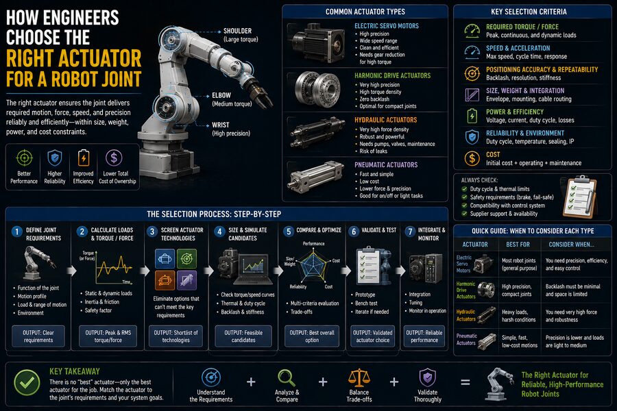
📋 A Typical Actuator Selection Process
A simplified engineering workflow might look like this:
1. 🦾 Determine joint loads
Calculate gravity, payload, inertia, and external forces.
2. 🔄 Determine required motion
Define speed, acceleration, and range of movement.
3. 📊 Calculate torque-speed requirements
Determine continuous and peak conditions.
4. ⚙️ Choose transmission concept
Evaluate direct drive, planetary gearbox, harmonic drive, belt, or other mechanisms.
5. ⚡ Select motor
Match torque, speed, power, voltage, and efficiency.
6. 🌡️ Verify thermal performance
Ensure the actuator survives the real duty cycle.
7. 🎯 Check precision
Evaluate encoders, backlash, stiffness, and control performance.
8. 🪶 Check mass and dimensions
Confirm the actuator fits the robot’s weight and packaging constraints.
9. 🛡️ Evaluate safety
Consider brakes, compliance, force limits, and failure modes.
10. 🧪 Build and test prototypes
Real measurements confirm whether the theoretical design works.
This process may be repeated several times before the final actuator is selected.
🎯 Final Takeaway
Choosing an actuator for a robot joint involves much more than finding a motor with sufficient torque.
Engineers must simultaneously consider torque, speed, power, gearbox ratio, weight, precision, thermal limits, energy efficiency, control performance, safety, and cost. 🤖⚙️
The actuator must be strong enough to move the required load, fast enough to achieve the robot’s motion targets, efficient enough to avoid excessive heat, and compact enough to fit inside the mechanism.
Gearboxes can multiply torque but introduce backlash and friction. Direct-drive motors offer smooth motion but may be heavier. High gear ratios improve torque density but can reduce backdrivability. Powerful motors can generate impressive peak torque but may overheat if that torque is demanded continuously.
The ideal actuator is therefore rarely the one with the largest specification number.
It is the one whose entire operating envelope matches the needs of the joint.
That is why actuator selection is one of the central engineering problems in robotics. Every movement a robot performs—from gently picking up a glass to lifting hundreds of kilograms—ultimately depends on carefully matching electrical power, mechanical design, sensing, and control at each joint. 🦾🔋🎯