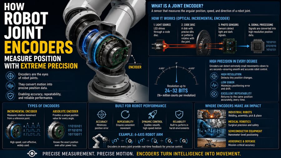

Industrial robots can move with astonishing accuracy. A robotic arm may repeatedly place a component within fractions of a millimeter, weld along the same path thousands of times, or position a camera at an exact angle again and again. This level of precision would be impossible if the robot did not know the exact position of every joint. 🎯⚙️
The devices responsible for measuring those positions are called encoders.
A robot joint encoder converts mechanical rotation or movement into an electrical signal that the robot controller can interpret. By reading those signals continuously, the control system knows how far each motor shaft or joint has moved, how fast it is moving, and in many cases its exact angular position.
The basic process is:
Joint moves ➡️ Encoder detects motion ➡️ Electrical signal is generated ➡️ Controller calculates position ➡️ Motor is corrected if necessary
This closed-loop measurement system allows robots to control their joints with extremely high precision.
🧭 Why Robots Need Joint Position Feedback
Imagine a robotic arm with six rotating joints.
To move its tool to a desired point in space, the controller must know the angle of every joint.
For example:
- Joint 1: 35.2°
- Joint 2: -18.7°
- Joint 3: 62.4°
- Joint 4: 10.1°
- Joint 5: 44.8°
- Joint 6: 92.0°
Using these values and the known geometry of the robot, the controller can calculate where the tool is located.
If even one joint angle is wrong, the final tool position may also be wrong.
Encoders therefore act like the robot’s internal sense of position. 🧠
Humans rely on proprioception to know where their arms and legs are. Robots rely on sensors such as encoders.
⚙️ What Is an Encoder?
An encoder is a device that converts physical movement into a coded electrical output.
In robot joints, encoders usually measure:
- Angular position
- Rotational speed
- Direction of movement
- Number of turns
The encoder may be mounted on:
- The motor shaft
- The gearbox output
- The robot joint itself
Where it is mounted affects what exactly it measures.
An encoder on the motor shaft measures motor rotation, while an encoder after the gearbox may measure the actual joint position more directly.
🔄 Rotary Encoders
Most robot joints rotate, so robots commonly use rotary encoders.
A rotary encoder detects the angular position of a rotating shaft.
If the encoder has very high resolution, it can distinguish extremely small angular movements.
For example, an encoder with 20-bit resolution can divide one full rotation into:
2²⁰ = 1,048,576 positions
Since one full revolution is 360°:
360° / 1,048,576 ≈ 0.000343° per count
That is an extremely small angular increment.
High-end robotic systems may use even greater effective resolution.
📊 Resolution vs. Accuracy
Resolution and accuracy are related but not identical.
🔍 Resolution
Resolution describes the smallest change the encoder can distinguish.
For example:
1,000,000 counts per revolution
means the encoder can divide one rotation into one million increments.
🎯 Accuracy
Accuracy describes how close the reported position is to the true physical position.
An encoder may have extremely high resolution but still contain small measurement errors.
Accuracy can be affected by:
- Manufacturing tolerances
- Shaft misalignment
- Electronic noise
- Temperature
- Mounting errors
- Gearbox behavior
This distinction is important in precision robotics.
🔢 Incremental Encoders
One major encoder type is the incremental encoder.
An incremental encoder produces pulses as the shaft rotates.
The controller counts these pulses.
Suppose the encoder generates:
10,000 counts per revolution
If the controller detects 2,500 counts, the shaft has moved approximately:
2,500 / 10,000 × 360° = 90°
The system determines position by accumulating movement from a known starting point.
🟦 A and B Channels
Incremental encoders often use two pulse signals called:
- Channel A
- Channel B
The signals are offset in phase.
This arrangement is known as quadrature encoding.
By comparing which signal changes first, the controller can determine rotation direction.
For example:
A leads B ➡️ Clockwise
B leads A ➡️ Counterclockwise
This allows the system to track both distance and direction of motion.
🎯 The Index Pulse
Many incremental encoders also provide a third signal called the index pulse, often labeled Z.
This pulse occurs once per revolution.
It provides a known reference position.
During robot startup, the controller may use the index pulse as part of a homing procedure.
Once the reference is found, the robot can begin counting incremental movement from that known location.
🧠 Absolute Encoders
An absolute encoder works differently.
Instead of reporting only movement, it provides a unique code for each angular position.
That means the controller can know the shaft angle immediately after power-up.
For example, an absolute encoder might directly report:
147.362°
without needing to rotate through a reference point first.
This is extremely useful in industrial robots because the arm may contain heavy tooling or be positioned near equipment.
The system ideally should know where the joints are before moving them.
🔐 Why Absolute Position Matters
Suppose a robot loses power during operation.
With a purely incremental system, the controller may lose track of the joint position unless backup measures preserve the count.
The robot might then need to perform a homing procedure.
An absolute encoder can preserve or directly reconstruct its position after power is restored.
This can reduce downtime and improve safety.
🔄 Single-Turn vs. Multi-Turn Absolute Encoders
Absolute encoders can be divided into two broad types.
🔁 Single-Turn Encoder
Reports position within one revolution.
For example:
0° to 360°
🔄 Multi-Turn Encoder
Tracks both:
- Position within a revolution
- Number of complete revolutions
A multi-turn encoder might report something like:
Turn 17 + 132.5°
This is useful when a motor rotates many times to drive a joint through a gearbox.
💡 Optical Encoders
One common precision technology is the optical encoder.
An optical encoder typically contains:
- Light source
- Coded disk
- Photodetectors
- Signal-processing electronics
The disk contains fine transparent and opaque patterns.
As it rotates, light passes through or is blocked by these patterns.
The photodetectors convert the changing light pattern into electrical signals.
Because extremely fine patterns can be manufactured, optical encoders can achieve very high resolution. 🔬
🧲 Magnetic Encoders
Magnetic encoders use magnetic fields instead of light.
A magnet rotates with the shaft.
Sensors detect changes in the magnetic field and determine angular position.
Magnetic encoders can be attractive because they are generally tolerant of:
- Dust
- Oil
- Vibration
- Contamination
These qualities are useful in industrial environments.
Their exact performance depends on design, calibration, magnetic geometry, and signal processing.
⚡ Capacitive and Inductive Encoders
Other encoder technologies use electrical field changes.
Capacitive encoders detect variations in capacitance as patterned elements move relative to each other.
Inductive encoders use electromagnetic coupling.
These technologies can offer good durability and are useful in environments where optical systems may be less suitable.
The choice depends on:
- Required accuracy
- Environmental conditions
- Cost
- Size
- Speed
- Reliability
⚙️ Where Is the Encoder Mounted?
Encoder location is a major design decision.
Suppose a robot joint contains:
Motor ➡️ Gearbox ➡️ Joint
If the encoder is mounted only on the motor, it measures motor rotation.
The controller then estimates joint position using the known gear ratio.
For example:
Motor rotates 100 times ➡️ Joint rotates 1 time
But gearboxes are not perfectly rigid.
They can introduce:
- Backlash
- Elastic deformation
- Gear errors
- Compliance
Therefore, motor position may not exactly equal joint position.
🎯 Output-Side Encoders
Some high-precision robots use an additional encoder at the gearbox output or directly on the joint.
This is called dual-loop feedback in some systems.
One encoder measures the motor.
Another measures the actual joint.
The controller can then compensate for gearbox errors.
This can significantly improve positioning accuracy.
Conceptually:
Motor encoder ➡️ Controls motor motion
Joint encoder ➡️ Measures actual arm position
Together, they provide more precise control.
🔩 Gear Reduction Multiplies Effective Resolution
Robot joints often use gearboxes with large reduction ratios.
Suppose an encoder has:
1,000,000 counts per motor revolution
and the gearbox ratio is:
100:1
The motor rotates 100 times for one joint revolution.
The effective number of encoder counts across one joint revolution becomes:
1,000,000 × 100 = 100,000,000 counts
This can provide extremely fine position measurement.
However, gearbox backlash and elasticity may limit the real mechanical accuracy.
🧮 From Encoder Counts to Joint Angle
The controller must convert encoder readings into meaningful angles.
For an incremental encoder:
Joint angle = Encoder counts × scale factor
If:
Encoder = 65,536 counts per revolution
then:
1 count = 360° / 65,536
The controller continuously updates this calculation.
In real systems, additional factors may include:
- Gear ratio
- Encoder offset
- Joint calibration
- Direction sign
- Mechanical limits
The final joint angle becomes part of the robot’s internal state.
🔄 Closed-Loop Servo Control
Encoders are essential to servo control.
A servo system compares desired position with measured position.
Suppose the controller commands:
Desired joint angle = 45.000°
The encoder reports:
Actual joint angle = 44.982°
The error is:
45.000° – 44.982° = 0.018°
The controller commands the motor to move slightly farther.
The loop repeats:
Command ➡️ Measure ➡️ Compare ➡️ Correct ➡️ Measure again
This can happen thousands of times per second. ⚡
🎛️ PID Control
Many servo systems use control algorithms based on PID control.
PID stands for:
- Proportional
- Integral
- Derivative
The controller uses position error and motion behavior to calculate motor torque or current.
The encoder provides the feedback required for the calculation.
Without accurate encoder information, even a sophisticated controller would not know whether the motor actually reached its commanded position.
🏎️ Encoders Also Measure Speed
Position measurements can also be used to estimate velocity.
If the encoder position changes by:
Δθ
during a short interval:
Δt
then approximate angular velocity is:
ω = Δθ / Δt
The controller can therefore determine how quickly the joint is moving.
High-resolution encoders produce smoother and more precise velocity estimates, especially at low speeds.
🚀 Measuring Acceleration
Acceleration can be estimated from changes in velocity.
This allows the robot controller to monitor:
- Position
- Speed
- Acceleration
Together, these measurements help produce smooth motion.
Robots often follow carefully planned motion profiles rather than instantly jumping from one speed to another.
Encoder feedback confirms whether the real joint follows the planned trajectory.
🎯 Why Tiny Angular Errors Matter
A small joint angle error can become a significant tool-position error.
Imagine a robot arm segment that is:
1 meter long
An angular error of only:
0.1°
can shift the endpoint by roughly:
1.7 millimeters
depending on geometry.
In precision assembly, 1.7 mm may be unacceptable.
This is why industrial robots need highly accurate joint sensing and careful calibration.
🦾 Forward Kinematics
Robot controllers use a mathematical method called forward kinematics.
Forward kinematics calculates the position and orientation of the robot tool from the measured joint angles.
Conceptually:
Joint 1 angle + Joint 2 angle + Joint 3 angle + … ➡️ Tool position
The encoder readings are therefore the foundation of the robot’s understanding of its own geometry.
If encoder values are wrong, the calculated tool location will also be wrong.
📍 Calibration Improves Accuracy
Even excellent encoders do not automatically guarantee perfect robot accuracy.
Mechanical tolerances can cause small differences between the theoretical robot geometry and the actual machine.
Calibration procedures may measure:
- Joint zero offsets
- Link lengths
- Axis alignment
- Gear errors
These corrections are stored in the controller.
Then:
Raw encoder reading ➡️ Calibration correction ➡️ More accurate joint position
High-end robotics depends heavily on this calibration process.
🌡️ Temperature Can Change Precision
Robot components expand and contract with temperature.
A gearbox, shaft, bearing, or encoder mount may change dimensions slightly as it warms.
For ordinary motion, these changes may be insignificant.
For very high-precision applications, they can matter.
Some systems use temperature compensation models or stable materials to reduce thermal errors.
🧱 Mechanical Backlash
Backlash is a small amount of free movement between mechanical components.
Suppose a motor reverses direction.
The motor shaft may rotate slightly before the output gear fully engages in the opposite direction.
If only the motor encoder is measured, the controller may believe the joint has already begun moving.
A direct joint encoder can detect that the actual joint has not yet moved.
This is another advantage of output-side sensing.
🌀 Elastic Deformation
Robots are not perfectly rigid.
Under heavy loads, components can flex.
For example:
Motor position says 30.000°
but the gearbox and link may deform slightly under torque.
The actual arm position could differ.
Advanced robots may use additional joint encoders, torque sensors, or structural models to compensate for this flexibility.
📡 Digital Communication
Modern absolute encoders often communicate digitally with the robot controller.
Instead of sending only analog pulses, they may transmit structured position data.
Digital interfaces can provide:
- Position
- Status
- Diagnostic information
- Error flags
- Temperature data
Some systems use high-speed serial communication so precise position information can be updated rapidly.
🔐 Error Detection
Industrial robot encoders may contain diagnostic features.
The controller can detect issues such as:
- Invalid position codes
- Communication errors
- Signal loss
- Power failure
- Excessive disagreement between sensors
If the feedback becomes unreliable, the robot may stop rather than continue moving blindly.
This is especially important around human workers and expensive machinery.
🛑 Safety Encoders
Some collaborative and safety-rated robots use redundant sensing.
Two independent position measurements may monitor the same joint.
The safety controller compares them.
If:
Encoder A ≠ Encoder B beyond allowed tolerance
the system can trigger a safe stop.
Redundancy reduces the chance that a single sensor failure creates dangerous uncontrolled movement.
🏭 Encoders in Industrial Robot Applications
Precision encoders are essential in many applications.
🔩 Assembly
A robot may insert tiny components into precisely located holes.
🔥 Welding
The tool must follow the same seam accurately.
🎨 Painting
Smooth joint motion creates consistent coating thickness.
📦 Pick and Place
The robot must repeatedly reach exact coordinates.
🔬 Electronics Manufacturing
Tiny components may require sub-millimeter positioning.
Without accurate joint encoders, these applications would be far less reliable.
🧪 Encoders in Surgical and Laboratory Robots
Precision becomes even more critical in medical or laboratory robotics.
A surgical robot may need extremely controlled movements.
A laboratory robot may position pipettes over very small containers.
In these systems, joint sensing works together with:
- Force sensors
- Vision systems
- Calibration models
- Safety controls
Encoders provide the fundamental mechanical position feedback.
👁️ Encoders and Vision Work Together
Robot vision systems can detect where objects are in the external environment.
Encoders tell the robot where its own joints are.
The two forms of sensing complement each other.
Conceptually:
Camera ➡️ Where is the object?
Encoder ➡️ Where is the robot?
The controller combines these measurements to guide the tool toward the correct target.
🧠 Example: A Robot Moving to 90 Degrees
Suppose a robot joint is currently at:
30.000°
The controller commands:
90.000°
The sequence might be:
- 🎯 Controller calculates the target.
- ⚡ Motor receives torque command.
- ⚙️ Joint begins rotating.
- 🔍 Encoder continuously measures position.
- 📈 Controller monitors speed and error.
- 🐢 Motor slows as it approaches 90°.
- 🎯 Encoder reports 89.995°.
- ⚙️ Controller makes a tiny correction.
- ✅ Encoder reports approximately 90.000°.
- 🔒 Servo maintains the position against disturbances.
This is the essence of precision robot motion.
⚠️ High Resolution Does Not Guarantee High Robot Accuracy
It is tempting to assume that an encoder with millions of counts automatically creates an ultra-accurate robot.
But overall robot accuracy also depends on:
- Structural stiffness
- Gearbox precision
- Calibration
- Temperature
- Load
- Bearing quality
- Controller tuning
- Manufacturing tolerances
The encoder is one part of a larger precision system.
However, without high-quality position feedback, the controller would have no reliable way to correct many of these errors.
🌟 The Bigger Picture
Robot joint encoders give machines an extremely precise internal sense of where their moving parts are located.
They transform tiny mechanical rotations into electrical or digital measurements that the controller can interpret.
The complete process is:
Joint movement ⚙️ ➡️ Encoder measurement 🔍 ➡️ Position data 🔢 ➡️ Controller comparison 🧠 ➡️ Motor correction ⚡ ➡️ Precise motion 🎯
Incremental encoders track movement using pulses, while absolute encoders provide unique position values.
Optical, magnetic, capacitive, and inductive technologies offer different combinations of precision, durability, speed, and environmental resistance.
High-resolution encoders may divide one revolution into hundreds of thousands or millions of measurable positions. Gear reduction can make the effective joint resolution even finer.
But the true power comes from closed-loop control.
The robot does not simply assume that a motor moved correctly. It continuously measures the real position, compares it with the desired position, and corrects any error.
This feedback happens repeatedly at very high speed.
That is why a robot arm weighing hundreds of kilograms can place a tool with extraordinary repeatability.
Encoders effectively provide the robot with a finely detailed internal coordinate system—one that allows every joint to know where it is, where it is going, and whether it has reached exactly the position the controller requested. 🤖📐⚙️