The trend in surgical robots is moving from traditional master-slave robots to miniaturized devices for screening and simple surgical operations (Cuschieri, A. 2005). For example, capsule endoscopy (Moglia, A. 2007) has been conducted worldwide over the last five years with successful outcomes. To enhance the dexterity of commercial endoscopic capsules, capsule locomotion has been investigated using legged capsules (Quirini, M. 2008) and capsules driven by external magnetic fields (Sendoh, M. 2003; Ciuti, G. 2010; Carpi, F. 2009). Endoscopic capsules with miniaturized arms have also been studied to determine their potential for use in biopsy (Park, S.-K. 2008). Furthermore, new surgical procedures known as natural orifice transluminal endoscopic surgery (NOTES) and Single Port Access surgery are accelerating the development of innovative endoscopic devices (Giday, S. 2006; Bardaro, S.J. 2006). These advanced surgical devices show potential for the future development of minimally invasive and endoluminal surgery. However, the implementable functions in such devices are generally limited owing to space constraints. Moreover, advanced capsules or endoscopes with miniaturized arms have rather poor dexterity because the diameter of such arms must be small (i.e. a few millimeters), which results in a small force being generated at the tip.
A modular surgical robotic system known as the ARES (Assembling Reconfigurable Endoluminal Surgical system) system has been proposed based on the aforementioned motivations (Harada, K. 2009; Harada, K. 2010; Menciassi, A. 2010). The ARES system is designed for screening and interventions in the gastrointestinal (GI) tracts to overcome the intrinsic limitations of single-capsules or endoscopic devices. In the proposed system, miniaturized robotic modules are ingested and assembled in the stomach cavity. The assembled robot can then change its configuration according to the target location and task. Modular surgical robots are interesting owing to their potential for application as self- reconfigurable modular robots and innovative surgical robots. Many self-reconfigurable modular robots have been investigated worldwide (Yim, M. 2007; Murata, S. 2007) with the goal of developing systems that are robust and adaptive to the working environment. Most of these robots have been designed for autonomous exploration or surveillance tasks in unstructured environments; therefore, there are no strict constraints regarding the number of modules, modular size or working space. Because the ARES has specific applications and is used in the GI tract environment, it raises many issues that have not been discussed in depth in the modular robotic field. Modular miniaturization down to the ingestible size is one of the most challenging goals. In addition, a new interface must be developed so that surgeons can intuitively maneuver the modular surgical robot.
The purpose of this paper is to clarify the advantages of the modular approach in surgical applications, as well as to present proof of concept of the modular robotic surgical system. The current paper is organized as follows: Section 2 describes the design of the ARES system. Section 3 details the design and prototyping of robotic modules, including the experimental results. Section 4 describes a reconfigurable master device designed for the robotic modules, and its preliminary evaluation is reported.
Design of the modular surgical system
Clinical indications and proposed procedures
The clinical target of the ARES system is the entire GI tract, i.e., the esophagus, stomach, small intestine, and colon. Among GI tract pathologies that can benefit from modular robotic features, biopsy for detection of early cancer in the upper side of the stomach (the fundus and the cardia) was selected as the surgical task to be focused on as a first step. Stomach cancer is the second leading cause of cancer-related deaths worldwide (World Health Organization 2006), and stomach cancer occurring in the upper side of the stomach has the worst outcome in terms of the 5-year survival ratio (Pesic, M. 2004). Thus, early diagnosis of cancer utilizing an advanced endoluminal device may lead to better prognosis. The stomach has a large volume (about 1400 ml) when distended, which provides working space to assemble the ingested robotic modules and change the topology of the assembled robot inside (i.e. reconfiguration). Each robotic module should be small enough to be swallowed and pass through the whole GI tract. Because the size of the commercial endoscopic capsules (11 mm in diameter and 26 mm in length (Moglia, A. 2007)) has already been shown to be acceptable for the majority of patients as an ingestible device, each module needs to be miniaturized to this size before being applied to clinical cases.
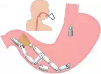
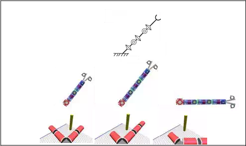
The surgical procedures proposed for the ARES system (Harada, K. 2010) are shown in Fig.
1. Prior to the surgical procedure, the patient drinks a liquid to distend the stomach to a volume of about 1400 ml. Next, the patient ingests 10-15 robotic modules that complete the assembly process before the liquid naturally drains away from the stomach in 10-20 minutes. The number of the modules swallowed depends on the target tasks and is determined in advance based on the pre-diagnosis. Magnetic self-assembly in the liquid using permanent magnets was selected for this study since its feasibility has already been demonstrated (Nagy, Z. 2007). Soon after the assembly, the robot configures its topology according to preoperative planning by repeated docking and undocking of the modules (the undocking mechanism and electrical contacts between modules are necessary for reconfiguration, but they have not been implemented in the presented design). The robotic modules are controlled via wireless bidirectional communication with a master device operated by the surgeon, while the progress in procedure is observed using intraoperative imaging devices such as fluoroscopy and cameras mounted on the modules. After the surgical tasks are completed, the robot reconfigures itself to a snake-like shape to pass through the pyloric sphincter and travel to examine the small intestine and the colon, or it completely disassembles itself into individual modules so that it can be brought out without external aid. One of the modules can bring a biopsy tissue sample out of the body for detailed examination after the procedure is complete.
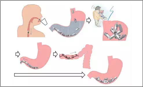
Fig. 1. Proposed procedures for the ARES system
Advantages of the modular approach in surgical applications
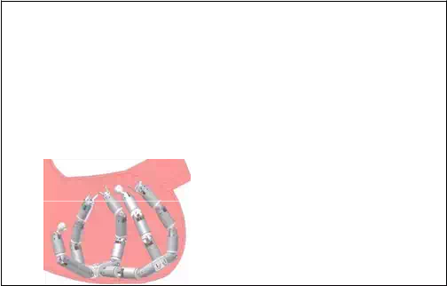
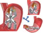
The modular approach has great potential to provide many advantages to surgical applications. These advantages are summarized below using the ARES system as shown in Fig.2. The numbering of the items in Fig.2 is correlated with the following numbering.
i. The topology of the modular surgical robot can be customized for each patient according to the location of the disease and the size of the body cavity in which the modular robot is deployed. A set of functional modules such as cameras, needles and forceps can be selected for each patient based on the necessary diagnosis and surgical operation.
ii. The modular approach facilitates delivery of more components inside a body cavity that has small entrance/exit hole(s). As there are many cavities in the human body, the modular approach would benefit treatment in such difficult-to-reach places. Because several functional modules can be used simultaneously, the modular robot may perform rather complicated tasks that a single endoscopic capsule or an endoscopic device is not capable of conducting. For example, if more than two camera modules are employed, the surgeon can conduct tasks while observing the site from different directions.
iii. Surgical tools of relatively large diameter can be brought into the body cavity.
Conventionally, small surgical forceps that can pass through an endoscopic channel of a few millimeters have been used for endoluminal surgery. Conversely, surgical devices that have the same diameter as an endoscope can be used in the modular surgical system. Consequently, the force generated at the tip of the devices would be rather large, and the performance of the functional devices would be high.
iv. The surgical system is more adaptive to the given environment and robust to failures.
Accordingly, it is not necessary for the surgical robot to equip all modules that might be necessary in the body because the surgeons can decide whether to add modules with different functionalities, even during the surgical operation. After use, the modules can be detached and discarded if they are not necessary in the following procedures. Similarly, a module can be easily replaced with a new one in case of malfunction.
As these advantages suggest, a modular surgical robot would be capable of achieving rather complicated tasks that have not been performed using existing endoluminal surgical devices. These advantages are valid for modular robots that work in any body cavity with a small entrance and exit. Moreover, this approach may be introduced to NOTES or Single Port Access surgery, in which surgical devices must reach the abdominal cavity through a small incision.
In Section 3, several robotic modules are proposed, and the performance of these modules is reported to show the feasibility of the proposed surgical system.
 (i)
(i)
(ii)
(iii)

 (iv)
(iv)
Fig. 2. Advantages of the modular approach in surgical applications
Robotic modules
Design and prototyping of the robotic modules
Figure 3 shows the design and prototypes of the Structural Module and the Biopsy Module (Harada, K. 2009, Harada, K. 2010). The Structural Module has two degrees of freedom (±90° of bending and 360° of rotation). The Structural Module contains a Li-Po battery (20 mAh, LP2-FR, Plantraco Ltd., Canada), two brushless DC geared motors that are 4 mm in diameter and 17.4 mm in length (SBL04-0829PG337, Namiki Precision Jewel Co. Ltd., Japan) and a custom-made motor control board capable of wireless control (Susilo, E. 2009). The stall torque of the selected geared motor is 10.6 mNm and the speed is 112 rpm when controlled by the developed controller. The bending mechanism is composed of a worm and a spur gear (9:1 gear reduction), whereas the rotation mechanism is composed of two spur gears (no gear reduction). All gears (DIDEL SA, Switzerland) were made of nylon, and they were machined to be implemented in the small space of the capsule. Two permanent magnets (Q-05-1.5-01-N, Webcraft GMbH, Switzerland) were attached at each end of the module to help with self-alignment and modular docking. The module is 15.4 mm in diameter and 36.5 mm in length; it requires further miniaturization before clinical application. The casing of the prototype was made of acrylic plastic and fabricated by 3D rapid prototyping (Invison XT 3-D Modeler, 3D systems, Inc., USA). The total weight is 5.6 g. Assuming that the module would weigh 10 g with the metal chassis and gears, the maximum torque required for lifting two connected modules is 5.4 mNm for both the bending DOF and rotation DOF. Assuming that the gear transmission efficiency for the bending mechanism is 30%, the stall torque for the bending DOF is 28.6 mNm. On the other hand, the stall torque for the rotation DOF is 8.5 mNm when the transmission efficiency for the rotation mechanism is 80%. The torque was designed to have sufficient force for surgical operation, but the transmission efficiency of the miniaturized plastic gears was much smaller than the theoretical value as explained in the next subsection.
• Controller
The aforementioned brushless DC motor came with a dedicated motor driving board (SSD04, Namiki Precision Jewel Co., Ltd., 19.6 mm × 34.4 mm × 3 mm). This board only allows driving of one motor; hence, two boards are required for a robotic module with 2
DOFs. Because there was not sufficient space for the boards in the robotic module, a custom made high density control board was designed and developed in-house. This control board consisted of one CC2430 microcontroller (Texas Instrument, USA) as the main wireless controller and three sets of A3901 dual bridge motor drivers (Allegro MicroSystem, Inc., USA). The fabricated board is 9.6 mm in diameter, 2.5 mm in thickness and 0.37 g in weight, which is compatible with swallowing. The A3901 motor driver chip was originally intended for a brushed DC motor, but a software commutation algorithm was implemented to control a brushless DC motor as well. An IEEE 802.15.4 wireless personal area network (WPAN) was introduced as an embedded feature (radio peripheral) of the microcontroller. The implemented algorithm enables control of the selected brushless DC motor in Back Electro- Motive Force (BEMF) feedback mode or slow speed stepping mode. When the stepping mode is selected, the motor can be driven with a resolution of 0.178º.
For the modular approach, each control board shall be equipped with a wired locating system for intra-modular communication in addition to the wireless communication. Aside from wireless networking, the wired locating system, which is not implemented in the presented design, would be useful for identification of the sequence of the docked modules in real time. The wired locating system is composed of three lines, one for serial multidrop communication, one for a peripheral locator and one as a ground reference. When the modules are firmly connected, the intra-modular communication can be switched from wireless to wired to save power while maintaining the predefined network addresses. When one module is detached intentionally or by mistake, it will switch back to wireless mode.
• Battery
The battery capacity carried by each module may differ from one to another (e.g. from 10 mAh to 50 mAh) depending on the available space inside the module. For the current design, a 20 mAh Li-Po battery was selected. Continuous driving of the selected motor on its maximum speed using a 20 mAh Li-Po battery was found to last up to 17 minutes. A module does not withdraw power continuously because the actuation mechanisms can maintain their position when there is no current to the motor owing to its high gear reduction (337:1). A module consumes power during actuation, but its power use is very low in stand-by mode.
• Biopsy Module
The Biopsy Module is a Functional Module that can be used to conduct diagnosis. The grasping mechanism has a worm and two spur gears, which allows wide opening of the grasping parts. The grasping parts can be hidden in the casing at the maximum opening to prevent tissue damage during ingestion. The motor and other components used for the Biopsy Module are the same as for the Structural Module. The brushless DC geared motors (SBL04-0829PG337, Namiki Precision Jewel Co. Ltd., Japan), the control board, a worm gear and two spur gears (9:1 gear reduction) were implemented in the Biopsy Module. A permanent magnet (Q-05-1.5-01-N, Webcraft GMbH, Switzerland) was placed at one side to be connected to another Structural Module.

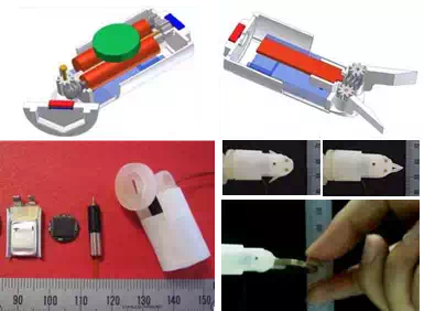
Fig. 3. Design and prototypes of the structural module (left) and the biopsy module (right)
The Biopsy Module can generate a force of 7.1 N at its tip, and can also open the grasping parts to a width of 19 mm with an opening angle of 90 degrees. These values are much larger than those of conventional endoscopic forceps, which are 2-4 mm in diameter. As a demonstration, Figure 3 shows the Biopsy Module holding a coin weighing 7.5 g.
In conventional endoscopy, forceps are inserted through endoscopic channels that are parallel to the direction of the endoscopic view, which often results in the forceps hiding the target. Conversely, the Biopsy Module can be positioned at any angle relative to the endoscopic view owing to the modular approach, thereby allowing adequate approach to the target.
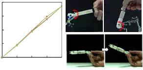
Performance of the Structural Module
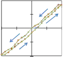
The mechanical performance of the bending and rotation DOFs of the Structural Module was measured in preliminary tests (Menciassi, A. 2010), and the results are summarized in Fig.4. The bending angle was varied by up to ± 90° in steps of 10° three times in succession. The measured range of the bending angle was -86.0° to +76.3°, and the maximum error was
15.8°. The rotation angle was increased from 0° to 180° in steps of 45° three times in succession, and the measured range of the rotational angle was between 0° and 166.7° with a maximum error of 13.3°. The difference between the driven angle and the measured angle was due to backlash of the gears and the lack of precision and stiffness of the casing made by 3D rapid prototyping. Regardless of the errors and the hysteresis, the repeatability was sufficient for the intended application for both DOFs. These results indicate that the precision of each motion can be improved by changing the materials of the gears and the casing. Since the motor can be controlled with a resolution of 0.178°, very precise surgical tasks can be achieved using different manufacturing processes.
 90 180
![]() 45 135
45 135
![]() 0 90
0 90
-45 45
–90
–90
-45 0
45 90 0
 45 90
45 90
135
 180
180
Commanded Angle (deg.)
Commanded Angle (deg.)

Fig. 4. Bending angle measurement (left), rotation angle measurement (middle), and torque measurement (right) (Menciassi, A. 2010)
In addition to the angle measurements, both bending and rotation torque were measured. The torque was measured by connecting cylindrical parts with permanent magnets at both ends until the bending/rotational motion stopped. The length and weight of each cylinder was designed in advance, and several types of cylinders were prepared. The measured bending torque was 6.5 mNm and the rotation torque was 2.2 mNm. The figure also shows one module lifting up two modules attached to its bending mechanism as a demonstration. The performance in terms of precision and generated torque, which are very important for reconfiguration and surgical tasks, was sufficient; however, the precision was limited owing to the aforementioned fabrication problems. The thin walls of the casing made of acrylic plastic were easily deformed, which caused friction between the parts. The casing made of metal or PEEK and tailor-made metal gears with high precision will improve the mechanism rigidity and performance, thus producing the optimal stability.
Possible designs of robotic modules
Figure 5 shows various designs of robotic modules that can be implemented in the modular surgical robot. The modules can be categorized into three types: structural modules, functional modules, and other modules. Structural modules are used to configure a robotic topology. Functional modules are used for diagnosis or intervention, while other modules can be added to enhance the performance and robustness of the robotic system. Obviously, an assembled robot made of different types of modules (i.e. a robot with high heterogeneity) may provide high dexterity, but the self-assembly in the stomach and control of the modules would become more difficult. To optimize the level of heterogeneity, self-assembly of the robotic modules must be developed so that the reconfiguration of the robotic topology following the self-assembly can be planned in advance. Employing pre-assembled modular arms or tethered modules can be another option to facilitate assembly in a body cavity; however, this would require further anesthesia, and it would hinder the promotion of massive screening.

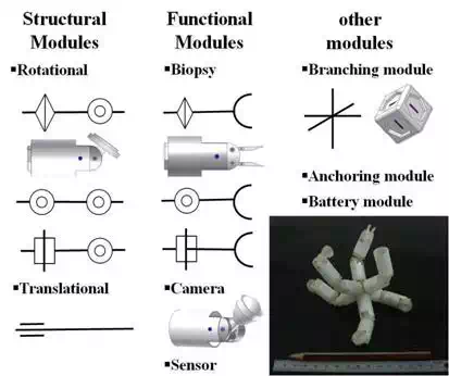
Fig. 5. Various designs of the robotic modules
Reconfigurable master device
Design and prototyping of the reconfigurable master device
One main advantage of using a modular approach in surgical applications is the adaptivity to the given environment as mentioned in Section 2.2. Wherever the robotic platform is deployed in the GI tract, the robotic topology can be changed based on preoperative plans or the in-situ situation to fit in any particular environment. This dynamic changing and reshaping of the robotic topology should be reflected on the user interface. Since it is possible for a robotic topology to have redundant DOFs, the master device for the modular surgical system needs to be able to handle the redundancy that is inherent to modular robots. Based on these considerations, we propose a reconfigurable master device that resembles the robotic platform (Fig.6). When the assembled robot changes its topology, the master device follows the same configuration. The robotic module shown in Fig. 6 has a diameter of 15.4 mm, while a module of the reconfigurable master device has a diameter of 30 mm. The master modules can be easily assembled or disassembled using set screws, and it takes only a few seconds to connect one module to another.
Each robotic module is equipped with two motors as described in the previous section; thus, each master module is equipped with two potentiometers (TW1103KA, Tyco Electronics) that are used as angular position sensors. Calculating the angular position of each joint of the reconfigurable master device is quite straightforward. A common reference voltage is sent from a data acquisition card to all potentiometers, after which the angular position can be calculated from the feedback readings. Owing to the identical configuration, the angle of each joint of the robotic modules can be easily determined, even if the topology has redundancy.
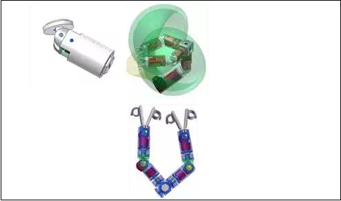
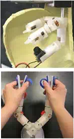
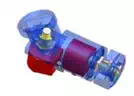
Fig. 6. Robotic modules (top line) and the reconfigurable master device (bottom line): one module (left), assembled modules (middle) and prototypes (right)
The advantages of the proposed master device include intuitive manipulation. For example, the rotational movement of a structural module used to twist the arm is limited to ± 180°, and the master module also has this limitation. This helps surgeons intuitively understand the range of the motion and the reachable working space of the modules. Using a conventional master manipulator or an external console, it is possible that the slave manipulator cannot move owing to its mechanical constraints, while the master manipulator can still move. However, using the proposed master device, the surgeon can intuitively understand the mechanical constraints by manipulating the master device during practice/training. Furthermore, the position of the master arm can indicate where the robotic modules are, even if they are outside of the camera module’s view. These characteristics increase the safety of the operation. This feature is important because the entire robotic system is placed inside the body. In other surgical robotic systems, the position or shape of the robotic arms is not important as they are placed outside of the body and can be seen during operation. Unlike other master devices, it is also possible for two or more surgeons to move the reconfigurable master device together at the same time using multi arms with redundant DOFs.
Evaluation
A simulation-based evaluation setup was selected to simplify the preliminary evaluation of the feasibility of the reconfigurable master device. The authors previously developed the Slave Simulator to evaluate workloads for a master-slave surgical robot (Kawamura, K.2006). The Slave Simulator can show the motion of the slave robot in CG (Computer Graphics), while the master input device is controlled by an operator. Because the simulator can virtually change the parameters of the slave robot or its control, it is easy to evaluate the parameters as well as the operability of the master device. This Slave Simulator was appropriately modified for the ARES system. The modified Slave Simulator presents the CG models of the robotic modules to the operator. The dimension and DOFs of each module in CG were determined based on the design of the robotic modules. The angle of each joint is given by the signal from the potentiometers of the reconfigurable master device, and the slave modules in CG move in real time to reproduce the configuration of the master device. This Slave Simulator is capable of altering joint positions and the number of joints of the slave arms in CG so that the workspace of the reconfigurable master device can be reproduced in a virtual environment for several types of topologies. The simulator is composed of a 3D viewer that uses OpenGL and a physical calculation function. This function was implemented to detect a collision between the CG modules and an object placed in the workspace.
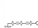
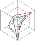
To simplify the experiments to evaluate the feasibility of the proposed master device and usefulness of the developed simulator, only one arm of the reconfigurable master device was used. Three topologies that consist of one Biopsy Module and one or two Structural Module(s) were selected as illustrated in Fig.7. Topology I consists of a Structural Module and a Biopsy Module, and the base is fixed so that the arm appears with an angle of 45 degrees. One Structural Module is added to Topology I to configure Topology II, and Topology III is identical to Topology II, but placed at 0 degrees. Both Topology II and Topology III have redundant DOFs. The projection of the workspace of each arm and the shared workspace are depicted in Fig.8. A target object on which the arm works in the experiments must be placed in this shared area, which makes it easy to compare topologies.
A bar was selected as the target object instead of a sphere because the height of the collision point is different for each topology when the object appears in the same position in the 2D plane.
The experiment was designed so that a bar appears at random in the shared workspace. The bar represents a target area at which the Biopsy Module needs to collect tissue samples, and this experiment is a simple example to select one topology among three choices given that the arm can reach the target. We assumed that this choice may vary depending on the user, and this experiment was designed to determine if the reconfigurability of the master device, i.e. customization of the robot, provides advantages and improves performance.

 Combination
 Master device
Simulator
Topology I Topology II Topology III
Fig. 7. Three topologies used in the experiments
During the experiment, the operator of the reconfigurable master device could hear a beeping sound when the distal end of the arm (i.e. the grasping part of the biopsy module) touched the bar. The task designed for the experiments was to move the arm of the reconfigurable master device as quickly as possible, touch the bar in CG, and then maintain its position for three seconds. The plane in which the bar stands is shown in grids (Fig.9), and the operator obtains 3D perception by observing these grids. The plane with the grids is the same for all topologies. The angle of the view was set so that the view is similar to that from the camera module in Fig.6.
Five subjects (a-e) participated in the experiments, none of whom were surgeons. Each subject was asked to freely move the master device to learn how to operate it; however, this practice was allowed for one minute before starting the experiments. Each subject started from Topology I, then tested Topology II and finally Topology III. The time needed to touch the bar and maintain it for three seconds was measured. This procedure was repeated ten times for each topology with a randomized position of the bar. During the procedure, the bar appeared at random; however, it always appeared in the shared workspace to ensure that the arm could reach it. After finishing the experiment, the subjects were asked to fill in a questionnaire (described below) for each topology. The subjects were also asked which topology they preferred.
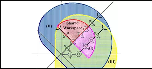
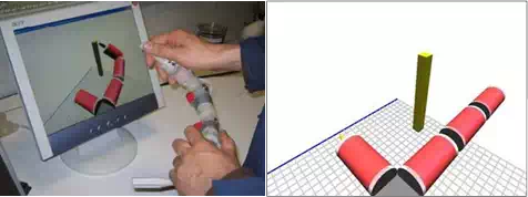
 Fig. 8. Workspace of each topology and the shared workspace
Fig. 9. Simulator and the master device during one test
A NASA TLX questionnaire (NASA TLX (website)) was used to objectively and quantitatively evaluate the workload that the subjects felt during the experiments. This method has versatile uses, and we selected this method also because it was used to evaluate the workload in a tele-surgery environment (Kawamura, K. 2006). This method evaluates Metal Demand, Physical Demand, Temporal Demand, Performance, Effort and Frustration, and gives a score that represents the overall workload that the subject felt during the task.
Results
The time spent conducting the given task, the workload score evaluated using the NASA TLX questionnaire and the preference of the topology determined by the subjects are summarized in Table 1. For each item, a smaller value indicates a more favorable evaluation by the subject.
Considering the results of the time and workload score, Topology II was most difficult. The difference between Topology I and III was interesting. Two of the subjects ((b) and (c)) preferred Topology I, which did not have a redundant DOF. Conversely, three of the subjects ((a), (d) and (e)) preferred Topology III because they could select the path to reach the target owing to the redundant DOF. The average scores of the NASA TLX parameters shown in Fig.10 suggest that the Physical Demand workload was high for Topology I, while the Effort workload was high for Topology III.
![]() The two subjects who preferred Topology I rather than Topology III claimed that it was not easy to determine where the bar was located when Topology III was used owing to the lack of 3D perception. In addition, they reported that the bar seemed to be placed far from the base. However, the bar appeared randomly, but in the same area; therefore, the bar that appeared in the experiment that employed Topology III was not placed farther from the base when compared to the experiments that used Topology I or Topology II. Accordingly, these two subjects may have had difficulty obtaining 3D perception from the gridded plane. In Topology III, the arm was partially out of view in the initial position; thus, the operator needed to obtain 3D perception by seeing the grids. It is often said that most surgeons can obtain 3D perception even if they use a 2D camera, and our preliminary experimental results imply that this ability might differ by individual. Some people appear to obtain 3D perception primarily by seeing the relative positions between the target and the tool they move. Redundant DOFs may also be preferred by operators with better 3D perception capability. Although the experiments were preliminary, there must be other factors that accounted for the preference of the user. Indeed, it is likely that the preferable topology varies depending on the user, and the developed simulator would be useful to evaluate these variations. The proposed reconfigurable master device will enable individual surgeons to customize the robot and interface as they prefer.
The two subjects who preferred Topology I rather than Topology III claimed that it was not easy to determine where the bar was located when Topology III was used owing to the lack of 3D perception. In addition, they reported that the bar seemed to be placed far from the base. However, the bar appeared randomly, but in the same area; therefore, the bar that appeared in the experiment that employed Topology III was not placed farther from the base when compared to the experiments that used Topology I or Topology II. Accordingly, these two subjects may have had difficulty obtaining 3D perception from the gridded plane. In Topology III, the arm was partially out of view in the initial position; thus, the operator needed to obtain 3D perception by seeing the grids. It is often said that most surgeons can obtain 3D perception even if they use a 2D camera, and our preliminary experimental results imply that this ability might differ by individual. Some people appear to obtain 3D perception primarily by seeing the relative positions between the target and the tool they move. Redundant DOFs may also be preferred by operators with better 3D perception capability. Although the experiments were preliminary, there must be other factors that accounted for the preference of the user. Indeed, it is likely that the preferable topology varies depending on the user, and the developed simulator would be useful to evaluate these variations. The proposed reconfigurable master device will enable individual surgeons to customize the robot and interface as they prefer.
| TopologySubject abcde I5.74.14.05.85.04.9II7.66.24.85.56.76.1III4.94.35.64.44.74.8I30.711.328.332.073.335.1II47.626.728.053.068.344.7III37.05.024.314.361.328.4I311332.2II232222.2III123111.6 |
Average
![]()
![]() Time (s)
Time (s)
![]() Work Load: NASA-TLX Score
Work Load: NASA-TLX Score
![]() Preference
Preference
Table 1. Experimental results
Frustration
Effort
Mental
Demand
 15
15
10
5
 0
0
Physical
![]()
![]()
![]()
![]()
![]() Demand
Demand
Temporal
Demand
Topology I Topology II Topology III
Performance
Fig. 10. NASA TLX parameters for three topologies
Conclusion
A modular robot was proposed for endoluminal surgery. The design, prototyping and evaluation of the modules were reported. Although there are some issues related to the fabrication problems, the results of the performance tests show the feasibility of the modular surgical system. A reconfigurable master device has also been proposed, and its feasibility was evaluated by simulation-based experiments. The preliminary results showed that the preferred topology may vary depending on the user. Moreover, the reconfigurable master device would enable each surgeon to customize the surgical system according to his/her own preferences. Development of the robotic modules and the reconfigurable master device provided proof of concept of the modular robotic system for endoluminal surgery, suggesting that the modular approach has great potential for surgical applications.

Comments are closed