We focus on grasp planning for a humanoid multi-fingered hand attached at the tip of a humanoid robot’s arm. The hand has potential possibility to grasp various objects under several situations. Since the multi-fingered hand can use several grasp types such as fingertip grasp, and envelope grasp with taking the advantage of degrees of freedom. We develop grasp planner which selects a feasible grasp type based on the task, and determines contact positions for the fingers and the grasped object surface so that the fingers do not drop the object while staying with limited actuator capacity.
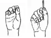
To grasp an object, the robot first measures object position/orientation using vision sensor. Then, the planner plans the body motion to complete the grasping task based on vision sensor information. Even when the object’s location is not known beforehand, the robot should complete the grasping task as fast as possible. However, grasp planning with a humanoid robot is complex and often requires long calculation time. Hence, for the grasp planning, a heuristic but fast algorithm is preferred rather than precise but slow algorithms (Shimoga (1989)). Our planner calculates grasp motions within reasonable time by using predefined grasp types which are assigned with contacting finger links, desired sizes of the grasped object. Our planner selects a grasp type according to position/orientation of the grasped object similar to a human. As shown in Fig. 1 , a human grasps the side of the can with all fingers, grasps the top with fewer fingers.
Failing to find feasible grasping posture using arm/hand kinematics alone, our planner attempts to do so using the full body kinematics. Using the degrees of freedom of full body, the planner has adaptable for reaching the object with the several motions such as twisting waist, bending waist, and squatting down.
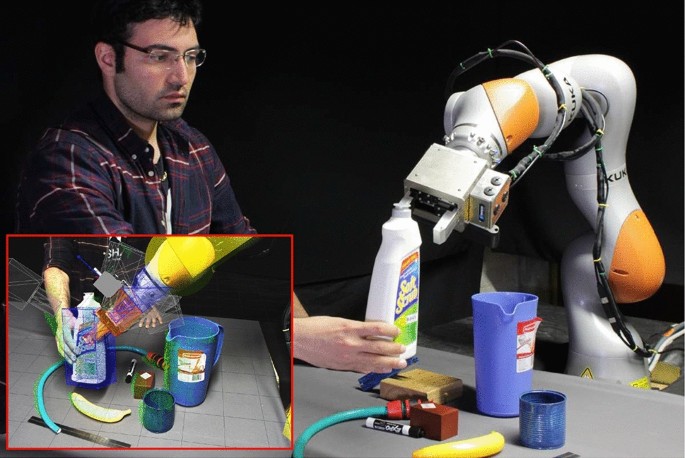
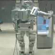
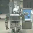
We demonstrate effectiveness of grasp planning through simulation and experimental results by using humanoid robot HRP-3P (Akachi et al. (2005)) shown in Fig. 2, which has a four-fingered hand HDH (Kaneko et al. (2007)) on its right-arm and a stereo camera system in
its head.
We has proposed the grasp planning which was executed within the reasonable time taking into account several constraints imposed on the system such as the feasible grasping style, the friction cone constraint at each contact point, the maximum contact force applied by the fingers, the inverse kinematics of the arm and the fingers (Harada et al. (2008); Tsuji et al. (2008; 2009)). The originality of our method is the following points;
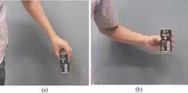
Fig. 1. Grasp of a can by a human
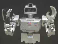
Fig. 2. Humanoid HRP3P with multi-fingered hand
(1) The humanoid hand can use human grasping styles and changes the grasping style depending on the position/orientation of the grasped object like a human. As shown in Fig.1, while a human grasps the side of the can with all the fingers, he/she grasps the top of it with just some of the fingers. Especially for the case of the robotic hands, it is often difficult to put all the fingers on the top of such a can.
(2) If our planner failed in finding the feasible grasping posture only by using the arm/hand kinematics, the planner tries to use the whole body kinematics. For the purpose of grasping an object firmly or reaching it, the robot try to change the shoulder position.
(3) We developed an easy and fast method of checking approximated force closure when a multi-fingered hand grasps an object. Different from previous methods, we consider approximating the friction cone by using an ellipsoid.
(4) Our grasp planner and grasp motion control are modularized as a plugin of Choreonoid, which is an integrated software that allows us to choreograph robot motions and simulate the robot motion dynamics.
(5) We confirmed the effectiveness of our proposed approach by experiment using the robot
HRP-3P (Fig. 2).
As for the works on grasp planning, there are a number of works on contact-level grasp synthesis such as Coelho & Grupen (2004); Niparnan & Sudsang (2004); Ponce et al. (1993). As


213 214 227 229
Fig. 3. Human grasping styles
for the grasp planning considering the hand/arm model, Cutkosky (1989) first proposed an expert system to select one of the grasp styles based on grasp quality measures. Pollard (2004) proposed a precise grasp planning algorithm by utilizing heavy computation. Morales et al. (2006) proposed a planning method applicable to the Barret hand. Morales et al. (2006) also proposed a method of planning a grasp by preparing the candidate grasping style corresponding to the grasped object. Prats et al. (2007) proposed a method for planning the hooking task of a door.
Recently, some researchers researched the fast grasp planning problem. ? proposed planning methods to determine contact positions of a four-fingered hand assuming a fingertip grasp. Miller et al. (2003) used a grasping simulator and proposed a method for determining candidates of a contact point set for grasp planning. Their method calculates 1 ∼ 44 candidates of grasp configuration between 11.4[s] and 478[s] depending on the complexity of the object’s shape. Their approach was extended to the learning approach (Pelossof et al. (2004)) and imperfect visual information (Ekvall & Kragic (2007)).
As for the grasp planning based on a random sampling approach, Niparnan & Sudsang (2004) and Borst et al. (2003) proposed methods to realize the force closure using the random sampling. Yashima et al. (2003) proposed a manipulation planning based on the random
sampling.
3. Grasp planning
Reference posture and rectangular convex
When a human grasps an object, a human selects one of the grasp styles according to the shape and the estimated mass of the object. Fig.3 shows some of the grasp styles shown in the book (Kapandji (1985)).
We assume that the shape of the object is given by a polygon model such as VRML. When the shape of the object is given, the grasp planner has to automatically select feasible grasp styles. For realizing this function, we assume the reference posture as shown in Fig.4. For each reference posture, we assigned the finger links contacting with the object. In this research, we constructed the reference grasping motion for three-fingered fingertip grasp, four-fingered fingertip grasp, and four-fingered enveloping grasp. We also constructed the reference posture for small, mid and large sized objects for each reference grasping motion.
We manually constructed these reference postures. For each reference posture, we assumed the grasping rectangular convex (GRC). The GRC is used for selecting the feasible grasping style for given grasped object. As shown in Fig. 5, we assumed three GRC. The GRCmax is the maximum size of the rectangular-shaped grasped
object without interfering the finger links. The GRCmin and the GRCdes are the assumed
minimum and desired sized grasped object.
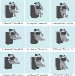
Fig. 4. Reference motion for several fingertip(FT) and envelope(EV) grasps
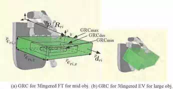
Fig. 5. Reference motion
By modifying the reference posture, the actual grasping posture is planned by using the method explained in the next section. For the i-th grasping style with the GRCmax which position/orientation is p pmax,i /p Rmax,i (i = 1, ··· , n), we assume the vector of the edge length p emax,i of the GRC. This vector is used for selecting the grasping style. Also, we assume the approach vector p dmax,i . This vector defines the approach direction to the object and is one of the outer unit normal vector of the GRC’s surface. Furthermore, we assume the maximum and the minimum mass, mmax,i and mmin,i of the object grasped by using the i-th grasping style.
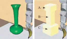
(a) Object model (vase)
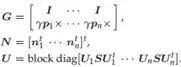
Fig. 6. Object and object convex polygon (OCP)
(b) OCP of deviced regions
Next, we focus on the object to be grasped. Given the shape of the object, our planner calculates the object convex polygon (OCP). The OCP is the minimum-sized convex polygons including the grasped object. In this paper, we consider the rectangular convex as the OCP. For complex shaped objects, we consider splitting the object into some regions and calculate the OCP. Fig.6 shows the OCP of the vase placed on the table. Our planner splits the object into three regions.
Once the polygon model of the grasped object is given, our planner has the set of points included in the surface of the object. By using the eigen vectors of the co-variance matrix of the point set, we can calculate the OCP. For the i-th OCP which position/orientation is poi /Roi
(i = 1, ··· , m), we assume the vector of edge length eoi. Miller et al. (2003); Pelossof et al. (2004) also used the convex model for the grasped object. In this research, in addition to the OCP, we use the GRC and determine the grasping style and the nominal grasping posture.
Nominal position/orientation of palm
Let us consider selecting one of the grasping styles and determining the nominal position/orientation of the palm. For such purpose, we introduce some heuristic rules in this subsection. We first focus on the geometrical relationship between the GRC and the OCP. Let sort(a) be the function replacing the elements of the vector a in a decreasing order. We impose the following conditions:
bmax,ij = sort(emax,i ) − sort(eoj ) > 0 (1)
bmin,ij = sort(eoj ) − sort(emin,i ) > 0 (2)
i = 1, ·· · , n, j = 1, ·· · , m
If bmax,ij > 0 and bmin,ij > 0 are satisfied, the OCP can be included inside the GRCmax. In this case, the hand may be able to grasp the object by using the i-th grasping style. Also, we use the following function to select the grasping style:
lij = ||sort(edes,i ) − sort(eoj )|| (3)
i = 1, ·· · , n, j = 1, ··· , m
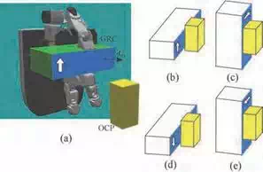
Fig. 7. Four possibilities for palm position/orientation
Let m be the mass of the object. We also impose the following conditions:
δmmax = mmax,i − m > 0 (4)
δmmin = m − mmin,i > 0 (5)
If there are multiple candidates of grasping styles, our planner selects one grasping style according to the nominal palm position/orientation. Due to this function, the robot can select the different grasping style for the same object if the position of the object is changed.
Once the grasping style is determined, our planner next determines the nominal position/orientation of the palm. Fig.7 shows the overview of the method. Let us focus on the surface of the GRCmax having the approach vector dri as its normal. Assuming that this surface is parallel to one of the surface of OCP and that the center of GRC coincides with the center of the OCP, there are four possibilities for the orientation of the GRC as shown in (b),(c),(d) and (e). For this example, the posture of the GRC shown in (b) and (d) is not feasible since the GRCmax does not include the OCP even if the GRC moves to the direction of the approach vector. On the other hand, for the position/orientation of the palm shown in (a) and (c), we try to solve the inverse kinematics of the arm. If the inverse kinematics problem has a solution, our planner considers it as a candidate of the nominal position/orientation of the palm. We iterate this calculation for all surfaces of the OCP without contacting another OCP. In case, we have multiple candidates of the nominal position/orientation of the palm, we have to select one. In this research, we select the nominal position/orientation of the palm which has the minimum norm of joint angles of the wrist.
Force closure condition
Conventional methods
When a multi-fingered hand grasps an object, an appropriate force/moment has to be generated onto the grasped object in order to balance any direction of the external force/moment. This condition is satisfied if the set of resultant force/moment applied by each finger includes the origin. This condition is known as the force closure. The set of resultant force/moment applied to the object can be obtained by calculating the sum of contact force applied by each finger where the contact force is limited inside fiction cone.
Let us consider the contact force fi (i = 1, ··· , m) applied at the i-th contact point position pi . The wrench wi generated by fi can be calculated as
wi =
fi
γpi × fi
. (6)
where γ is torque magnitude which is scaled with respect to the force magnitude. The space spanned by all contact forces is called the grasp wrench space (GWS). Ferrari & Canny (1992) proposed two methods of generating GWS. One method generates GWS (WL∞ ) by calculating the sum of all combination of contact forces. It is the Minkowski sum of the wrench applied by each finger. The other method generates convex hull of contact wrenches as GWS (WL1 ). The set of GWS, WL∞ and WL1 are expressed as,
| i=1 |
WL∞ = {⊕m
wi |wi ∈ Wi } (7)
m
WL1 = Convex Hul l ({∪i=1wi |wi ∈ Wi }) (8)
where ⊕ is Minkowski sum, Wi is a set of the effect wrench applied at i-th each contact point. When GWS contains the origin of wrench space, we say that the grasp is force closure. If a set
| 1 |
of vectors, wi ∈ Wi positively spans ℜ6 , then both WL∞ and WL will contain the origin. For
testing whether or not, GWS contains the origin, WL1 is useful because of its fast calculation.
However, for the purpose of dynamic motion planning of grasped object and more accurate grasp stability evaluation, WL∞ is needed. Since WL∞ space shows the range which can counter external wrench or inertial wrench in any direction.
For constructing WL∞ , the friction cone has been approximated by using a polyhedral convex cone. In this case, if we consider accurately approximating the friction cone by using a larger number of the faces, it results in the dramatic increase of the calculation cost. Let m and n be the number of finger and the number of face of the polyhedral cone, respectively. Its calculation cost is represented as O(nm ). Reduction of the calculation cost of WL∞ is important issue for grasp planning.
As for the research on force closure, Reuleaux (1976) discussed force closure used in classical mechanics. Ohwovoriole (1980) and Salisbury & Roth (1982) introduced it into the research field of robotics. Mishra et al. (1987), Nguyen (1988), and other researchers (Park & Starr (1992)-Ponce & Faverjon (1995)) investigated the construction of force closure grasp by a robotic hand. Kerr & Roth (1986), Nakamura et al. (1989), and Ferrari & Canny (1992) discussed the optimal grasp under force closure.
Linear matrix inequality (LMI) method (Han et al. (2000); Liu & Li (2004)) is a fast method of force closure testing. LMI method can find a solution which satisfying the friction constraint quickly. Some methods are derived from LMI method, such as ray tracing method (Liu (1993);
Zhen & Qian (2005)), and heuristics approach (Niparnan & Sudsang (2007)). They are fast method for testing force closure and find optimal solution.
Borst et al. (1999) proposed a method of incremental expansion of subspace of in the weakest direction of WL∞ . It is faster than conventional methods for grasp stablity evaluation of WL∞ .
Ellipsoidal approximation of friction cone
We have proposed a fast method of grasp stability calculation. Our method simply checks inequalities for force closure judgment and does not need to construct convex hull or to solve linear programming problem. If we approximate the friction cone by using a single ellipsoid, the force closure can be confirmed by checking only one inequality.
 Minkowski sum approximation ellipse
ellipses
Fig. 8. Minkowski sum of two ellipses and its approximation
By using the nominal position/orientation of the palm, now we determine the final grasping posture. The grasping posture is determined so as to satisfy several constraints imposed on the grasp system.
The grasped object has to resist the external wrench without breaking the contact. For this purpose, we formulate the wrench set generated at a point in the object. In our method, we consider approximating the friction cone constraint by using multiple ellipsoids.
Let us consider the contact force fi (i = 1, ··· , n) applied at the i-th contact point position pi . One of the ellipsoids approximating the friction cone can be expressed as
| i |
(fi − fmaxni )t Ui SU t (fi − fmax ni ) ≤ 1 (9)
where S = diag[μ fmax /√2 μ fmax /√2 α fmax ], μ is a friction coefficient, and Ui is a 3 × 3 matrix composed of the unit normal and tangent vectors. By using this equation for n contact points, the set of the wrench w generated by the object can be given by
f (p1 , ··· , pn ) =
(w − fmaxGN )t (GU −1Gt )−1 (w − fmax GN ) ≤ n
 (10)
(10)
Where
This method is useful since we can check the force closure condition very quickly just by calculating the left-hand side of eq.(10) (Fig. 8).
Searching final grasping posture
Failing to find feasible grasping posture using arm/hand kinematics alone, our planner attempts to search the one using full body kinematics. If the robot has joints which can move without losing humanoid body balance, then we add them to an arm joint list. By using the new joint list, inverse kinematics of the redundant joints is solved.
In the case of the robot can squat down, we add the virtual joint which moves shoulder height to the list. If a inverse kinematics of the joint list is solved, the waist height is acquired using the shoulder position. To obtain the final grasping posture, we use the random sampling technique. Let n be the number of fingers. We use 2 + n variables to search for the final grasping posture; ∆pp ∈ R3 ,
∆ps ∈ R3 and ∆ai ∈ R3 (i = 1, ··· , n).
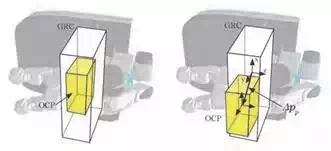
Fig. 9. Sample the position of OCP w.r.t. GRC
As shown in Fig.9, the three dimensional vector ∆pp expresses the position of the OCP w.r.t. its nominal position and is used to determine the position of the palm. On the other hand, ∆ps and ∆pi (i = 1, ··· , n) express the position of the shoulder and the i-th fingertip, respectively, w.r.t its nominal position. Here, as for ∆ps of this paper, we only change the vertical component of this vector if it is difficult to find the grasping posture when ∆ps = 0.
Planning algorithm
We assume that we have the polygon model of both the finger and the grasped object. To check the collision between the finger and the object, we used the software PQP (Proximity Query Package). By using PQP, even if two polygon models do not contact each other, we can calculate the distance between two models, the points on both models where the distance is the minimum, and the unit normal vector on the points of the model’s surface.
We first explain the method to find the posture of a finger contacting the object. First, for each grasping style, we defined the links of the fingers contacting the object. Then, for each defined link, we assign a joint of a finger compensating its position. We change the angle of
the assigned joint by a small amount and checked the collision between the link and the object. We iterate this calculation until the distance between the link and the object is smaller than a predefined value.
By using the pseudo code shown in Algorithm 1, we summarize the algorithm explained in this section. In this algorithm, after confirming that n − f (p1 , ··· , pn ) ≥ δ f is satisfied, we terminate the algorithm.
Grasping module
We implement our grasp planning module on a software platform Choreonoid (Fig. 10), which is an integrated software that allows us to choreograph robot motions via the interface and simulate the robot motion dynamics. We develop the grasping module has functions of a grasp planner, a motion trajectory planner, and a planning result viewer. We use also RT-middleware which are standardized by OpenRTM (2010). The grasping module can connect other RT-components such as image processing, sound recognition, and sensor network.
We describe user interfaces of the grasping module. There are 5 buttons for executing grasp planning.
SetRobot Assign a working robot to the selected item.
SetObject Assign an grasped object to the selected item.
Algorithm 1 Determination of Grasping Posture for n finger grasp
loop loop
Sample ∆pp and ∆ps .
if Arm IK is solvable then break
end loop
for i = 1 to n
for j = 1 to m
Sample ∆pi .
if Finger i IK is solvable then
if Found finger i posture contacting object then break
end if
end for
if Not found finger i posture then break
end for
if n − f (p1 , ··· , pn ) ≥ δ f then break end loop
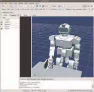
Fig. 10. Grasping module on choreonoid
SetEnv Assign obstructions to the selected items.
Start Start grasp planning.
Stop Abort grasp planning.
The result of grasp planning is showed on a graphics window.
Results
Simulation
To confirm the effectiveness of the proposed method, we show some numerical examples. As a model of the hand/arm system, we use the 7dof arm of the HRP-3P and a developed 4 fingered hand. This 4 fingered hand has the thumb with 5 joints and the index, middle and third fingers with 4 joints. The distal joint of each finger is not directly actuated and moves along with the next joint.
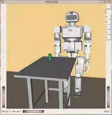
Fig. 11. Simulation environment
We prepared 9 reference motion as shown in Fig.4. The overview of numerical example is shown in Fig.11. We used a can with 0.15[kg] placed on the table as a grasped object. For this weight of the object, the grasp planner selects 3-fingered fingertip grasp or 4-fingered fingertip grasp. For each grasping style, we make only the distal link of finger contacting the object.
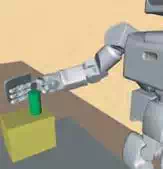
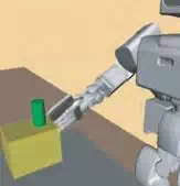
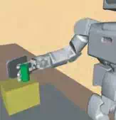
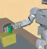
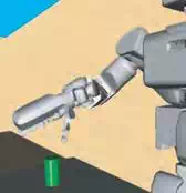
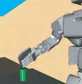
As shown in Fig.12, when grasping the can at a breast position, the humanoid robot grasps the can by using the four-fingered fingertip grasp. On the other hand, as shown in Fig.13, when grasping the can at waist height, the finger grasps the top of the can by using the three-fingered fingertip grasp. When grasping the top of the can, it is often difficult to grasp it by using the four-fingered fingertip grasp due to the size of the fingers.
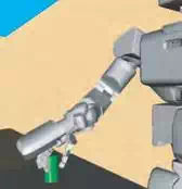
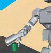
On the other hand, we set the weight of the object as 0.35[kg] for the case of Fig.14. In this case, the humanoid robot grasps the object by using the enveloping grasp with squatting down since it is difficult to grasp the object by simply standing on the ground. Then we performed experiment. As an grasped object, we used a 200[ml] can. We set mmax,i and mmin,i so that the hand grasps this can by using the enveloping grasp. In case of the enveloping grasp, we determined the finger posture (the 10th line of Algorithm 1) as follows; We first set that the distal (5th) link of the thumb and the 2nd and the 4th link of other fingers contact the object. Then, for the finger links contacting the object, we assigned a joint to each link supposed to make contact and adjusted the angles of this joint. If all the contacts are realized at the same time, 10th line of Algorithm 1 returns true. This grasp planning takes less than 1[s] by using Pentium M 2.0[GHz] PC and the calculation time of force closure is less than 1[ms].
Experiment
Fig. 15(a) shows the image taken by the camera attached at the head of HRP-3P humanoid robot. Three cameras are attached at the head. We used image processing software developed in VVV, AIST (Maruyama et al. (2009)). Given the geometrical model of the can, the position/orientation of it was calculated by using the segmentation based stereo method. Fig. 15(b) shows the result of extracting the segment. Although it takes less than one second
(a) (b)
(c) (d)
Fig. 12. Four-fingered fingertip grasp when grasping a can at breast height
to obtain the position/orientation of the can, we took the image for a few times to cope with the fault of the image processing.
The image processing was performed on the same PC with the motion planner. This PC was connected to the cameras by using IEEE 1394 cable. The image taken by the camera was processed by using this PC and the position/orientation data was transferred to the motion planner. After the motion planner plans the grasping motion, the joint angle data were transferred to the CPU boards controlling the motion of the robot. Here, we have two CPU boards installed in the chest of the robot where one is used to control the multi-fingered hand and the other is used to control the rest part of the robot. The wireless LAN is equipped with the robot. A directory of the motion planner PC was mounting on the CPU boards and the robot is controlled by using the joint angle data stored to this directory. As shown in Fig.16, HRP-3P successfully grasps objects.
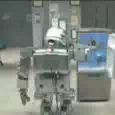
The robot takes out pet bottle from fridge as shown in Fig.17. At first, the robot opens the fridge door using settled motion. Vision sensor measures the object position and the planner cannot find a feasible posture only by using the arm/hand kinematics. The planner searches
a feasible posture by changing the shoulder height and finds it. The robot squats down and reaches the object and grasps it successfully.
(a) (b)
(c) (d)
Fig. 13. Three-fingered fingertip grasp when grasping a can at waist hight
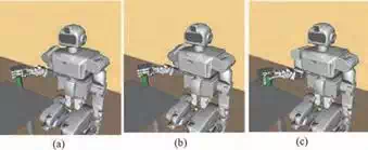
Fig. 14. Four-fingered enveloping grasp with squatting down
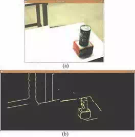
Fig. 15. Image taken by the stereo vision system


(a) (b)


(c) (d)
Fig. 16. Experimental result of grasping objects

(a) (b)

 (c) (d)
 (e) (f)
Fig. 17. Experimental result of taking out a pet bottle from a fridge
Conclusions and future works
In this chapter, we present algorithms of grasp planning for humanoid hand/robot system. By using the convex model for both hand and the object, the nominal palm position/orientation can be calculated easily. Also by using the ellipsoidal approximation of the friction cone, the grasp planning can be finished within a short period of time.
We improved the performance of the planner by considering the following things; First, depending on which part of the object to be grasped by the hand, our planner changes the grasping style. We numerically confirmed that, when grasping the side of the can, the robot grasps it by using the four-fingered fingertip grasp. On the other hand, when grasping the top of the can, the robot grasps it by using the three-fingered fingertip grasp. Also, if it is difficult to find the grasping posture only by using the arm/hand kinematics, the planner tries to use the whole body motion. We confirmed the effectiveness of our planner modularized as Choreonoid plugin by using experimental results.
Planner for the humanoid hand is necessary for future applications. Grasp planning would be improved on the dexterousness. The planner for multi-arm and handling objects has to be developed.


Comments are closed