In recent years, the scientific community has had an increased interest in exploring the asteroids of the solar system (JAXA/ISAS, 2003; JHU/APL, 1996; NASA/JPL, 2007). Technological advances have enabled mankind for the first time to take a closer look at these small solar system objects through sensors and instruments of robotic deep space probes. However, most of these space probe missions have focused on the reconnaissance of the asteroids’ surfaces and their compositional analysis from a distance. Little attention has been given to locomotion on their surfaces with a mobile robotic system, due to the challenging gravity conditions found in these small solar system bodies.
In small bodies like asteroids, the gravitational fields are substantially weaker than those of Earth or Mars, therefore the likelihood of a robot’s unintentional collision with the surface while attempting a movement is substantially higher. In one of the latest missions, the
Japanese Hayabusa spacecraft carried onboard a small robot named MINERVA (Yoshimitsu et al., 2001) to be deployed and used to explore the asteroid surface. The robot was designed with a single reaction wheel, located inside of it, to produce the necessary inertial reaction to move. But with this system the location of the robot when the motion is damped out is very challenging to predict or control. Subsequently, in order to maximize the scientific return from any given mission on an asteroid’s surface, future missions must have the ability to conduct stable mobility and accurate positioning on the rough terrain.
In the robotics field, limbed locomotion is broadly recognized as superior in its capability to traverse terrains with irregularities such as obstacles, cliffs and slants. Exotic types of wheeled rovers (Bares et al., 1999; Wilcox & Jones, 2000) can only drive over obstacles of heights that
are at best a fraction of the vehicle’s body length. Thus, some terrains are not accessible to wheeled vehicles. Conversely, legged or limbed locomotion has the possibility to provoke minimum reactions on the asteroid surface that could push the robot with sufficient force to reach escape velocity and drift into space. It also facilitates achievement of desired goal configurations that deal with new complex situations, ensuring that a robot’s behavior doesnot deviate from a stable condition.
In this chapter, the focus is on gravity-independent locomotion approaches, technologies and challenges of robotic mobility on asteroids. Recommendations and methods to perform
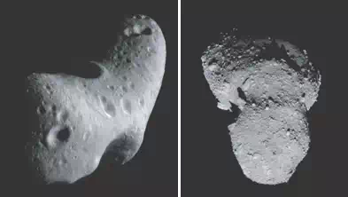 Fig. 1. Mosaic of Eros ©Applied Physics Lab/JHU and Asteroid 25143 Itokawa ©JAXA/ISAS
compliant motions during operations by a surface robot under microgravity conditions are presented. Taking into account the contact dynamics and the reaction force from its environment, a control scheme enables a limbed robot to move using the natural features of the environment and the friction of the surface for forward progress in any direction having contact only with the limbs’ end tips.
Asteroid exploration
Orbiting between 2.1 to 3.2 AU1 from the sun, primitive asteroids in the main asteroid belt represent key bodies to research on the early planetary system origin and evolution. Asteroids could provide clues about the birth and growth of our planetary system, but without any in-situ observation, we are not able to link measurements of asteroid material with a corresponding catalog of meteorite groups on Earth. The in-situ study of asteroids can lead to important scientific findings in the effort to map the main asteroid belt. Mapping the belt by spectral classes and knowledge about which region on Earth the meteorites have landed can provide key clues about the origin and evolution of our solar system, even including the geological history of our planet Earth (Fujiwara et al., 2006).
Asteroids’ physical characteristics provide a very hostile environment distinguished by the absence of (almost any) gravity. The effects of the microgravity environment can be approximated for convenience as those on order of 10−6 g (Scheeres, 2004) (where g is the acceleration due to gravity on Earth). In such an environment, objects basically do not fall, but remain orbiting unless they reach the low escape velocity of the asteroid on order of 20 cm/s (Scheeres, 2004), as in the case of the asteroid 25143 Itokawa (Fig. 1, right). To attain stable mobility on these bodies, it is critical to consider the interaction forces between a robot and the asteroid’s surface in such microgravity environments.
Relatively little attention from planetary scientists and planetary robotics engineers has been focused on surface mobility on asteroids. As a result, there exists some risk that premature conclusions about the feasibility of stable mobility on asteroid surfaces may be drawn without
| Gravity-Independent Locomotion: Dynamics and Position-Based Control of Robots on Asteroid Surfaces 3 |
thorough consideration of all possible alternatives. However, it is clear that in order to increase any scientific return from a mission operating on an asteroid, movement on the surface would require a closer look at stability control against the forces interacting between bodies in a microgravity environment.
The following section presents recent developments in robotics which may pose the most feasible solutions to asteroid surface exploration challenges.
Mobility in microgravity
Weak gravitational fields (micro-g to milli-g) characteristic of asteroids make it difficult to achieve normal forces usually required for stable surface locomotion. Various approaches to mobility in weak gravity domains of asteroids are discussed below.
Rolling and hopping locomotion
Although all rovers sent to other planetary surfaces have been wheeled vehicles, wheels are not an obvious solution for asteroid surface mobility. However, at least one study has suggested wheels to be viable in certain cases for rovers with mass less than one kilogram. Baumgartner et al (Baumgartner et al., 1998) reported that the analysis of whether adequate tractive forces can be achieved for rolling mobility depends on the wheel-terrain interaction model employed. Traction sufficient for a small rover to traverse at a rate of 1 cm/sec was shown to be feasible via dynamic simulations revealing traction losses at the beginning of traverses. The simulations separately considered Coulomb friction alone and a combined Coulomb friction and adhesive force model.
Behar conducted computer-based dynamic simulation studies of hopping and wheeled vehicles concluding that both types have limited use for asteroid mobility (Behar et al., 1997).
Hopping robots were deemed to be of limited utility due to complexity of both thruster control for accurate maneuvers and robot pose estimation. Wheeled robot utility was viewed as limited due to difficulty maintaining wheels on the surface when undesired surface reactions
led to long periods of ballistic floating before touching down. To mitigate difficulties of maintaining wheel contact with asteroid terrain, Behar proposed a colony of small robots that would traverse asteroid surfaces while connected to a common physical net that was anchored
to the asteroid. Robots connected to the anchored net would use wheeled locomotion to traverse along dedicated strands of the net. Another variation on rolling locomotion for asteroid mobility was proposed by Hokamoto and Ochi (Hokamoto & Ochi, 2001) based on a
vehicle with a dodecahedron shape and 12 individually actuated prismatic leg joints oriented radially around the body to provide intermittent walking and rolling.
When complexities associated with accurate 3-axis thruster-based maneuvers are avoided and replaced by simpler propulsion mechanisms, ballistic hopping is perhaps the simplest means of mobility for reaching discrete patches of asteroid terrain. The aforementioned MINERVA
vehicle was the only asteroid hopping rover fully developed for a space flight mission thus far. It was a 600 g vehicle designed for several asteroid days of autonomous operation involving ballistic hopping with variable hop speed and some control of hop direction depending on its attitude on the surface (Yoshimitsu et al., 2001). Other designs are in development or have been proposed as viable concepts. A 1.3 kg wheeled rover, at one time considered a payload for the Hayabusa mission on which MINERVA flew (Kawaguchi et al., 2003; Wilcox, 2000), was proposed with a novel mobility mechanism that also enables ballistic hopping. It further offered a capability to self-right in response to inevitable tumbling during landing from a hop or while traversing the surface at 1.5 mm/sec in low gravity (Tunstel, 1999).
Another hopping vehicle intended for asteroids is the Asteroid Surface Probe (Cottingham et al., 2009), an 8 kg battery-powered (100 hours) spherical body of 30 cm diameter that uses thrusters to hop. When stationary, the sphere opens up using 3 petals to expose a science instrument payload. The petals also provide the means to self-right the probe (Ebbets et al., 2007). Similar, in principle, is a 12 kg thruster-propelled ballistic free-flyer concept designed by the German Aerospace Center (DLR) as part of a European Space Agency study (Richter, 1998). Other hopping robots proposed for asteroid exploration include a pyramid-shaped, 533 g prototype with four single degree-of freedom (DOF) flippers at its base to enable hopping plus a lever arm for self-righting (Yoshida, 1999), and a spherical 1 kg robot with internal iron ball actuated by electro-magnets to induce hopping (Nakamura et al., 2000).
A recent study concluded that wheeled and hopping locomotion modes in low gravity are comparable in locomotion speed (Kubota et al., 2009). The study considered ideal conditions (e.g., flat terrain and no loss of contact between wheels and terrain). A similar conclusion regarding energy consumption was reached in a comparative study of wheeled and hopping rovers for Mars gravity (Schell et al., 2001).
Locomotion by crawling and climbing
Nature offers many existence proofs, in the form of animals and insects, for solutions capable of traversing rough terrain against forces of gravity. Limbed locomotion solutions are common among alternatives that could enable crawling or climbing to achieve viable mobility across asteroid surfaces.
Certain limbed mobility solutions for planetary rovers received limited consideration in the past for reasons of lower efficiency as compared to wheeled systems. Related arguments are less persuasive when dealing with the microgravity environment encountered on asteroids.
The same holds when considering mobility on planetary surfaces of extreme topography that are impossible to access using conventional wheeled systems. On asteroids, a means to cling to the surface (Yoshida et al., 2002) would offer a critical capability for controlled motion and
fine positioning. Limbs can also be beneficial as an active suspension that damps and prevents “bouncing” during traverse or upon landing after a hop. Crawling/climbing locomotion approaches without the use of limbs may also have merit for the asteroid domain. Such
“limbless” approaches are briefly discussed below followed by promising technologies and
concepts for clinging and gripping to surfaces.
Limbless crawling
A significant volume of engineering literature exists on research advances for snake-like or serpentine robots. A recent survey is provided in (Transeth et al., 2009). Robots have been developed to execute a variety of locomotion gaits inspired by snakes. Among them, the side-winding gait is perhaps best suited for effective locomotion under low surface friction conditions (Dalilsafaei, 2007) and especially effective for traversal of loose or slippery terrain (Hatton & Choset, 2010). The latest technologies for implementing side-winding gaits may provide viable solutions to local locomotion on asteroid surfaces. Relying largely on lateral friction forces, side-winding seems promising as a means to maintain surface contact but, in lieu of limbed mechanisms, may require additional means to adhere to the surface. Technologies such as dry adhesion are advancing for robotics applications in combination with mechanisms for climbing. Similar technologies can enhance the capability of a robotic side-winding mechanism. Discussed next are adhesive means of achieving secure surface
contact while crawling or climbing based on examples of technology proposed for space and planetary rovers.
Enabling adhesion technologies
Dry adhesive and electrostatic adhesion approaches that permit walking or climbing robotic systems to stick to natural surfaces hold promise for gravity-independent locomotion. An example is the Automated Walking Inspection and Maintenance Robot (AWIMR), a concept intended for operation on the exterior of crewed space vehicles or structures in space rather than on planet or asteroid surfaces (Wagner & Lane, 2007). The AWIMR engineers established the feasibility of walking on such surfaces with the aid of prototype sticky feet, inspired by gecko feet, using dry adhesive polydimethylsiloxane for adhesion. The robot’s sticky feet could walk on any clean, non-fragile surface (of the types found on space vehicle exteriors) and required a certain pull-off force. The AWIMR project also tested electrostatic means of sticking to surfaces, finding that greater shear forces were possible and that 2-3 kV was suitable for locomotion in this case (Wagner & Lane, 2007).
Bombardelli (Bombardelli et al., 2007) proposed artificial dry adhesives inspired by geckos and spiders for securing ballistically delivered microprobes to asteroid surfaces upon landing.
The preliminary study suggests that multilevel conformal adhesive structures may be key to the performance of the microprobe attachment system for unknown asteroid terrain.
The concept is motivated by the successful fabrication of several engineering prototypes of artificial reusable gecko adhesives. It is reported that the strongest such dry adhesive was recently fabricated using bundles of carbon nanotubes exhibiting four times the stickiness
of natural gecko foot hairs (Bombardelli et al., 2007; Ge et al., 2007). Some researchers have found carbon nanotubes to be intrinsically brittle but express confidence in their near-term robustness for climbing robots (Menon et al., 2007).
Among the desirable characteristics of synthetic, gecko-like dry adhesion for enabling asteroid traversal by rovers is its effectiveness on many surface types (as its functional basis is van der Waals forces), its effectiveness in the vacuum of space, the fact that no additional energy is required to maintain an established grip on a surface, and their potential for mimicking the self-cleaning or dust resistant property of natural gecko footpads (Menon et al., 2007; Silva & Tenreiro, 2008). The applicability of this technology for space and planetary robotic vehicles that would walk or climb on in-space structures and terrestrial surfaces is highlighted in (Menon et al., 2007). What could be considered early phases of suitable asteroid robot designs are briefly described in that work. We next discuss examples of technologies that
offer mechanical means for gripping with robot limbs or momentarily anchoring robot limbs to natural surfaces.
Limbs with gripping end-effectors
Limbed approaches employing gripping end-effectors as feet/hands can enable walking/climbing locomotion while maintaining contact with asteroid surfaces. The ability to grapple onto surfaces is key to gravity-independent locomotion allowing mobility in any orientation including steeply sloped natural terrain and upside down. Such “grapple-motion” capability enables natural surface traversal by clawing into regolith or forming grasping configurations against rough, hard surfaces of high friction.
During the past decade, prototypes of such limbed systems have been under development for planetary mobility and more recently focused on the problem of climbing steep terrain on Mars. A representative example of the state of the art for such applications is an 8 kg
four-limbed planetary rover, LEMUR IIb, for which several types of climbing end-effectors have been investigated (Kennedy et al., 2005). The locomotion functionality for the LEMUR-class of robots evolved (kinematically) from 6-limbed robots for walking on space structures in orbit to 4-limbed free-climbing on steep terrain. Technologies addressed during the development of free-climbing capabilities for LEMUR IIb (e.g., gripping end-effectors, force control, and stability-based motion planning) should be useful for gravity-independent locomotion on asteroids as well.
Recent work at Tohoku University spearheaded limbed locomotion solutions and prototypes that are more specific to asteroid surface mobility and explored the feasibility of statically stable grapple-motion in microgravity (Chacin & Yoshida, 2005). The work is motivated by a desire to achieve finer and more deterministic control of robot motion and position. The focus thus far has been a 6-legged rover with 4 DOF per leg and spiked/gripping end-effectors for grasping the asteroid surface. Motion control complexities are handled using a behavior-based control approach in addition to bio-inspired central pattern generators for rhythmic motion and sensor-driven reflexes. Dynamic simulation results showed that static locomotion is feasible when grasping forces on the surface can be achieved (Chacin & Yoshida, 2005). A 2.5 kg prototype of the Tohoku asteroid rover was built using a piercing spike at the tip of each limb to serve as momentary anchors in soft regolith or as contact points of a static grip on hard surfaces when used in combination (Chacin et al., 2006). Crawling gaits feasible for locomotion in microgravity environments using this system are analyzed in (Chacin & Yoshida, 2006) for stability (in the sense that they hold the rover to the asteroid surface).
The next section focuses on this robotic system as an example of an asteroid mobility solution and control approach. It considers issues related to the microgravity environment and its effect on dynamics of robotic systems on asteroids.
Asteroid robot – ASTRO
In a future asteroid exploration mission (Chacin & Yoshida, 2005; 2006; Yoshida et al., 2002), it is expected to have a smart design of a robotic system that would allow scientists to benefit from more accurate instrument positioning capability on the asteroid’s surface in microgravity. However, the engineering complexity of this task makes the design of an effective robot with stable locomotion difficult. A feasible robotic design for such a mission would be a small limbed robot deployed over the asteroid to crawl on its rough surface.
The asteroid robot ASTRO (Fig. 2) is a multi-limbed ambulatory locomotion system (Chacin et al., 2006) developed through the observation and imitation of clever solutions exhibited by biological systems. The robot is intended to use the natural features of the environment and the friction of the surface for omni-directional walking, having contact only at the limb end tips. This type of locomotion has the possibility to provoke minimum reactions on the asteroid surface thus avoiding excessive forces that could push the robot into space, or even the possibility to grasp the surface when some legs are controlled in a coordinated manner (Chacin & Yoshida, 2006).
During its development, the limbed robot concept was inspired from nature and other robots that have adopted the radially symmetric hexapod topology commonly used to obtain a platform complexity with a type of mechanism expected to perform robustly in unstructured environments, through the replication of walking gaits using six limbs like certain insects. A similar but much larger lunar rover concept is ATHLETE (Wilcox et al., 2007). However, while ASTRO and ATHLETE are kinematically similar, their distinguishable sizes and purposes enforce different sets of constraints to their designs. To eventually move on the Moon’s
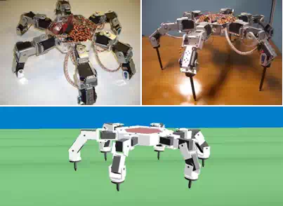 Fig. 2. Robot during early stages of development (top) and its simulated model (bottom).
surface, ATHLETE uses a combination of conventional rolling on wheels and quasi-static walking on wheels, and in ASTRO’s case, the use of six limbs was decided based on the needs of a mission to an asteroid, where the microgravity environment would impose on the robot the challenging task of moving with high accuracy and still performing science operations in a stable manner. The main purpose of this form of motion is to avoid getting ejected from the surface. Therefore, six limbs would be better than two or four, given the possibility of using at least three limbs to grasp the surface to maintain the robot’s attachment to the asteroid as a stable base while still using the remaining limbs for locomotion towards any direction or available for manipulation. Therefore, ASTRO is equipped with force/torque sensors on its end tips to provide feedback of the applied force to the surface.
ASTRO is expected to move on an asteroid surface with the capability of fine positioning over the surface to achieve science studies and mapping at several locations. As a result, the robot’s design has been developed in a modular basis for all of its components, facilitating any normal changes in the adaptation process to accomplish a robust design for the demanding activities imposed.
Finally, because the scientific objectives of asteroid exploration missions are so ambitious, extensive prioritization on the development had to be made. Given that no robot designed by the current effort is intended to be tested in space, the space-environment requirements
were given the lowest priority. This means that, the robot needs to be tested first in a 1g environment with as little information from its surroundings as possible.
General assumptions
Regular operations for limbed robots are characterized by multiple contacts between the limbs and the environment. In a microgravity environment, a planning algorithm can exploit this property by generating motions in contact, or more formally compliant motions (Borenstein,1995). During the execution of a compliant motion, the trajectory of the end tip is reflected according to the sensed forces derived from the contacts.
In this context, the problem of specifying a compliant motion command is similar to the problem of planning using pure position control to orient the end tip. The compliant motion control (Klein & Briggs, 1980) allows specification of the forces and velocities to be maintained in the motion frame until the meeting of a set of termination conditions is detected. Throughout the following analysis, to simplify the discussion, it is assumed that:
a1 ) The object is a rigid body in contact with a rigid link of the robot;
a2 ) Accurate models of the limbs and object are given;
a3 ) Interference between limbs is ignored;
a4 ) Each limb has only one frictional contact point at a fixed location;
a5 ) The z direction of the contact point is always inward of the surface normal;
a6 ) Contact points are known and the mass of each link of the robot is negligible;
a7 ) Dynamic and static frictional coefficients are not distinguished between each other;
a8 ) The motion is quasi-static2 to suppress any dynamic effect.
Assumption a4 allows us to consider only forces at the contact points. In this way, while executing a compliant command, the robot controller can interpret the sensed forces to automatically generate the corrective actions needed to comply with the task while preserving contact during motion.
Static friction occurs when the relative tangential velocity at a contact point is zero; otherwise, the friction is called dynamic friction. Assumptions a7 and a8 allow us to consider a “first-order” (or quasi-static) world where forces and velocities are related and also has static friction but no dynamic friction.
Dynamics model
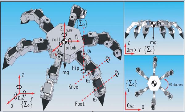
Surface mobile robots have the same structure in terms of dynamics equations as free flying or floating robots which do not have a fixed point but have interaction with the ground. The model of the robot developed in this research (Chacin & Yoshida, 2005) consists of a central body with a hexagonal shape and six identical limbs (Inoue et al., 2001; 2002) symmetrically distributed around it.
Each limb has three links and three actuated revolute joints. Two of these joints are located in the junction of the leg/limb with the central body. The third joint is located at the knee connecting the upper and lower link, which results in each limb having three DOF. Considering six legs and the additional six DOF for central body translation and rotation, the system has a total of 24 DOF.
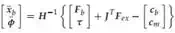
In this model, self-collision between limbs is ignored, meaning that links are allowed to cross each other, equal mass and length is assumed for all eighteen links, and that the joints are limited by internal mechanical stops. Any configuration of the robot can be defined by a set of parameters, the coordinates and orientation of the body, and the joint angles of each limb. The dynamic motion of the free-flying multi-body system with the presence of the external forces Fex is described as (Yoshida, 1997):
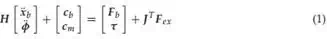
where,
H : inertia matrix of the robot
xb : position/orientation of the base
φ : articulated joint angles
cb , cm : velocity/gravity dependent non-linear terms Fb : forces/moments directly applied on the base τ : joint articulated torque
J T : Jacobian matrix
Fex : external forces/moments on the end points.
And the kinematic relationship around the end points is expressed as follows:
x˙ ex = J m φ˙ + J b x˙ b (2)
x¨ ex = J m φ¨ + J˙ m φ˙ + J b x¨ b + J˙ b x˙ b (3)
where J b and J m denote the Jacobian of the base (main) body and the Jacobian of a given manipulator (limb) respectively.
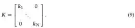
The magnitude of the forces is determined by the friction of the contact surface. Let us consider the i-th limb of the robot. Vectors pij ∈ R3×1 , f ij ∈ R3×1 and τij ∈ R3×1 denote the contact position, the contact force and the joint torque vectors, respectively; i and j express
| i |
the i-th limb and the j-th contact point. Let τ j be the torque due to the contact force f
relationship between the contact force and the joint torque is given by

ij. The
| i |
| ij |
where J T denotes the transpose of the Jacobian matrix that maps the contact force into the joint torque. Then, using the principle of superposition for the relationship between τ j and
f i , we have:
ki
| i |
τi = ∑ τ j
(5)
j=1
ki
| ij |
τi = ∑ J T f i
(6)
j=1
where, ki is the number of contact points of the i-th limb. Since it is assumed that a limb can only have one contact point, Equation 6 can be rewritten in the following form.
v
| m |
 K
K
Fcontact
Fig. 3. Contact model.
Limb compliance and stiffness
Given an applied force on the end tip, any kinematic chain (on any given limb) experiences a deformation. This relation between the applied force and the corresponding deformation is defined as the “stiffness” of the kinematic chain. This stiffness can be related to two possibilities: the mechanical elasticity of the system and/or the dynamic behavior of the control system.
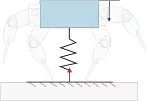
In general, for each joint there is a deflexion component defined by:
τ = K∆φ (8)
where
The relation between the force f i and the corresponding spatial deformation ∆ p is determined from the following relationship:
Solving Equation 8 for ∆φ,
And substituting in Equation 10,
∆ p = J ∆φ. (10)
∆φ = K−1 τ. (11)
∆ p = JK−1 τ. (12)

Finally, from Equation 7 and Equation 12,
∆ p = JK−1 J T f i . (13) From this point the compliance matrix can be defined as:
C = JK−1 J T . (14)
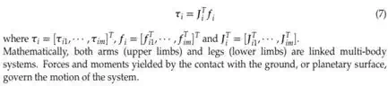
The impact phase can be divided into two stages: compression and restitution. During the compression stage, the elastic energy is absorbed by the deformation of the contact surfaces of the impacting bodies. In the restitution stage the elastic energy stored in the compression stage is released back to the bodies making the relative velocity greater than zero.
The robot can be modeled as a mass-spring system (Fig. 3) with a purely elastic contact at its end tips (Chacin & Yoshida, 2008). As a result, the following relation between the mass, the velocity and the force should hold:
Isolating the reaction force, we have:2mv = F ∆t. (15)
Now, considering the time of contact as a function of the mass of the system m and the stiffness coefficient of the limbs K, we have:
∆t = π m . (17)
K
Finally, from Equation 16 and Equation 17,
2 √
Fcontact = π
mK v (18)
with
N
F contact = ∑ f i (19)
i=1
where N is the number of limbs in contact at landing.
Contact dynamics
In commonly used contact models (Brach, 1991; Keller, 1986), the relationship of momentum exchange and force-time product assumes infinitesimal impact. However, the infinitesimal impact between two single rigid bodies is a much idealized case. When modeling the ground (natural terrain), it is usually observed that as the stiffness coefficient is lowered, greater penetration in the ground occurs. The lower the damping constants, the longer the vibrations occur. However, a very high increment in stiffness or in damping constants in the limbs’ model produces instabilities in simulations due to numerical issues that can be avoided by using a rigid limb, thus reducing the model order. The following discussion looks at how to determine the contact force F ex (Der Stappen et al., 1999).
Where there is friction at a contact point, the friction force at a point acts tangential to the contact surface. We will denote the magnitude of the friction force at the i-th contact as f i , an magnitude of the normal force as f n . To specify the tangential acceleration and friction force completely in a three-dimensional system, we would also need to specify the direction of the acceleration and friction force in the tangent plane (Gilardi & Shraf, 2002; Yoshida, 1999). Since the authors assume a model with a purely elastic deformation in the normal (z) direction of the contact point, and Coulomb friction in the tangential directions, we have the following general expressions from Fig. 4:
f ci−tg = f ci cosθ (20)
f ci−normal = f ci sinθ (21)
where θ is the angle of the surface normal.
z
v
μ θ θ
fci −tg
fci −normal
fci −tg
f
fci
fci −normal
 o
o
ci x
Fig. 4. Decomposition of the contact forces.
Next, the coefficient of friction can be denoted as:
| ci |
| > |
f f
μ =
| ci |
f ci−normal f
ci cosθ
sinθ (22)
μ > f ci tanθ. Considering Fcontact = f ci on the last expression, and using Equation 16 we have,
| μ > 2mv |
∆t tanθ. (24)
And substituting Equation 17,
tanθμ π m > v. (25)
2m K
Equation 25 shows that the considered contact stability will strictly depend on the approach velocity of the robot.
Quasi-static stability is a more general stability criterion than that used in the previous discussion. Under this condition, inertia forces are included but limb dynamics are not separately considered; the masses of the limbs are considered with that of the body. In the previous argument, quasi-static stability is partly assumed, provided all the normal components of the contact points’ f forces are positive. Since the contact point cannot support a negative normal force (as shown in Fig. 4), the appearance of a negative force indicates that the given limb will lift and, since it cannot provide the required movement about the center of mass, the robot will jump in a microgravity environment like MINERVA (Yoshimitsu et al.,
2001).
Motion control
If a robot is to successfully achieve walking with static stability, the control system must ensure that the behavior of the robot does not deviate from the following stable condition.
m
∑ f i + mo g = 0 (26)
i=1
m
∑ pi × f i = 0 (27)
i=1
To remain balanced, the robot must be able to apply forces with its end tips on the terrain that compensate for gravity without slipping. A necessary condition is that the robot’s center of mass lies above the support polygon. But on an irregular surface, the support polygon does not always correspond to the base of the contact points. To compute the support polygon the contact interface (all contact points) is modeled as shown in (Chacin, 2007), with
f n ≥ 0 (28)
f t ≤ μ f n . (29)
The support polygon is the projection of these polyhedrons onto the global coordinate system. The body attitude also needs to be controlled in order for the robot to maintain static balance. Assuming that the robot is well balanced in the lateral plane, the body attitude at any given moment is an important determinant of the acceleration experienced by the center of mass (COM) in the sagittal plane. If the desired value of the acceleration output is known at all times throughout the gait cycle, then a corrective action can be generated which will maintain the robot in a stable state. If the body attitude needs to be increased or decreased depending upon the error signal, and assuming that we can determine the desired acceleration in the sagittal plane for all times throughout the gait cycle, we can implement a continuous control system.
Zero moment point and momentum of the system
In the walking robotics community, Zero Moment Point (ZMP), which was first introduced by (Vukobratovic et al., 1970), is a key concept to discuss the tip-over stability and gait control of a robot. Fig. 5 is a schematic drawing to explain ZMP. Point O is the center of gravity (COG) of the entire robot. Let vector r be a position vector from an arbitrary point on the ground P to the point O, and vector li be a position vector from the point P to each ground contact point of the limbs. For this model, the following dynamic equilibria hold true
P˙ p = ∑ f exi + Mg (30)
L˙ p = n p + r × P˙ p + ∑(li × f exi ) (31) where P p and L p are linear and angular momentum around point P, and M is the total mass of the robot. The ZMP is a position P at which the component of moment np around the
horizontal axes, npx and n py , becomes zero. The robot is stable, otherwise if the ZMP stays inside a polygon formed by ground contact points of the limbs. Otherwise the robot starts tipping over.
Gait generation and motion control algorithms for walking robots have been developed based on this concept. In addition, an advanced planning and control algorithm with a special attention to the kinetic momentum has been proposed recently (Kajita et al., 2003).
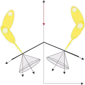
 ω v o
ω v o
Fex
g r
P np
Fig. 5. A schematic force/moment model for an articulated surface robot
For a surface limbed robot, the gravity forces exerted on it can be neglected; the non-linear term in Equation 1 then becomes cb = H˙ b x˙ b + H˙ bm φ˙ b . Integrating its upper set with respect to time, we obtain the total momentum of the system as:
| b |
L = J T F ex dt = H b x˙ b + H bm φ˙ . (32)
Going back to Equation 2, and eliminating φ˙ , we can obtain the following equation:
| s |
L = ( H b − H m J −1 )x˙ b
| s |
+ H m J −1 x˙ ex . (33)
In this way, if the system does depart from static stability, then the control system can identify this condition and bring the robot back to the statically stable condition.
Generalized control algorithm
Since walking is a continuous and cyclic process, we can consider two main types of control systems, a closed-loop control system and an event driven control system (Fig. 6). A general closed-loop control system for controlling the continuous process of the walking gait can be considered. However, since the positioning of the end tip itself can be modeled as a discrete process, we use an event driven control system to identify the existence of such states and modify the closed-loop control depending upon the current state of the system.
Given a motion command (a vector X ), the motion planning and control algorithm to move in the commanded direction and magnitude is carried out in the following way:
1 Use the gait planner presented in (Chacin & Yoshida, 2006) to plan the complete set of limb motions to move in the desired direction.
2 At time t, compute link positions and velocities, recursively from link 0 to n.
3 Set accelerations x¨ b and φ¨ to zero, and external forces F b and Fex to zero, then compute the inertial forces recursively from link n to 0. The resultant forces on the coordinates xb and φ are equal to the non-linear forces cb and cm , respectively.
4 Plan the end point trajectory of each limb xexi using the kinematics in Subsec. 4.6, so that ZMP satisfies the stability condition. Then obtain the end point velocity x˙ ex along the trajectory.
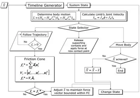
Fig. 6. Gait planner detail
5 Considering the friction cone estimation (Chacin, 2007) and the contact stability conditions shown by Equation 25, determine the robot base motion x˙ b by
6 Calculate the joint velocity of the limbs φ˙
by Equation 2, using x˙ b and
x˙ ex while
considering Equation 29; change the state of the control system. If necessary, adjust x
to maintain the force vectors bounded within the friction cones.
7 Adopt the new contact configuration to release the support contacts and apply a permissible contact force at the new contact points. Dynamic exploration can be applied to reduce the surface position/orientation uncertainties. Change the state of the control system.
8 Control the joints along with the solution from 6 to move the body. Verify if the goal
position X has been reached; if it has not, then repeat.
One difference of this algorithm with respect to conventional ones is the consideration of momentum of the robot in 3 . Without this step, the obtained joint motion may have errors from the originally planned end point trajectory, thus may not satisfy the stability condition. Conventionally, a feedback control may be employed to correct these errors. But using Equation 33 in 3 , the error can be compensated in advance.
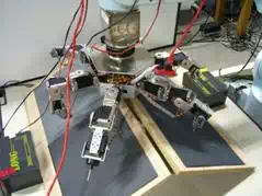
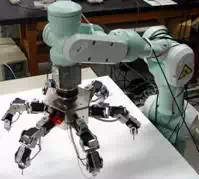
Fig. 7. The experimental setup: robot mounted on a PA10 manipulator (left) and over an uneven surface (right).
Emulating microgravity
To simulate the real dynamic conditions of a robot on an asteroid, the authors used a robust control system that could counterbalance Earth’s gravity and leave the robot in an emulated state of microgravity. For this reason, ASTRO was mounted on the tip of a Mitsubishi PA10 manipulator arm (Fig. 7) controlled by a dynamics based model simulation equipped with an ATI Industrial Automation Gamma SI-32-2.5 Force/Torque sensor (ATI, 2005). This sensor allows the appropriate control of the manipulator arm to emulate the microgravity condition that asteroid 25143 Itokawa would impose on the robot by means of calculating its position, force, acceleration and velocity with high accuracy using real-time impedance and dynamic compliance control.
Experiments were performed to observe and analyze the robot’s behavior under microgravity conditions, as it would approach the surface of an asteroid and perform motions on it. Gravity emulation is achieved through impedance control, also known as virtual compliance control,
as shown in (Hirabayashi et al., 2000). The control algorithm is based upon the basic equation of motion shown in Equation 34.
| − − |
[m] dv = q [K]∆x [C]v (34)
dt
where q is the external force and torque applied to the manipulator ’s end tip, ∆x is the displacement of the end tip relative to the reference and v is its velocity. [m] ∈ R6 is the virtual mass, [K] ∈ R6 is the virtual spring constant and [C] ∈ R6 is the damping constant. Equation 34 can be transformed into:
v = 1
[m]
(q − [K]∆x − [C]v)dt (35)
which can be represented as the following finite differential equation:
∆t ∆t
vn = [m] (qn−1 − [K]∆xn−1 )+ ([ I] − [m] [C])vn−1 (36)
where ∆t is the time step and [ I ] is the identity matrix. Equation 36 describes the velocity at the sampling time based upon values from the previous time step. Based on this equation,
80
60
![]() 40
40
20

0 2 4
6 8
time [s]
10 12
Fig. 8. Composite velocity profile of the manipulator ’s end tip.
and knowing the forces and torques as well as the displacement, the arm can be controlled in real-time using Equation 36 and Equation 1 to simulate the attached robot and to compensate the input of the F/T sensor on its tip. In short, the control policy uses the relationship between force and velocity to find the position and then calculate a velocity command as inputs to the system. The behavior of the system can be altered by changing the impedance constants [m], [K] and [C] as defined in Subsec. 4.3 and Subsec. 4.4 or can be fine tuned in order to exhibit the desired properties.
Preliminary tests
To evaluate the performance of the manipulator ’s control strategy, several tests were designed to examine how the impedance constants [m], [K] and [C] influence the behavior of the system. For simplicity, only four typical cases are described while keeping [m] constant to damp out small mechanical vibrations on the system.
During the first case, the parameters were selected under the following constraint K ≫ C. A force is applied on the manipulator ’s end tip, which is displaced before it starts swinging back and forth. A small reduction in the position is observed with time since the damping is not
zero.
In the second case the condition changes to K > C. As in the first experiment, the end tip starts to swing back and forth when a force is applied, but since the damping constant [C] has been increased, this swing motion dies out much faster as the end tip is back to its initial position without any further movement.
For the third case, the condition is switched to K C. When a force is applied, the velocity increases but it is quickly reduced back to zero. The position also exhibits a rather small change where it remains when the velocity is damped out.
In the fourth case, the spring and damping constants are selected to satisfy K < C, but both parameters are chosen similar to what they are expected to be in a microgravity environment, where both [K] and [C] tend to zero3. It was observed that the manipulator ’s end tip velocity changes rapidly, and then it slowly decreases due to the small damping coefficient.
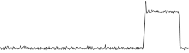
Several tests designed to verify the energy absorption and the velocity profile of the manipulator arm were performed. Typical experimental results are shown in Fig. 8.
The manipulator ’s end tip velocity changes after impacting the surface but remains within 10%-15% of its approaching phase yielding reasonable results that are in accordance with what is expected in microgravity conditions. At this point, if the virtual mass value is to be
changed in any of the experiments, the behavior of the system would not change, but the force
2.0
![]() 1.5
1.5
1.0
0.5
0.0
0
1 2 3 4 5
time [s]
Fig. 9. Force profile during motion without control feedback.
required in order to get the same velocity and position displacement would have increased accordingly. Similar experiments have been carried out for rotational and multi-translational movements, but their description has been omitted to show these results as the basic principle behind the selection of proper parameter values.
After achieving a satisfactory response from the control system, ASTRO was attached to the end tip of the manipulator and was suspended above a table that serves as analog to the
asteroid surface.
Experimental results
To demonstrate the concept and to verify the control strategy, further experiments were performed under the dynamic conditions shown in the previous section, and for comparison, motion was attempted first without control or feedback and then using the control algorithm described in Subsec. 4.7. In the first motion experiment, the robot was commanded to go forward over a rugged surface4 with a known inclination angle, while keeping a stable and statically balanced position. The problem of control is simplified by giving the control system the geometry5 of the environment and the gait is calculated off-line.
Although the robot successfully took three contact points and executed one gait motion, the selected contact points were not ideal, and the robot exhibited pronounced oscillating swaying motions in the lateral plane causing slip. This can be seen in the force data (Fig. 9). It was observed that after the gait missed the contact points the stability of the system was severely undermined. This instability at the end tips could cause the unpredictable behavior of the robot due to the escalating effect of the accumulative error. This is somewhat indicative of the dynamic behavior of uncontrolled hopping robots in similar microgravity environments.
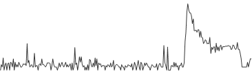
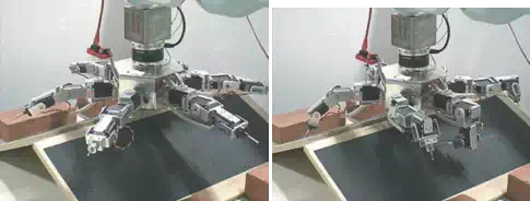
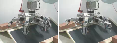
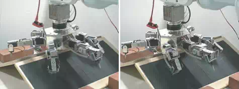
Due to the contact instability of the previous attempt, the ability of the robot to use the information from the friction forces (friction cones) while walking on the surface was further examined (Fig. 11). The overall stability of the walking gait depends upon the timing of
the motion from the gait planner. If the timing is incorrect, it will affect the stability of the robot during the walking gait. It is, therefore, desirable to study the relationship between the stability of the robot and the motion conditions. The stability of the robot can be examined by
enabling the robot to walk continuously on the surface using the control strategy presented in Subsec. 4.7. This has the desired effect of reducing end tip momenta which are created when the robot translates or rotates an end tip, which can increase the instability of the contact.
7
6
5
4
![]() 3
3
2
1
0 1 2 3 4
time [s]
Fig. 10. Force profile during motion with control feedback.
The results of this experiment are shown in Fig. 10. It can be noted that the force values are higher, but more importantly the robot is resting balanced on the limbs in contact with the surface. With the feedback from the force sensors, the control system was able to determine an appropriate corrective measure for the robot to take in order to maintain the stability of the contact while keeping its attitude (expressed in roll-pitch-yaw angles) mostly unchanged during motion. For the case where the robot is under a known environment and the desired forces to be exerted on the surface are known in advance, any deviation from this state should cause an appropriate corrective action to be taken.
Challenges
A rich set of challenges are encountered during development and evaluation of prospective solutions for gravity-independent locomotion on asteroids. The experiments reported here are indicative of a few, but several additional key challenges deserve early attention by researchers. One of them is the mechanics of controlled ballistic hopping on rotating asteroids and in non-uniform gravity fields due to their irregularly shaped bodies. Bellerose et al (Bellerose et al., 2008; Bellerose & Scheeres, 2008) modeled the dynamics of hopping vehicles to enable hops covering designated distances by computing and controlling initial hop velocity. The model accounts for distance covered by residual bounces as the vehicle comes to rest (considering surface friction coefficient and restitution). A particularly challenging aspect to consider is that some asteroid shapes may have surface locations where a vehicle could stay in equilibrium, thus affecting vehicle dynamics on the surface (Bellerose et al., 2008; Bellerose & Scheeres, 2008).
Conceivably, a hopping rover could be perturbed away from predicted ballistic trajectories by such equilibria. This can affect exploration objectives by constraining the total area that a rover can safely or reliably traverse to on an asteroid surface when stable and unstable equilibrium locations happen to coincide with surface regions of scientific interest. Purely hopping vehicles that operate primarily at the mercy of small body physics can have limited accessibility of such surface regions. Bellerose’s model also provides insight into the effects of non-uniform gravity fields and how centripetal and Coriolis forces due to asteroid rotation may assist or hinder hop performance (Bellerose & Scheeres, 2008). Another key challenge is achieving the ability to land after hopping in such a way as to avoid rebound. Control and robotics techniques can be used to address this challenge. One robot concept employs a spring and linear actuators with horizontal velocity control to achieve this (Shimoda et al., 2003), while other research is experimenting with active grappling of the surface upon landing (Chacin, 2007; Chacin & Yoshida, 2008; 2009). The related challenge, central to gravity-independent locomotion, is maintaining grip or temporary anchoring while controlling force for closure and compliance. The work presented herein and in (Chacin
 (a) (b)
 (c) (d)
 (e) (f)
Fig. 11. Movement over inclined frictional surface with friction feedback gait control.
& Yoshida, 2009) examines the motion/force control and dynamic modeling germane to the problem of stable crawling and force closure needed to maintain contact/grip with an asteroid surface under microgravity conditions. Experiments with ASTRO reveal the utility of force feedback for maintaining contact during execution of compliant motion. Kennedy et al (Kennedy et al., 2005) address active force control to achieve anchoring associated with stable free-climbing motion control. Tactile sensing and related motion planning algorithms (Bretl et al., 2003) have been implemented on the LEMUR IIb robot.
The low gravity environment and its effect on surface vehicles present a key challenge for rover localization whether hopping, crawling, or climbing. Determining, updating and maintaining knowledge of rover position and orientation on an asteroid surface can be
important for recording spatial context for surface science measurements and for certain mission concepts of operation. Localization approaches for hopping robots have been proposed with some reliance on range measurements to an orbiting or station-keeping mother
spacecraft (Yoshimitsu et al., 2001) and via use of more general approaches such as particle filters (Martinez, 2004), Kalman Filters with landmark geo-referencing (Fiorini et al., 2005), and optical flow as well as visual odometry without continuous terrain feature tracking while
tumbling (So et al., 2008; 2009). During local navigation across the terrain, existing localization approaches for rolling or walking robots may apply. These may be based on use of extended Kalman Filters on fused celestial sensor data and optical-flow measurements (Baumgartner et
al., 1998).
Finally, a key challenge is the testing and verification of gravity-independent locomotion systems to ensure confidence in their technology readiness for asteroid missions. This is always a challenge for space systems and particularly those intended for operation in
microgravity domains. The testbed described in the previous section and its means of emulating reduced gravity are representative solutions for addressing the challenge using relatively affordable technology. Other testbed approaches to emulating reduced gravity in
the laboratory include the use of overhead gantry systems with frictionless air-bearing pulleys from which to suspend prototype rovers, and the use of prototype rovers on flat air-tables or mounted on a mobile base with integrated air bearings. Beyond the fundamental feasibility of
controlled surface mobility in low gravity fields of asteroids, additional challenges of high relevance and importance remain to be addressed by advanced research and technology development.
Summary and conclusions
In this chapter, various approaches to gravity-independent locomotion on weak gravity surfaces of asteroids are discussed along with related technologies. Challenges are also described that affect planning and control of surface exploration robots that use hopping and rolling mechanisms and/or articulated limbs for the ground contact.
Given the focus on gravity-independent locomotion approaches, technologies, and challenges of robotic mobility on asteroids, an in-depth representative example of an asteroid mobility solution and control approach is provided. The control approach considers reaction and friction forces with the asteroid surface and is demonstrated using a prototype robot (ASTRO) and laboratory testbed that emulates microgravity. This example considered issues that most solutions must address related to the microgravity environment and its effect on dynamics of robotic systems on asteroids.
The research presents a planning and control structure for the locomotion of a multi-limbed robot under microgravity conditions. The algorithm can be considered as constructive proof
that there exists a solution that satisfies the force conditions for any system with friction. It works by reacting to the current locations of contact points and estimating the force-closure condition for stable motion. Such a mechanism is central in the control structure.
The control methods proposed in this research are useful to improve the operational performance and efficiency for robots capable of position-based controlled motion on an asteroid. They demonstrated that proper knowledge of the force cone interaction with the surface plays a significant role in the development of proper control procedures that can allow next-generation surface robots to gain proper mobility in a microgravity environment.