Interpretation of human gestures by a computer is used for human-machine interaction in the area of computer vision [3][28]. The main purpose of gesture recognition research is to identify a particular human gesture and convey information to the user pertaining to individual gesture. From the corpus of gestures, specific gesture of interest can be identified[30][36], and on the basis of that, specific command for execution of action can be given to robotic system[31]. Overall aim is to make the computer understand human body language [14], thereby bridging the gap between machine and human. Hand gesture recognition can be used to enhance human–computer interaction without depending on traditional input devices such as keyboard and mouse.
Hand gestures are extensively used for telerobotic control applications [20]. Robotic systems can be controlled naturally and intuitively with such telerobotic communication [38] [41]. A prominent benefit of such a system is that it presents a natural way to send geometrical information to the robot such as: left, right, etc. Robotic hand can be controlled remotely by hand gestures. Research is being carried out in this area for a long time. Several approaches have been developed for sensing hand movements and controlling robotic hand [9][13][22]. Glove based technique is a well-known means of recognizing hand gestures. It utilizes sensor attached mechanical glove devices that directly measure hand and/or arm joint angles and spatial position. Although glove-based gestural interfaces give more precision, it limits freedom as it requires users to wear cumbersome patch of devices. Jae-Ho Shin et al [14] used entropy analysis to extract hand region in complex background for hand gesture recognition system. Robot controlling is done by fusion of hand positioning and arm gestures [2][32] using data gloves. Although it gives more precision, it limits freedom due to necessity of wearing gloves. For capturing hand gestures correctly, proper light and camera angles are required. A technique to manage light source and view angles, in an efficient way for capturing hand gestures, is given in [26]. Reviews have been written on the subsets of hand postures and gesture recognition in [6]and [18]. The problem of visual hand recognition and tracking is quite challenging. Many early approaches used position markers or colored bands to make the problem of hand recognition easier, but due to their inconvenience, they cannot be considered as a natural interface for the robot control [24]. A 3D Matlab Kinematic model of a PUMA [1][4][16] robot, is used for executing actions by hand gesture[39]. It can be extended to any robotic system with a number of specific commands suitable to that system [17].
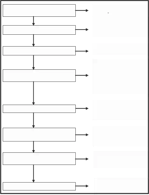
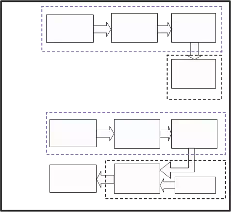
In this chapter, we have proposed a fast as well as automatic hand gesture detection and recognition system. Once a hand gesture is recognised, an appropriate command is sent to a robot. Once robot recieves a command, it does a pre-defined work and keeps doing until a new command arrives. A flowchart for overall controlling of a robot is given in figure 1.
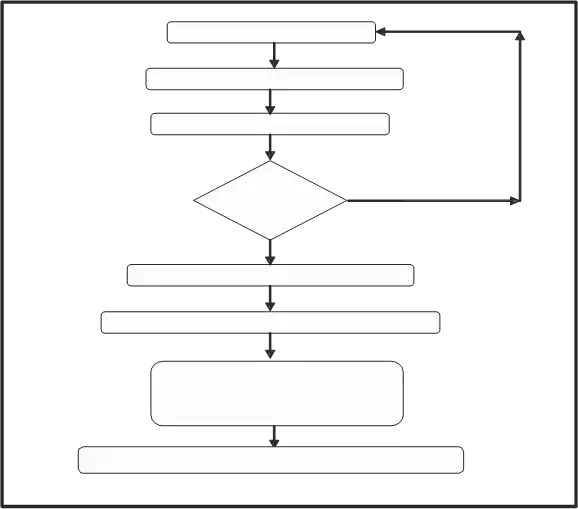
Video Capture of hand movement
Normalization (Improving image brightness)
Smoothing (Removing Noise)
No
contains object of interest?
Frame contain object of
Yes
Frame
Crop unused extra part (i.e. removal of wrist, arm etc)
Compare and match the gesture using Principal Component Analysis
(PCA)
Identification of Gesture and Extaction of instruction set corresponding to the matched gesture
Passing the instructions to robot for execution of corresponding
Commands.
Fig. 1. Flow diagram for robot control using hand gestures
Methodology
The proposed methodology involves acquisition of live video from a camera for gesture identification. It acquire frames from live video stream in some given time interval[15]. In this case frame capture rate for gesture search is 3 frames per second. The overall proposed
technique to acquire hand gestures and to control robotic system using hand gestures is divided into four subparts:
• Image acquisition to get hand gestures.
• Extracting hand gesture area from captured frame.
• Determining gesture by pattern matching using PCA algorithm.
• Generation of instructions corresponding to matched gesture, for specified robotic action.
Image acquisition to get hand gestures
First step is to capture the image from video stream. It is assumed that while capturing video, black background with proper light soure is used. To minimize number of light sources, arrangement of the light sources and camera is made as shown in figure 2.
Light Source
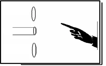 Camera
Light Source
Fig. 2. Arrangement of light sources for image aquisition
From video stream one frame is captured every 1/3 of a second. Our aim is to identify the frame that contains hand gesture shown by human. For this we are searching the frame in which there is no or least movement. Required frame is identified by comparing three continuously captured frames. Motion parameter is determined for each frame by counting total pixels of mismatch. If motion parameter is less than the specified threshold value, it is considered as a frame having least movement of object i.e. the hand of the person.
Analysis of frames to find the frame of interest is carried out by converting the captured
frame into a binary frame[23]. Since binary images have values of one or zero., differences of white pixels between newly captured frame and two previously captured frames are determined and they are added together to find motion parameter. XOR function is used to find the differences in white pixels [5][15].
If frame1, frame2, and, frame3 are three matrices containing three frames captured in three continuous time slots respectively then:
fr1 = frame1 XOR frame3 (1)
fr2 = frame2 XOR frame 3 (2)
Here r and c are the number of rows and columns in an image frame. Threshold value is set as 0.01. i.e. if total pixels of mismatch are less than 1% of total pixels in a frame, then it is considered as frame of interest. Required frame is forwarded for further processing and this module again starts searching for next frame of interest.
Extracting hand gesture area from frame of interest
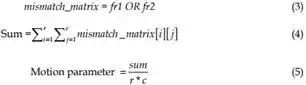
It may happen that the frame, as shown in fig.3, with a gesture contains extra part along with required part of hand i.e. background objects, blank spaces etc. For better results in pattern matching, unused part must be removed. Therefore hand gesture is cropped out from the obtained frame. Cropping of hand gesture from the obtained frame contains three steps:
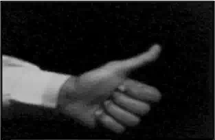
Fig. 3. Grayscale image
First step is to convert selected frame into HSV color space. As shown in fig.4, a HSV based skin filter was applied on the RGB format image to reduce lighting effects [8][1]. The thresholds for skin filter used in the experiment were as below:
0.05 < H < 0.17
| → |
0.1 < S < 0.3
(6)
0.09 < V < 0.15
The resultant image was segmented to get a binary image of hand[37]. Binary images are bi- level images where each pixel is stored as a single bit (0 or 1). Smoothening was needed, as the output image had some jagged edges as clearly visible in figure 4(c). There can be some noise in the filtered images due to false detected skin pixels or some skin color objects (like wood) in background, it can generate few unwanted spots in the output image as shown in figure 4(e).
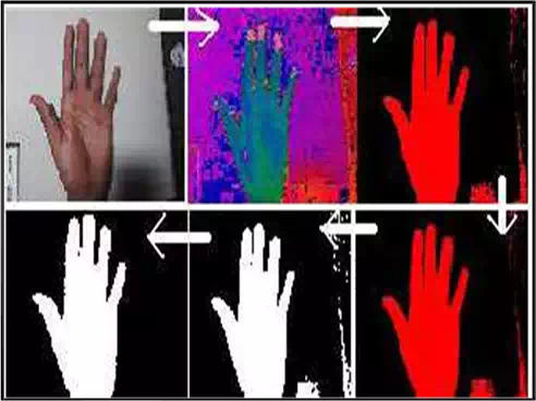 Fig. 4. Binary Image formation (a) Target image (b) HSV conversion (c) Filtered image
(d) Smoothened image (e) Binary image (f) Biggest BLOB
To remove these errors, the biggest BLOB (Binary Linked Object) method was applied to the noisy image [24][25]. The error free image is shown in figure 5. The only limitation of this filter was that the BLOB for hand should be the biggest one. In this, masking background would be illuminated, so false detection is not possible from the background [7][10].
Second step is to extract object of interest from the frame. In our case, object of interest is the part of human hand showing gesture [29]. For this, extra part, other than the hand, is cropped out so that pattern matching can give more accurate results [12]. For cropping extra parts row and column numbers are determined, from where object of interest appears. This is done by searching from each side of binary image and moving forward until white pixels encountered are more than the offset value [25]. Experimental results show that offset value set to 1% of total width gives better result for noise compensation. If size of selected image is mXn then:
Hor_offset= m/100 (7)
Ver_offset=n/100 (8)
Min_col= minimum value of column number where total number of white pixels are more than Hor_offset.
Max_col= maximum value of column number where total number of white pixels are more
than Hor_offset.
Min_row= minimum value of row number where total number of white pixels are more than
 Ver_offset.
Max_row= maximum value of row number where total number of white pixels are more than Ver_offset.
Fig. 5. Error free image
Figure 6 shows Min_row, Max_row, Min_col, and, Max_col for the selection of the boundary for cropping of hand.
Third step is to remove parts of hand not used in gesture i.e. removal of wrist, arm etc. As these extra parts are of variable length in image frame and pattern matching with gesture database gives unwanted results. Therefore, parts of hand before the wrist need to be cropped out.
Statistical analysis of hand shape shows that either we pose palm or fist, width is lowest at wrist and highest at the middle of palm. Therefore extra hand part can be cropped out from wrist by determining location where minimum width of vertical histogram is found. Figure
7.c and 7.d show global maxima and cropping points for hand gestures in figure 7.a and 7.b respectively.
Cropping point is calculated as:
Global Maxima = column number where height of histogram is highest (i.e. column number for global maxima as shown in figure 7).
Cropping point = column number where height of histogram is lowest in such a way that cropping point is in between first column and column of Global Maxima
If gesture is shown from opposite side (i.e. from other hand), then Cropping point is searched between column of Global Maxima and last column. Direction of the hand is detected using continuity analysis of object during hand gesture area determination. Continuity analysis
shows that whether the object continues from the column of Global maxima to first column or to last column. i.e. whether extra hand is left side of palm or right side of palm.
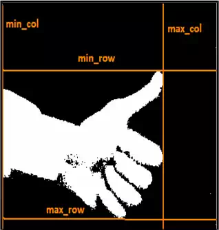
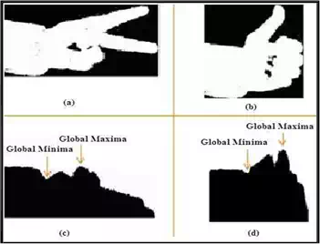 Fig. 6. Boundary selection for hand cropping
Fig. 7. Histogram showing white pixels in each column, with cropping point for hand gesture
Determining the gesture by resizing and pattern matching
Cropping results in a frame of 60×80 pixels, so that the gesture can be compared with the database. This particular size of 60×80 is chosen to preserve the aspect ratio of the original image, so that no distortion takes place.
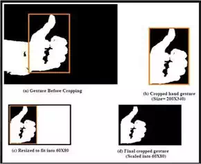 Figure 8.b shows cropped hand gesture from figure 8.a. and figure 8.c. shows the result of scaling and fitting 8.b within 60X80 pixels. Figure 8.d represents final cropped and resized gesture of desired dimension.
Fig. 8. Scaling cropped hand gesture to fit into desired dimension
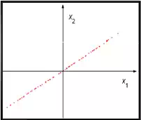 (a) (b) Fig. 9. (a) PCA basis (b) PCA reduction to 1D
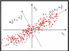
(a) The concept of PCA. Solid lines: the original basis; dashed lines: the PCA basis. The dots are selected at regularly spaced locations on a straight line rotated at 30degrees, and then perturbed by isotropic 2D Gaussian noise. (b) The projection (1D reconstruction) of the data using only the first principal component.
There are many different algorithms available for Gesture Recognition, such as principal Component Analysis, Linear Discriminate Analysis, Independent Component Analysis, Neural Networks and Genetic Algorithms.
Principal Component Analysis (PCA)[11] is used in this application to compare the acquired gesture with the gestures available in the database and recognize the intended gesture.
Calculate number of images which are stored in Training Database
we are considering 10 images in
Training database[12][21]
Convert RGB images into Gray images
RGB images take 3 values for each pixel (RED, GREEN, BLUE) but we want gray scale images.
Calculate size of an image
we are taking image of 100 X 100
Reshaping of an image by converting this into 1-D column vector
A column vector contains data for 1 complete image, so size of each column vector will be 10000 X 1. All images will be stored like this in T Matrix, T grows after each turn. So the final size of T will be 10000 X 10.
 Calculate mean of all images
Mj = (1/P)*sum (Tj), where P is number of images in Train Database, and Tj is the jth image, Mj is the mean of jth image.
Compute the difference image for each image and merge all images
Ai = Ti– Mi , where A represents new difference matrix of images. Size of A will be 10000 X 10
Calculate surrogate of covariance matrix
C=A*A‘
L = A‘*A, A‘ is transpose of matrix A Size of L will be 10 X
10
Calculate Eigenvalues and Eigenvectors
[V D] = eig (L), Diagonal elements of D are Eigenvalues for both L=A‘*A and C=A*A‘
| Sorting and eliminating eigen values | All eigenvalues of matrix L are sorted and those less than a specified threshold are eliminated. So the number of non-zero eigen vectors may be less than (P-1).Let us consider for discussion’s sake that it is P-1 i.e. 9 here. |
| Calculate Eigenhands | Eigenhands = A*L_eig_vec. Eignevhands is centered image vector, Size of Eigenhands is10000 X 9 |
| Projected Train Image | temp= Eigenhands‘*A (: i); Projection of centered images into face space. Temp grows after each turn.Projection of all centered images will be stored inProjected Train Images |
| Size of Projected Train Image is9 X 9 | |
| Extracting the PCA features from test Projected test image | Reshape test image, Calculate difference by subtracting mean of Train images from test image for which we are calculating equivalent image. |
| Calculate Projected Test Image by Eigenhands‘*Difference.Size of Eigenhands is 10000 X 9, size of difference is 10000 X 1So, size of project test image will be 9 X 1 | |
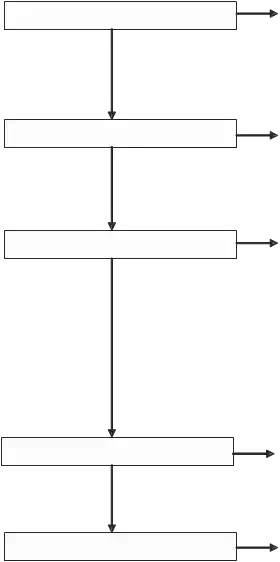
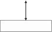 Fig. 10. PCA Algorithm steps for 10 Images
The concept of PCA is illustrated in Figure 9; The graph shows data that originally has two components along the x1 and x2 directions. This is now resolved along the Φ1 and Φ2 directions. Φ1 corresponds to the direction of maximum variance and is chosen as the first principal component. In the 2D case currently being considered, the second principal component is then determined uniquely by orthogonality constraints; in a higher- dimensional space the selection process would continue, guided by the variances of the projections.
A comprehensive explanation of the above scheme for gesture recognition[19] within a database of ten images is given in figure 10. For simplicity of calculations and ease of understanding, each figure is taken to be of size of 100X100 pixels. This algorithms was tested on a PC platform.
Generation of control Instructions for a robot
Different functions corresponding to each meaningful hand gesture are written and stored in database for controlling the robotic Arm. For implementation of robotic arm control, PUMA robotic model has been chosen. Since this model was only available at the time of interface, hand gestures are used to control the various joints of the arm. However, these gestures can be used to control the robotic hand also. Altogether 10 different hand gestures are related to 10 different movements of robotic arm. Movement commands are written as a function in robot specific language. Whenever a gesture is matched with a meaningful gesture from the database, the instruction set corresponding to that gesture is identified and passed to robot for execution. In this way the robotic system can be controlled by hand gesture using live camera. Figure 11 shows movements of robotic hand corresponding to four different specific hand gestures.
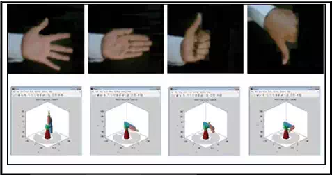
Fig. 11. Movements of PUMA 762 corresponding to some specific hand gestures
However, there are a total of 10 actionable gestures, and one background image for resetting purpose that have been identified as shown in fig. 12.
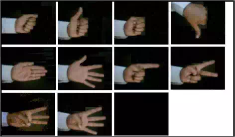 Fig. 12. Set of specified gestures used for robot control
Implementation on FPGA processor
We have implemented the algorithm on an FPGA, using a Database of 6 images. Each image size is 60X80 pixels. The reduction in number of images, image size and its resolution are due to FPGA memory constraints. The MATLAB code produces 6×6 projection vectors which are stored in the RAM of the FPGA using a JTAG cable [27]. After formation of the database, the system captures an image and projection vector of 6×1 is produced and that is given to the hardware for further processing. The hardware is responsible for calculating the Euclidian Distance [ED] with a dedicated block which we designate as ED block [34]. Then the minimum distance [MD] is found using a dedicated block named MD block. And the index corresponding to the minimum distance is returned to MATLAB to display the matched image from the Database [33]. The whole process is shown in fig. 13.
The main drawback of this implementation is that only part of the algorithm resides on FPGA and rest of the algorthim still runs on PC. Therefore it is not standalone system and requires interface with the PC[13]. FPGA implementation of PCA algorithm is a great challenge due to the limited resources available in commercial FPGA kits. But it is quite important to have a complete system on a FPGA chip [40]. As far as the technology is concerned, FPGA is most suited for implementation of real time image processing algorithm. It can be readily designed with custom parallel digital circuitry tailored for performing various imaging tasks making them well-suited for high speed real time vision processing applications[35].
Conclusion
Controlling a robot arm, in real time, through the hand gestures is a novel approach. The technique proposed here was tested under proper lighting conditions that we created in our laboratory. A gesture database consisting of binary images of size 60 X 80 pixels is pre- stored, so it takes less time and memory space during pattern recognition. Due to the use of cropped image of gesture, our database becomes more effective as one image is sufficient for one type of gesture presentation. So, neither we need to store more than one image for same gesture at different positions of image, nor have we to worry about positions of hand in front of camera. Experimental results show that the system can detect hand gestures with an accuracy of 95 % when it is kept still in front of the camera for 1 second.
Image
Acquisition
PCA Eigenvector
Stored in
RAM
 Image
Image
Acquisition
PCA Eigenvector
Gesture
Recognition
Minimum
Distance
RAM
Fig. 13. Recognition process