Medical robotics is an exciting and relatively new field. Robotics plays an important role in medical engineering. Medical robots were initially used in the 1980s, in the field of urology. Robotic arms were developed and used for prostate resection. They can also be highly specialized and assist in diagnosing and treating patients. While there is still much more work to be done, using robots can enhance medical treatments in terms of both the quality and accessibility of care. Using robots can help reduce human error and bring highly specialized information to remote areas without requiring physicians’ direct intervention.
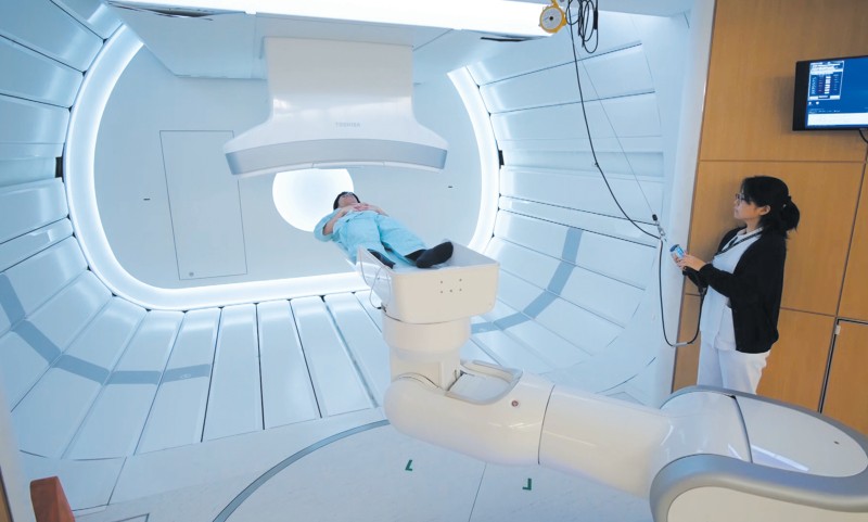
In radiation therapy, high-energy radiation from x-rays, gamma rays, neutrons, and other sources has been used to kill cancer cells and shrink tumors. Radiation may come from a machine outside the body (external-beam radiation therapy), or it may come from radioactive materials placed in the body near cancer cells (internal radiation therapy, implant radiation, or brachytherapy).
The usage of robotic systems to improve the cancer treatment outcome is a new field. This field overlaps with electronics, computer science, artificial intelligence, mechatronics, nanotechnology, and bioengineering. For this purpose, robots can be used in medical facilities to perform different tasks such as delivering radiation sources, real-time tumor tracking during radiation delivery or external beam delivery.
The only product in the market for robotic radiotherapy is CyberKnife Robotic Radiosurgery System. The robotic system has provision for so-called real-time tracking during beam delivery. The device itself is a 6MV linear accelerator mounted on a six degree-of-freedom (DOF) Keller und Knappich Augsburg (KUKA) industrial robot. This system has real-time image-guided control. Consequently, there is a significantly long time delay (about 200 ms) between the acquisition of tumor coordinates and repositioning to the linear accelerator. The CyberKnife-KUKA robot with linear accelerator end-effector is suited for radiation therapy to any body sites. Its field size is restricted to the limited geometry of 12 discrete circular fields ranging from 5mm to 60mm in diameter. Therefore, the workspace is confined and the radiation therapy community has not fully embraced the idea of using an industrial articulated robotic manipulator yet.
The details about CyberKnife robotic system are not included in this chapter. Consequently, the basic idea is to present the novel research results in the field of robotic radiation therapy and its applications.
Brachytherapy robotics
Brachytherapy is a method of treatment in which sealed radioactive sources are used to deliver radiation at a short distance by interstitial, intracavitary, or surface application. With this mode of therapy, a high radiation dose can be delivered locally to the tumor with rapid dose falloff in the surrounding normal tissue.
Recently, several research groups have reported the investigation and development of the robotic systems for the prostate seeds implants, (Stoianovici et al., 2003), (Wei et al., 2004), (Fichtinger et al., 2006), (Yu et al., 2007), (Meltsner, 2007), (Meltsner et al., 2007), (Stoianovici et al., 2007), (Podder et al., 2007), (Salcudean et al., 2008), (Lin et al., 2008), (Moerland et al.,2008). The potential advantages of the robotic seed implants include improving the accuracy of the needle placement and seed delivery, as well as improving the consistency of the seed implant. In medical, especially prostate brachytherapy, applications of robots, precise end- effector position, steady state and positioning accuracy is required. In such applications, even small positioning errors at the manipulator end-effector can have dangerous and costly consequences, (Mavrodis et al., 1997). To achieve the enhancements of the robotic seed delivery, the robots need to be calibrated. Properly calibrated robotic systems have higher absolute positioning accuracy and the deposited seeds positions correspond better to the ones calculated in the planning systems. The brachytherapy robots are usually ultrasound (US) or magnetic resonance imaging (MRI) guided. Generally, to improve needle placement and seed deposition in brachytherapy procedure several methods have been presented in the literature, such as parameter optimization, different needle rotation techniques, robotic insertion, force modeling, and needle steering techniques. Robot assisted therapeutic delivery systems are attractive for several reasons. The potential advantages are increased accuracy, reduced human variability, reduction of clinician’s fatigue and reduction of operation time.
There can be two methods for robotic needle insertion and seed deposition: single-channel approach and multi-channel approach. In single-channel approach one needle can be inserted at a time and typically 2-5 seeds along the needle track are deposited in the prostate according to dosimetry plan. On the other hand, multi-channel system is capable of placing several needles at the time. Thereby, seed delivery can be faster. Since prostate is not rigidly mounted, it can move and rotate as well as unpredictably deform. When several needles are inserted concurrently, prostate will be uniformly pushed back symmetrically to more stable position and deformation of the tissue can be better estimated for precise delivery.
In the following sections two brachytherapy robotic systems has been presented. Both robotic systems: single-channel and multi-channel systems have been designed, developed and manufactured in our research laboratories.
Single-channel brachytherapy robotic system
We have designed and developed a robotic system, named Endo-Uro Computer Lattice for Intratumoral Delivery, Implantation, and Ablation with Nanosensing (EUCLIDIAN). The system consists of a surgical module, a positioning module and a electronic housing, as in Fig.
1.a. Kinematic Denavit-Hartenberg (DH) parameters of the system are presented in Fig.1.b.
The platform connects the surgical module to the cart. The platform has provision for both translational and rotational motion. The vertical lift of the surgery module is motorized for ease of operation against gravitational effect. The supporting platform connects the surgical module to the cart. The surgical module consists of two robotic manipulators, i.e., two open kinematic chains called needling mechanism and an ultrasound probe driver with five and two DOF, respectively.
 a)
a) 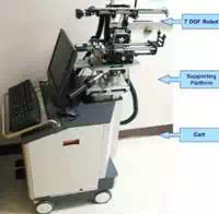 b)
b) 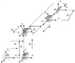
Fig. 1. a) EUCLIDIAN – image-guided brachytherapy robotic system; b) Kinematic DH
schema with reference frames
System description
The three main subsystems of the surgical module, Fig. 2, are: 1) Two DOF transrectal ultrasound (TRUS) probe driver, three DOF robotic gantry, and two DOF needle inserter (denote by needling mechanism in Fig. 21.) with seed holder and seed pusher.
A brief description of these subsystems is provided in the following sections. The TRUS probe, which contains two transducers, transverse and sagittal planes can be translated and rotated separately by two motors fitted with high-resolution optical encoders. This enables imaging the prostate in transverse as well as in sagittal planes with variable slice thicknesses or intervals, as thin as 0.1 mm.
Working ranges of motion of the TRUS probe are 0–185 mm and -91° to +91° in translation and rotation, respectively. The TRUS probe can also be operated manually using the knobs; during this mode, the motors are disengaged automatically by electric clutches. There is a provision for a template holder at the end of the TRUS probe driver, enabling manual takeover if required. A pair of prostate stabilization needles can be placed with angulation in both sagittal and coronal planes to prevent the obstruction of robotic needle insertion. This approach has also been shown to produce significant improvement in prostate immobilization.
This subsystem, which features two translational motions, x and y direction, and one rotational motion (pitch, i.e., the rotation upward or downward about the x-axis), connects the needle driving module to the positioning platform. The motions are achieved by motors and optical encoders fitted with the motors, Figs. 1 and 2.
The range of motion is 62 mm – 67 mm in the x-y direction. The rotational range for angulating the needle is -5° to +5° to avoid pubic arch interference and to reach the target region close to the TRUS probe. The TRUS probe motion and the rest of the surgery module (gantry and needle driver) is decoupled, as they are two separate open kinematic chains, which allow independent motions of the TRUS probe and the needle.
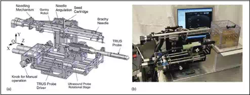 Fig. 2. Surgical module of EUCLIDIAN

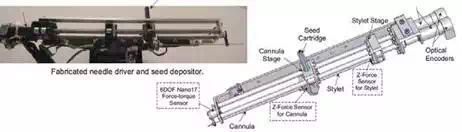
Fig. 3. Needle driver and seed depositor of EUCLIDIAN robot
The needle driver is the most complex subsystem of the EUCLIDIAN, Fig. 3, as the degree of complexity is increased with the introduction of three force-torque sensors, stylet sensor, cannula sensor, and whole needle sensor for cannula rotation and autonomous seed delivery system. The main components of this subsystem are: 1) stylet driver, 2) cannula driver, 3) seed-cartridge holder, and 4) force-torque sensors. The cannula and the stylet are driven separately by two motors. The travel ranges of both the cannula and the stylet are 0–312 mm. During the surgical procedure, the motions of the cannula as well as of the stylet are autonomous in accordance with the treatment plan; however, the clinician must approve the movements at critical points. Our custom-designed seed cartridge can hold 35 radioactive seeds. Accommodation of additional seeds posed some challenges for smooth functioning of the seed cartridge due to spring nonlinearity. However, after careful investigation and adjustments, the seed cartridge is working satisfactorily.
The seed pusher, a flat ended stylet, is deployed to expel the seed out of the cartridge and to deposit it at the planned location. Every motion during the sequence of seed delivery is fully automatic; however, the clinician is able to interrupt and/or manipulate the movements at any time using a hand pendant. By monitoring the force data from the sensor installed at the proximal end of the stylet, Fig. 4, the seed removal from the cartridge to the cannula can be verified. A ten-button hand pendant provides the clinician with the authority and freedom to assert control of the surgery module at any desired time. That is, the clinician can command each of the motors for manipulating the motion of various components of the surgical module, such as needle insertion, needle rotation, seed deposition, x-y movement of the gantry, and system abort.
The three DOF cart (two translations and a rotation about the vertical axis) provides gross
movement of the robotic system to align with the patient, while the six DOF platform enables finer movement for desired positioning and orientation of the robot in three- dimensional (3D) space.
The computer, system electronics, and cable junctions are housed in the electronics housing, Fig. 1. The EUCLIDIAN’s surgery module is fully autonomous; all the motors are fitted with high-resolution optical encoders and precision gear boxes. The robot is controlled by an industrial computer, which is proven to be robust and reliable for working in harsh industrial environments and military applications. It has a special metallic casing for minimizing electromagnetic interferences.
Two Galil control cards, Model DMC- 1842; Galil Motion Control, Inc., Rocklin, CA, are used: One card to control the TRUS probe driver and gantry motions and the other card to control the needle driver and the seed pusher. A robust and stable proportional, integral and derivative (PID) controller has been developed for controlling the motorized surgical module. We have tuned the PID gains in such a manner so that the system’s stability is maintained when the needle changes its states from merely position control in the air to both position and force control mode in the patient’s body. The needle can be driven at a maximum velocity of approximately 100 mm/s; however, a lower velocity, 60 mm/s, setting is used as the default. A frame grabber, FlashBus, Integrated Technologies, Indianapolis, IN, is used for TRUS image capturing. Three force-torque sensors , Nano17, ATI Industrial Automation, Apex, NC and M13, Honeywell, Morristown, NJ, are used for needle insertion force monitoring and robot control feedback. Each of the motors is fitted with an optical encoder, MicroMo Electronics, Inc., Faulhaber Group, Clearwater, FL, which can provide final motion resolutions, considering gear ratios and screw leads, of 0.0007 mm for gantry x- y translations, 0.004 mm for stylet and cannula motions, and 0.005 mm and 0.06° for TRUS probe translation and rotation, respectively.
Advanced control techniques
In the previous studies, it was concluded that the proper selection of the translational and rotational velocities may reduce tissue deformation and target movements by reducing insertion force, (Buzurovic et al., 2008.a). Therefore, it can be concluded that the insertion force has a dominant influence on the needle insertion, seed deposition precision, and dosimetry distribution in brachytherapy procedure. In our initial work, (Buzurovic et al.,2008.b) we have investigated tracking problem for the same robotic system using neural network approach. The force prediction model was introduced as well. In this article we have introduced novel methods to control the brachytherapy robot with the lowest tissue deformation and highest seed precision delivery as the ultimate goals. In order to achieve the desired dynamic behavior of the robotic system, the control strategies that we implemented in the robotic system have a force prediction module. For the first one we have used an artificial neural network (ANN) and neural network predictive control (NNPC), (Buzurovic et al., 2010.a).
In the following part the use of a feedforward model predictive control (MPC) was described. The purpose of this approach is to control the reactive force which is responsible for tissue displacement. Also, as the second control task was to predict and compensate the impact of the measured and unmeasured disturbances rather than waiting until the effect appears at the output of the system on the other side. When the reactive force is minimized, tissue displacement decreases. The force prediction control was also used to minimize the effect of system time-delay. Because of the fact that this procedure required an accurate robot system model, it was necessary to obtain a more precise model. That is a reason for adopting the robotic system model as a singular system of differential equations.
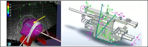
Fig. 4 represents the contact surface where reactive force appears during surgery. A mathematical equation of contact surface is calculated using EUCLIDIAN robotic system software.
 Φ(p)=0
Fig. 4. a) 3D representation of the contact surface (prostate gland) during insertion. b) 5DOF surgical module. Absolute and local coordinate systems together with generalized coordinates qi
Assume that the contact surface is a scalar functionΦ: Rm→R1, Fig. 4a.
Φ(p) = 0
(1)
The contact force vector is:
f = DT (p)λ (2)
λ is a scalar multiplier for the constraint function and D(p) is the gradient of the constraint function, described as in (3),
D( p) = ∂Φ(p)
∂p
(3)
In the previous equation p∈ℜ3 is a position vector from the fixed reference frame to the constrained surface. Additional constraint is p=Φ(q) at the contact point. The matrix function J(q) is defined as the Jacobian matrix function.
J(q) = ∂Φ (q)
∂q
(4)
The influence of the contact force to the system can be described as
M(q)q + G(q , q) = τ + JT (q) f (5)
where M(q) denotes the inertia matrix function and G is the vector function which describes coriolis, centrifugal and gravitational effects. q is a vector of the generalized coordinates and τ is the torque vector. Influence of the external contact forces is described by factor f. Combining equations (1)-(5) the mathematical model of the system is
M(q)q + G(q , q) = τ + JT (q)DT ( M(q))λ(q , q ,τ )
(6)
After an appropriate transformation, equation (6) is transformed to its matrix form
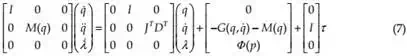
System (7) is linearized at the surrounding point where the needle is inserted into the patient. The linearized mathematical model of the system is obtained, as follows
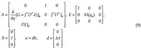
Ex(t) = Ax(t) + Bu(t) + d (8)
with singular matrix E∈ℜn×n, and vector d which represents the unmeasured disturbances such as needle deflection, tissue deformation and displacement, A∈ℜn×n, B∈ℜm×r. x and u represent the system state-space vector and control vector, respectively, x∈ℜn, u∈ℜr.
The system defined by (8) is known as a singular system, descriptor system, semi-state system, system of differential-algebraic equations or generalized state space system. They arise naturally in many physical applications, such as electrical networks, aircraft and robotic systems, neutral delay and large-scale systems, economics, optimization problem and constrained mechanics. The matrices of linearized system (8) are defined as follow
Now it is possible to find subspaces S and F, as in (Buzurovic et al., 2010.a), having in mind that for state space X the system equation (8) can be represented as the direct sum of S and F, X= S ⊕ F. As a result of the matrix transformation M applied to system (8), the slow and fast subsystems can be described by a mathematical formulation
x s = Ls xs + Bs u + ds
L f x f = x f + Bf u + d f
(10)
with Ls = MA|S, Lf =MA|F, Bs=PMB, Bf=QMB, ds=PMd and df=QMd for some linear transformations Q and P represented by matrices Q and P, respectively. For that case, the
initial conditions are chosen to satisfy x0s=P x0 and x0f=Q x0. The solution of system (10) is
x=xs+ xf
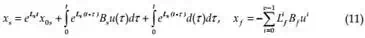
Now it is possible to apply the MPC control, Fig. 5, and to investigate dynamical behavior of the system. Disturbance d is given to MPC and its effect is predicted and compensated before the effect appears at the system output.
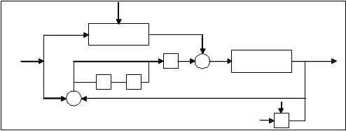
Fig. 5. Insertion force control scheme for the slow subsystem
In (Mills, 1988) is shown that the impulsive behavior of the system can be avoided using appropriate initial conditions, defined by x0s=P x0 and x0f=Q x0. By using the described approach the fast subsystem will not induce impulsive behavior. Moreover, it can be concluded as stated previously and from equation (11) that there is little need to find fast feedback to eliminate the impulsive behavior. The necessary task was to find an appropriate feedback for the slow subsystem. The control scheme for the slow subsystem is represented in Fig. 5, as suggested in (Cobb, 1983).
Furthermore, when the MPC controller is applied, the main objective is to hold the insertion force at the predefined acceptable reference value, by adjusting the control signal from actuators in order to minimize the prostate displacement, i.e. the reactive force which acts upon the tissue. Using this approach it is possible to decrease the insertion force during insertion trajectory. The needle displacement is an unmeasured disturbance and the controller provides feedback compensation for such disturbances. For the insertion force the controller provides feedforward compensation. Various noise effects can corrupt the measurements. The noise could vary randomly with a zero mean, or could exhibit a non- zero, drifting bias. The MPC uses a filtering method for removing estimated noise component. At the beginning of each sampling instant, the controller estimates the current system state. Accurate knowledge of the state improves prediction accuracy which improves controller performances.
During the insertion passive force control becomes active and keeps passive insertion force close to the predefined minimal value. When the MPC control approach was implemented it is possible to decrease the insertion force, as it is shown in Fig. 6. Also, peaks during the insertion are minimized. These conclusions give us a reason to believe that tissue deformation can be decreased better than using the traditional PID control.
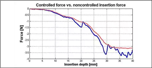
Fig. 6. Controlled force with MPC (red) and insertion force with PID controller (blue)
Multi-channel brachytherapy robotic system
Multi-channel system is capable of placing several needles or even all needles at a time and thereby, it can be faster in delivering the seeds required for the treatment. A multi-channel delivery system can effectively avoid the problem of gradual prostate swelling (i.e., edema) and deformation, which occurs while depositing the seeds by single needle. Since the prostate is not rigidly mounted, the prostate can move and rotate as well as deform quite unpredictably, at every time a needle is inserted. But, when several needles are inserted concurrently, the prostate will be uniformly pushed back symmetrically to a more stable position and the deformation can better be estimated for precise delivery of seeds. Thus, the multi-channel system can overcome some of the drawbacks that may be encountered by the single-channel robotic systems. In this part, we present our Multichannel Image- guided Robotic Assistant for Brachytherapy (MIRAB), which is designed and fabricated for prostate seed implantation. Currently, MIRAB can simultaneously rotate and insert 16 needles. The MIRAB is capable of inserting more needles concurrently, if needle rotation is excluded.
System description
The MIRAB system shown in Fig. 7 consisted of five modules: (1) Rotary Needle Adapter, (2) Surgical x-y Carrier, 3) Mounting and Driving Mechanism, (4) Seed Applicator, and (5) Transrectal Ultrasound (TRUS) Driver, (Podder et al., 2010).
Rotary Needle Adapter can hold 16 needles with rotational capability. However, additional needles can be installed without provision for rotation. Two direct current (DC) motors rotate the needle using a spur- gear train. It is known that provision of needle rotation reduces the insertion force as well as organ (or target) deflection and deformation. For guiding the extended needles (brachytherapy needles are about 200mm in length and 1.27mm or 1.47mm in diameter) a regular brachytherapy template is installed at the distal end.
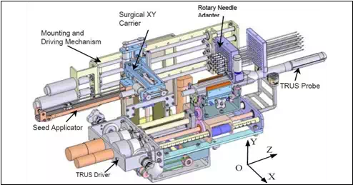 Fig. 7. MIRAB robotic system
The needles can be simultaneously inserted using one of the DC motors on the Mounting and Driving Module. Surgical x-y Carrier is 3-DOF module carries the Seed Applicator which delivers seeds and withdraws needle. Two DC servo motors on the x-y carrier provide motions to the Seed Applicator in x- and y-direction, while another DC servo motor on the Mounting and Driving module provide motion in the z-direction, i.e. the depth. Mounting and Driving Mechanism is driven my two DC servo motors to impart translational motion (along z-direction) to the Needle Adapter and Surgical x-y Carrier. Seed Applicator is a module which is attached to the Surgical x-y Carrier. A DC servo motor is employed to expel the seed from the seed cartridge. Transrectal Ultrasound (TRUS) Driver is a module was originally developed for EUCLIDIAN system, Fig. 2). However, the MIRAB is designed in a way so that it can be installed on the EUCLIDIAN by taking the needling module away from the EUCLIDIAN away. This interchangeability is of MIRAB and EUCLIDIAN will be very convenient to switch from a single-channel system to a multichannel system. TRUS can image the prostate and the relevant anatomies in transverse as well as sagittal planes.
All the DC servo motors are fitted with high-resolution (up to about 0.0007mm) optical encoder, MicroMo Electronics, Inc., Faulhaber Group, Clearwater, FL. An industrial computer, Plans, San Diego, CA, is used for controlling the whole system. Two Galil control cards, Model DMC-1842; Galil Motion Control, Inc., Rocklin, CA, are used. All the desired motions are achieved by deploying a Proportional, Derivative and Integral (PID) controller.
Experimental results
The purpose of the following experiments is to evaluate performances of multichannel robotic brachytherapy system designed for prostate seed implantation.
The developed multichannel robotic system is capable of inserting large number of needles concurrently and depositing seeds automatically.
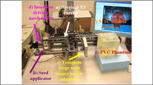 Fig. 8. MIRAB robotic system, experimental setup
The experimental procedure, Fig. 8, is described in the following part. For cannula, we used 18ga x 20cm Stainless steel BARD needle and for stylet Rev. A4, 304 Stainless steel needle Vita Needle Company. Phantom was prepared from polyvinylchloride (PVC) plastic and PVC+ hardener in the ratio 80% to 20%, respectively, MF Manufacturing, TX. Force measurements were performed using single-axis force sensor, Model 13, Honeywell Sensotech, Columbus, OH, installed on proximal end of the cannula. Deposited seeds were rounded stainless steel dummy seeds, BARD. Position of the tip of the needle and consequently depth of the deposition into the phantom was measured using optical encoders FAULHABER MicroMo HEDM5500J series 5500, attached to the template stage and seed applicator motors. The MIRAB was evaluated for insertion speed of 5mm/s,10mm/s, 20mm/s, 40mm/s, 60mm/s and 80mm/s and stylet speed in the range of 20-60 mm/s. For each insertion speed we recorded force for 1, 2, 4, 8 and 16 needles installed together on the template stage.
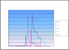
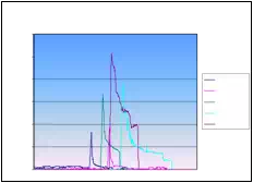
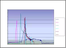
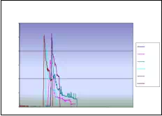
Absolute seed placement error was 0.10mm (SD=0.11mm) in X and Y direction and 0.15mm (SD=0.12mm) in Z direction for plan with 16 needles and 64 seeds. Relative position error between seeds were 0.07mm (SD=0.05mm). It can be seen in Fig. 9.a that maximum insertion force for insertion speed of 40mm/s was in the case when 16 needles were inserted together. For that case, maximum force value was 43N. Fig. 9.b represents the insertion force for the insertion speed of 80mm/s. Maximum insertion force for 16 needles was 52N. It can be concluded that more needles were inserted in one insertion the force value was higher. But when 8 needles were inserted in the same time maximum insertion force did not change. For insertion speed of 40mm/s and 80mm/s the insertion force was around 35N. In Fig. 9.c and Fig. 9.d insertion force for whole range of the insertion speed were represented. In the former case 8 needles were inserted together while in the latter 16 needles were inserted. The insertion force for the latter case was about 7N higher due to bigger number of the inserted needles. However, it can be noticed that force does not significantly change in the range of insertion speed higher that 40mm/s (60mm/s or 80mm/s). The conclusion based on this fact is that insertion speed can be divided into two regions with different insertion parameters.
It can be concluded that the average maximum insertion force was less then 45N for moderate speed range (insertion speed 40mm/s and stylet speed 30mm/s, 16 needles in the stage) and 52N for high speed range (insertion speed greater then 40mm/s and stylet speed 50mm/s, 16 needles in the stage). Insertion time per seed was 5-8 seconds. Plan delivery time for high speed range was 8min and 12min for moderate speed range.
The summary of conclusion is as follows. It was observed that more needles were inserted together force value was higher. However, when 8 and 16 needles were inserted in the same time maximum insertion force did not change. Furthermore, force did not change significantly in the range of insertion speed higher than 40mm/s. Consequently, insertion speed range can be divided into two regions with different insertion parameters. Preliminary results reveal that MIRAB is efficacious for delivering seed accurately. MIRAB can potentially be used for image-guided robotic brachytherapy.
Insertion force for insertion speed of 40mm/s
Insertion force for insertion speed of 80mm/s
50 60
45
40
35 1 needle 40
![]() 30 2 needles
30 2 needles
![]() 25 4 needles 30
25 4 needles 30
20 8 needles
15 16 needles 20
10
5
0 0
1 needle
 2 needles
4 needles
8 needles
16 needles
Insertion force for 8 needles
Insertion force for 16 needles
50 60
45
40 50
35 5mm/s
![]()
![]() 30 10mm/s
30 10mm/s

 20mm/s
40mm/s
20 60mm/s
15 80mm/s
10 10
5
0 0
5mm/s
10mm/s
 20mm/s
40mm/s
60mm/s
80mm/s
Fig. 9. a) Insertion force for different number of needles installed on the template stage, for insertion speed of 40mm/s. b) Insertion force for different number of needles installed on the template stage, for insertion speed of 80mm/s. c) Insertion force for different insertion speed;8 needles inserted in the same time. d) Insertion force for different insertion speed; 16 needles inserted in the same time
Robotic systems for real-time tumor tracking
Respiratory and cardiac motions induce displacement and deformation of the tumor- volumes in various internal organs. To accommodate this undesired movement and other errors, physicians incorporate a large margin around the tumor to delineate the Planning Target Volume (PTV), so that the Clinical Target Volume (CTV) receives the prescribed radiation dose under any scenario. Consequently, a large volume of healthy tissue is irradiated and sometimes it is difficult to spare critical organs adjacent to the tumor, (Buzurovic et al., 2010.b,c).
In this section we described a novel approach to the 4D Active Tracking and Dynamic Delivery (ATDD) incorporating tumor motion prediction technique. The proposed algorithm can predict the tumor position and the robotic systems are able to continuously track the tumor during radiation dose delivery. Therefore a precise dose is given to a moving target while the dose to nearby critical organs is reduced to improve patient treatment outcome. The efficacy of the proposed method has been investigated by extensive computer simulation, (Buzurovic et al., 2010.d, 2011.a).
Recently, several research groups are investigating various aspects of tumor tracking and developing tools to deliver precise dose to moving target-volumes, (Ozhasoglu & Murphy, 2001), (Keall et al., 2006.a), (Benchetrit, 2000), (Vedam et al., 2004), (Sharp et al., 2004), (Schweikard et al., 2000), (Kamino et al., 2006), (D’Souza & McAvoy, 2006), (Keall et al.,2006.b), (D’Souza et al., 2005), (Chung et al., 2006), (Podder et al., 2007, 2008), (Buzurovic et al., 2010.d, 2011.a). Generally, commonly practiced methods for compensating target/tumor motion can be structured as: (i) breath-hold techniques, (ii) gating techniques, and (iii) ATDD. The ATDD is the most effective technique, but it is the most challenging one. The ATDD can be accomplished in three different ways: (1) using the multi-leaf collimator (MLC), (2) using the treatment couch, and (3) using the MLC and the couch simultaneously. However, each of them has its own unique limitations.
For instance, MLC gating technique using internal fiducials requires kilovoltage x-ray which delivers unwanted radiation dose to the patient, and additionally gating suffers from severely low duty-cycle (only 30%-50%) and intensity modulated radiation therapy (IMRT) efficiency (only 20%-50%); all these lead to a 4- to 15-fold increase in delivery time over conventional treatment, (Keall et al., 2006.a). Therefore, it is of tremendous clinical interest, if the radiation beam can be delivered with higher duty-cycle (or almost continuously) while compensating for the target movement without exposing the patient to kilovoltage x-ray. Robotic systems can help in a great deal solving this problem.
In the following part we present developed dynamic equations of motion HexaPOD robotic couch. We applied the similar approach to one standard 3DOF robotic couch for radiation treatment (Buzurovic et al., 2010.d). In addition, we presented the control approach and prediction module which is capable of compensating time delay of the mechanical system.
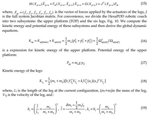
For system dynamics, we used energy based Lagrangian formulation. The Lagrangian function of dynamic systems can be expressed as:
L = Kinetic energy (K) – Potential energy (P) (12) Thus, the general form of dynamic equations is
where, q∈Rn is the vector of generalized coordinates, and τ is the generalized force (or torque) applied to the system through the actuators.
The dynamical behavior of a 6DOF robotic couch, has been investigated. Proposed approach is explained below.
Parallel robotic platform
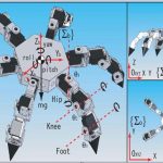
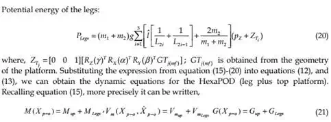
The HexaPOD is a special type of Stewart Platform, i.e., a parallel robotic manipulator. The parallel robotic mechanism consists of a rigid body top plate, or mobile plate, connected to a fixed base plate and is defined by at least three stationary points on the grounded base connected to six independent kinematic legs. Typically, the six legs are connected to both the base plate and the top plate by universal joints in parallel located at both ends of each leg. The legs are designed with an upper body and lower body that can be adjusted, allowing each leg to be varied in length as in Fig. 10.

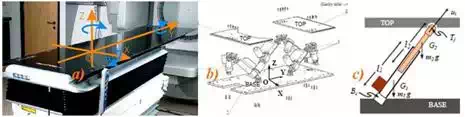
Fig. 10. HexaPOD robotic couch, a) External isometric view with moving coordinate system, b) External schematic view with fixed coordinate system, c) Schematic of the leg
In this study, we have used the following notations for modeling the HexaPOD, i.e. the Stewart platform. Referring figure 2 we have assigned an inertial frame (X,Y,Z) at the center O of the lower platform, i.e. the BASE, and assigned another moving coordinate system (x,y,z) at the center of the top platform, i.e. the TOP. The BASE frame is assigned and called as fixed frame and the TOP frame is moving and is called as moving frame.
To specify the configuration of the 6DOF Stewart Platform, six independent position- orientation variables are needed. Denote the position of the origin of the TOP frame with
| x y |
respect to the BASE frame [ p p p ]T . The orientation is not defined by the standard
z
Euler angles, but by rotating the TOP frame first about the fixed X-axis by α, then about
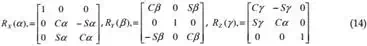
fixed Y-axis by β and finally about Z-axis by γ. We denote RX(α), RY(β) and RZ(γ) as the three matrices that represent three basic rotations as follows:
| p −o x Y , Z |
where C(.) =cos(.), and S(.) = sin(.). This definition of the orientation not only provides us with a clear physical meaning but also avoids violating the one-to-one relationship between the system configuration and the values of Xp-0, which may cause the Jacobian matrix to lose its rank, even if the system is not in a singular configuration. Thus, the position and orientation of the upper platform is specified by the Cartesian coordinate system as X = [ p , p p ,α , β , γ ]T .
Now, the dynamic equations in Cartesian-space (or task-space) are expressed as:
The dynamic equations of motion for HexaPOD robotic couch have been discussed above. These equations are essential in developing our proposed dynamics-based coordinated control system. In the following part it can be seen that the speeds for tracking are slow. However, it was necessary to use dynamical model approach to fulfill strong requirements regarding the tracking accuracy. Since the tracking is impaired with a real-time radiation delivery, it was of the significant importance to have accurate model and to decrease possibilities for inaccurate radiation delivery during tracking.
Control and prediction
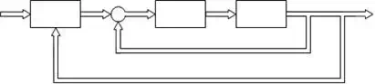
To track the tumor trajectory for optimal dose delivery to the CTV while sparing normal tissue, we propose PID control for HexaPOD parallel robotic platform. The basic goal of the controller was to specify the desired trajectory of the couch for all tumor positions. Block diagram of the decentralized coordinated dynamics-based closed-loop control strategy for HexaPOD robotic couch using prediction module PM, controller C and robotic couch T, is presented in Fig.11.
Xmot Xd ε
PM _
τξηs
 C T
C T
Xξη s
Fig. 11. Control schema for parallel robotic platform
By taking this approach it is possible to compare the dynamical behavior of the one of the most suitable system for 4D tracking. In the proposed approach, the trajectories of the tumor motion in the x, y and z directions were obtained from the 4D Computer Tomography (CT) data of real patients. These task-space trajectories were used to generate joint-space motion trajectories for the robotic systems.
Referring Fig. 11, we have denoted the following parameters: Xmot is raw data of the tumor motion. Xmot is the input into the prediction module (PM). Output of the PM is predicted value of the tumor motion Xd. Dynamic-based controller is denoted by C. Robotic couch is denoted by T. Input to the T module are desired forces values and output is the motion of the robotic table , denoted by Xξηs, which compensate tumor motion.
Dynamic-based controller
To implement the proposed algorithms, we have used a PID control scheme. Dropping the subscripts, we can rewrite equation (21) as
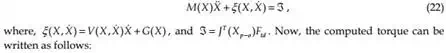
where, KI is the integral gain. Thus, equation (26) ensures asymptotic decay of the transient errors as well as reduction of steady-state errors.
Prediction module
Prediction module PM is developed to predict tumor motion and to compensate errors due to delay in the system response. Prediction module algorithm uses Xmot to calculate predicted value Xd. The system output Xξηs is used for accuracy checking and fine tuning purposes.
Normalized Least Mean Square (nLMS) algorithm is adapted for the dynamic system to predict the position in three dimensions. System delay td is a parameter in the developed algorithm.
The nLMS algorithm belongs to the family of Least Mean Square LMS algorithms. The LMS algorithm is an adaptive algorithm presented by Widrow and Hoff as in (Widrow & Walach, 1994) and (Chen, 1993). The LMS algorithm use iterative procedures to make successive corrections to the weight vector towards the negative direction of the gradient vector. As a result minimal mean square error will be minimized. The LMS algorithm can be summarized as follows:
Input vector is X(n) = [x(n), x(n-1),…, x(n–t+1)]T, where n is the current algorithm iteration and t is the tap number. Desired vector is D(n) = [d(n), d(n-1),…, d(n–t+1)]T. Consequently, predicted vector is Y(n) = [y(n), y(n-1),…, y(n–t+1)] T. Error vector is E(n) = [e(n), e(n-1),…, e(n–t+1)]T. Filter vector W(n) is used to calculate predicted value y(n). It is of the form W(n) = [w(n), w(n-1),…, w(n-t+1)] T. Predicted value is
y(n) = W (n − 1)H X(n)
(27)
where W(n–1)H is the hermitian transpose of W(n–1). Thus, algorithm error is
e1(n) = d(n) – y(n). (28) Now, filter vector becomes W(n) = W(n-1)+µ X(n)e(n), where µ is the learning rate. In order
to ensure the stability of the algorithm it is necessary to adjust LMS to its normalized form nLMS. For the nLMS algorithm the filter vector is:
W (n) = W (n − 1) + µ X(n)e(n)
X(n)H X(n)
(29)
Furthermore, to ensure accuracy of the prediction process, algorithm checks difference between predicted value y(t) and system output Xξηs. We defined
e2(n) = d(n) – Xξηs(n). (30) Finally, prediction module calculates next position of the tumor, based on algorithm which
incorporates nLMS error e1(n) and physical error e2(n). Therefore, the resultant error is sum of the prediction and tracking error.
Simulation
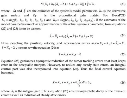
The computer simulation results for HexaPOD robotic couch have been presented in the Fig. 12 through Fig. 13 below. Fig. 12 shows position of the each HexaPOD leg during tracking task. Combined motion of the robotic legs results in tracking the desired trajectory. This means that the robotic couch will start moving the legs according to the desired trajectory, obtained from 4D-CT. Combined motion of the HexaPOD legs will result in patient motion which has opposite direction of the tumor. Consequently, tumor will appear steady and the beam will irradiate smaller PTV which does not include all possible tumor position during the respiratory cycle.

Fig. 12. HexaPOD legs positions during tracking

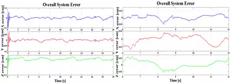 Fig. 13. Overall system errors; a) εX, εY,εZ in X, Y and Z directions for HexaPOD couch. b) The error amplitudes for steady states
An average system error after the transient time was εXH=εYH =εZH= ±0.2mm and 0.4mm for irregular motion pattern, Fig.13. The tracking error cannot be zero, but it can be kept within the tolerable limit.
From the simulation results it appeared that proposed methods could yield superior prediction and tracking of the tumor motion induced by respiratory motion.
Analyzing the simulation results it can be concluded that the robotic system show the same maximum tracking error which was 1mm. Based on dosimetric studies, (Buzurovic et al.,2010.b,c) it was noticed that implementation of real-time tracking techniques can minimize irradiation to healthy tissues and improve sparing of critical organs. It was shown in the studies that the dosimetric effect on PTV and CTV coverage, caused by the prediction error in tumor tracking procedure, is insignificant. Consequently, tumor tracking error for the described proposed method will not compromise patient treatment outcome. Implementation of the proposed technique can potentially improve real-time tracking of the tumor-volume to deliver highly conformal precise radiation dose at almost 100% duty cycle while minimizing irradiation to health tissues and sparing critical organs. This, in turn, will potentially improve the quality of patient treatment by lowering the toxicity level and increasing survival.
In this study, we have deployed a closed-loop PID control. Adaptive control can be a good choice because of the variability in the payload on the system, i.e., the weight of the patient. Results of the adaptive control applied to the proposed system can be found in (Buzurovic et al., 2011.b).
Conclusion
In this chapter the use of the robotic systems in radiation therapy has been presented. It was shown that robotic systems can greatly influence to the current method of radiation therapy in both delivering radioactive material inside the cancerous tissue and in compensation of moving tumors during the external beam radiation therapy. The presented systems are novel and the clinical applications of such systems will be near future in modern cancer treatments. It was shown many times that modern robotics can improve many aspects of human work. The presented robotics systems are the example of the previous statement.