In this chapter, we develop a small-sized lightweight fish-like robot, with its surface composed of a flexible thin plastic film. In robotics, novel designs have been led to advances. For example, designs of tensegrity structures, which are composed of a set of disconnected rigid elements connected by continuous tensional members and have been used to develop lightweight robots such as a crawling robot, a robotic arm, an underwater vehicle, and a fin mechanism. Stream-lined designs of gliding wings have allowed underwater robots to energy-efficient wide-area observations. Some designs such as a manipulator unit and a mechanical contact mechanism, fixed onto a commercial remotely operated vehicle (ROV), have improved inspection efficiency of underwater vehicles for undersea landscape inspection. Novel fabrication methods can also lead to advances in robotics. For example, the microfabrication of soft material has been shown to produce a gecko robot that can climb a wall. Moreover, the use of a composite material resulted in a bee robot that could fly.
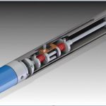
We have applied a vacuum packaging method to fabricating a lightweight fish-like robot. The internal components of this robot consisted of a motor, a drive circuit, a battery, a microcontroller, and an oscillation plate to generate thrust (Figure 1). These components were encapsulated by a plastic film bag using a vacuum packaging machine. Vacuum generators have been studied in various industrial settings, including food packaging, object gripping by a mechanical hand, material formation, and casting materials. In robotics, engineering the utilization of a vacuum has included the construction of robots with suction cups for wall climbing and a handling tool for nanorobots. This research should not only contribute to the development of a fish-like robot but represents the application of a novel fabrication method to robotics.
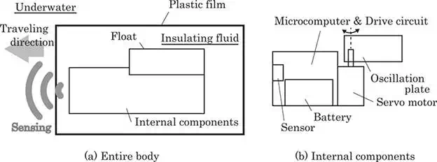
FIGURE 1.
Concept of a fish robot encapsulated by a plastic film.
Recently, small-sized underwater robots are especially required to improve the spatial resolution of these measurements, resulting in high-quality data. Biomimetic designs to improving small-sized underwater robots have included the development of a mechanical pectoral fin, fish-like robots, and snake robots. These robots can swim through water by creating undulations oscillating their bodies. The entire body of the fish-like robot we proposed also generates thrust by the body flexure. The plastic film encapsulating the internal components is inflected by the oscillation plate fixed on the servo motor. To improve the lubricity between the oscillation plate and the plastic film and to simplify the waterproofing and pressure resistance properties of the fish-like robot, its internal components can be filled with insulating fluid.
Most of the underwater robots are encased in a solid, pressure-resistant structure made of metal, such as a stainless-steel and titanium alloy to improve the waterproofing features. The weight of these robots will therefore tend to be greater due to the density of these metal components. To overcome this drawback, we have designed a fish-like robot, the entire outer layer of which is composed of a plastic film, resulting in a lightweight body with low elasticity. In developing the prototype, we selected a low force/torque actuator by utilizing a thin plastic film. This film was flexible, but had lower elasticity for bending than deformable materials such as silicone.
To achieve autonomous control, underwater robots must detect obstacles under water. In traditional underwater robots, sensors such as a camera and a photodetector to detect obstacles are arranged in pressure tight cases. This study was designed to evaluate the electromagnetic-wave-transmitting properties of the thin plastic film. These properties can enable noncontact sensors to be arranged within the encapsulating plastic film (see Figure 1). Similar to the other internal components of our robot, these sensors did not require special waterproofing. Additionally, we were able to easily determine the arrangement of these noncontact sensors because the entire surface of the fish-like robot was composed of an electromagnetic-wave-transmitting film, thus enhancing the design flexibility of its internal components.
Underwater robots also require three-dimensional nonholonomical movement to move over wide areas under water. For underwater robots, several vertical depth control techniques must be implemented, including throwing the ballast and changing the volume. Difficulties may be overcome by attitude changing schemes, including use of a movable weight in the body, a movable float on the body, the reaction force of internal rotors, the gyro effect of a flywheel in the body, and thruster forces for a neutral buoyant underwater robot. This study involved changing the position of the floating block in the robot body, allowing the selection of a low torque motor.
This chapter is organized as follows: the next section briefly outlines the fabrication of an underwater robot encapsulated by a plastic film. This film was applied by a vacuum packaging machine used in the food industry. We also utilized insulating fluid to simplify the pressure resistance properties of the robot. Section 3 discusses the methods used to control our fish-like robot with a plastic-filmed body. We first investigated the performance of an infrared sensor, taking into account the influence of water and a plastic film. We showed that the signals from the infrared sensors could direct simple autonomous locomotion of our robot. We also developed an attitude control mechanism, based on the geography of the floating block in the body filled with insulating fluid. We showed that changes in the densities of the floating block and the insulating fluid can change attitude. Section 4 summarizes our conclusions.
Fabrication
We utilized a vacuum packaging machine to fabricate a fish-like robot, the entire body of which was composed of a flexible plastic film. We called this fabrication robot packaging. Figure 2 shows the process used to fabricate robot packaging. The process can be classified into four steps: (a) encapsulation of the internal components, including a microcontroller, a drive circuit, a battery, a servomotor, and an oscillation plate, in a plastic film bag used to package foods; (b) pouring of insulating fluid, specifically industrial oil or cleaning fluid for semiconductors, into the plastic bag. This would reduce the quantity of air in the package after the insulating fluid was defoamed and packaged; (c) defoaming the inside of the robot using a vacuum packaging machine; (d) sealing of the plastic film by a sealer within the chamber of the vacuum packaging machine after defoaming. The drive circuit in the body of the robot is not shortened by the insulating fluid surrounding the circuit. Using this method, we were able to easily fabricate the entire body of a fish-like robot at low cost and in a short time because the body of the robot consisted of only a thin plastic film, which was sealed by a vacuum packaging machine to form the entire body of the robot.
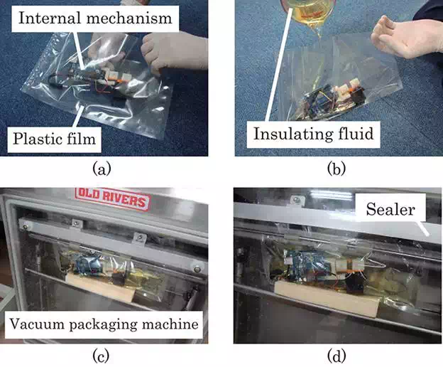
FIGURE 2.
Fabrication process of the robot packaging method.
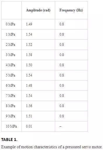
Ideally, a plastic film fabricated by a robot packaging method does not break in response to water pressure because the pressure inside the robot is equal to the environmental pressure. The plastic film and the insulating fluid are deformed slightly by water pressure; however, the volume of the insulating fluid does not change markedly due to its high incompressibility. To assess the validity of robot packaging, we can test the pressure resisting feature of a servo motor encapsulated by a transparent plastic film. The pressure test is performed using a transparent acrylic cylindrical pressure tight case, to which a pump funneled water. The pressure tests are performed using images captured by a camera due to the transparencies of the plastic film and the tight case. These images are used to investigate the pressure resistance properties of these robots, based on frequency analyses of movement of the servo motor. Table 1 shows the motion characteristics of a servo motor (RS304MD; Futaba) with a servo horn at 1 MPa pressurization steps. The angle of the servo horn was determined by the positions of the center of rotation and the LED mounted onto the tip of the servo horn. The amplitudes in Table 1 were the average amplitudes and the frequencies of the servo horn were computed by frequency analysis utilizing fast Fourier transformation (FFT). As shown by the amplitude in Table 1, however, the motor could not move in an environment pressurized at 10 MPa. The frequency calculated by FFT at 10 MPa was not used because the power spectrum was much smaller than the other estimated frequencies at up to 9 MPa in Table 1.
Control
AUTONOMOUS CONTROL BY SENSORS EMBEDDED IN THE OUTER BODY
This section describes the sensing system used in developing an autonomous fish-like robot with a body constructed of plastic film. As stated in Section 1, the electromagnetic-wave-transmitting properties of the thin plastic film can enable noncontact sensors to be arranged within the encapsulating plastic film (see Figure 1). This robot is filled with insulating fluid so that these devices did not require special waterproofing. In this section, we used an off-the-shelf infrared sensor module (GP2Y0A710K, SHARP) as a noncontact sensor to detect obstacles under water.
As the sensor system of our robot was encapsulated by a plastic film, we evaluated the performance of the infrared sensor under three conditions (Figure 3), during which infrared rays were reflected by a stainless steel plate, as an example of obstacles, and fixed on a jack. The infrared sensor is fixed on a rigid plate as shown in Figure 3. To measure the output voltage of the infrared sensor, the distance dbetween the sensor and the plate was changed by altering the height of the jack. In Condition 1 (Figure 3(a)), only air was present between the sensor and the plate. In Condition 2 (Figure 3(b)), a plastic film in contact with the sensor was positioned between the sensor and the plate. In this condition, the infrared ray was passed through the film and the air. In Condition 3 (Figure 3(c)), a plastic film was placed in contact with the sensor; water was positioned between the film and the plate. Hence, the plastic film was also in contact with water. In this condition, the stainless plate was positioned in the water so that the infrared ray passed through the film and the water.
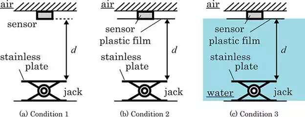
FIGURE 3.
Experimental setups for measuring sensor performance.
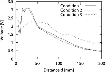
FIGURE 4.
Experimental measurements of sensor performance.
Figure 4 shows experimentally measured sensor performance. The plastic film utilized in Conditions 2 and 3 was the multilayered film described in Section 2. This film is commercially available and used to cover foods such as meats and vegetables. Under each condition, a multimeter was used to measure the output voltage of the infrared sensor for each distance d. The measured range was within 200 mm. The distance d was changed by 5 up to 100 mm and 10 up to 200 mm under each experiment. Performance was measured in the perpendicular direction. As shown in Figure 4, the results observed using Conditions 1 and 2 showed similar tendencies. The tendency of Condition 3 differed, however, as the magnetic permeability of water was dominant. Although the maximum output voltage was lower during Condition 3 than during Conditions 1 and 2, a peak was observed in the graph of Condition 3. This finding indicates that our robot can detect obstacles under water utilizing this sensor.
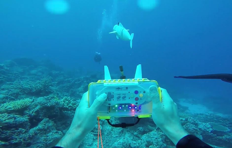
The performance of this infrared sensor indicated that our prototype was able to move autonomously. Figure 5 shows the prototype robot with one infrared sensor each mounted onto the two sides of its head section. This head section consists of the copolymer foam as the floating material. A polyethylene plate was utilized as an oscillation plate to generate the thrust force of the prototype in water. A microcontroller (Arduino Pro Mini 328 5 V, 16 MHz), a battery (9 V), a servo motor (RS304MD, Futaba), and insulating fluid (Fluorinert FC-3283, 3M) was encapsulated into a plastic film bag. The plastic film covering the internal components was composed of three layers: 12 μm thick antistatic polyethylene terephthalate (PET), 20 μm thick low-density (LD) polyethylene, and 50 μm thick antistatic linear low-density (LLD) polyethylene. The film was sealed by thermal adhesion of a vacuum packaging machine (TM-HV, Furukawa Mfg. Co., Ltd.). The prototype in Figure 5 measured 200 mm × 100 mm × 100 mm and weighed approximately 700 g.
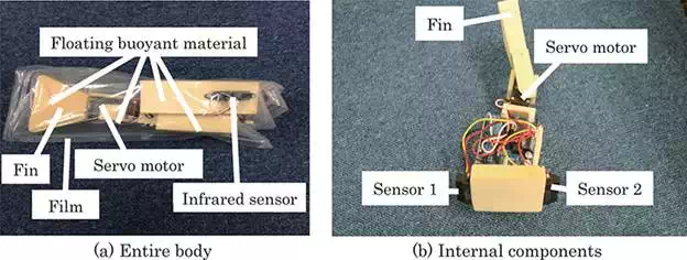
FIGURE 5.
Prototype robot with two infrared sensors.
Simple autonomous control of our prototype was implemented using the following strategy:
● if V1 ≥ Vth turn clockwise,
● otherwise, if V2 ≥ Vth turn counterclockwise,
● otherwise going forward.
Let V1 and V2 be the output voltages of Sensors 1 and 2, respectively, in Figure 5(b), and Vth be the threshold voltage to detect obstacles under water. Based on Figure 4, the voltage Vth was set at 1.65 V. Using this strategy, three moving modes were implemented in advance. During turning motions, the fin driven by the servo motor was moved 90° in either direction, at a frequency of approximately 2 Hz. During forward motions, the fin was moved ∓30°, at a frequency of approximately 1 Hz. Based on this strategy, the robot will turn clockwise when the combined voltages of Sensors 1 and 2 are greater than Vth.
Figure 6 shows the experimental environment. The experimental pool was 450 mm long and 600 mm wide. An aluminum plate, 300 mm long and 2 mm thick, was placed in the center of the pool as an obstacle. The body of the robot was at neutral buoyancy, allowing the robot to swim at a certain height. Figure 7 shows a typical experimental result captured by a camera. Cartesian coordinates were assigned to this pool to assess the movements of the prototype. Data were captured by the camera, and the position of the robot measured once per second. As shown in this figure, the robot could swim using combinations of forward and turning motions.
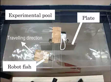
FIGURE 6.
Experiment environment.
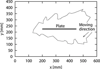
FIGURE 7.
Experiment results of autonomous control.
This section describes how to achieve autonomous locomotion using the electromagnetic-wave-transmitting properties of a plastic film. To detect an obstacle, two infrared sensors were mounted onto the body of the robot encapsulated by the plastic film. This film had electromagnetic-wave-transmitting properties, enabling not only noncontact sensors but other noncontact devices, such as wireless charging modules, and communication devices to be arranged within the device. Using these devices, we will develop a sophisticated fish-like robot that can feed itself under water and cooperative with other, similar robots in performing operations.
ATTITUDE CONTROL MECHANISM USING FLOATING BLOCKS
This section describes the design and control of robot attitude, especially its trim angle. The attitude of traditional underwater robots with bodies made of pressure tight casing can be changed or controlled by a movable weight within the body. In the control scheme called a trim mechanism, attitude is altered by a difference in density between the weight and air. Difficulties were also overcome by dynamic approaches, such as control schemes using the reaction force of internal rotors, the gyro effect of flywheels, and thruster forces for a neutral buoyant underwater robot. We used a static approach, based on the equilibrium between gravitational and buoyant forces, to control the attitude of our underwater robot. Specifically, we developed an attitude control system using movable floats on a dual-armed underwater robot. The attitude of the robot depends on the position of the floating blocks attached to a bar fixed onto the motor, with low-density floating blocks allowing the development of a lightweight underwater robot with attitude control. The attitude of our fish-like robot could be changed by the floating block and insulating fluid, with the placement of these components inside the robot determining its attitude under water. Because the mass of the insulating fluid differs from that of the floating block, the robot centers of gravity/buoyancy change as the positions of its components changes (Figure 8). As the low force/torque actuator can move the low-density floating block, the size of the robot body will tend to be small.
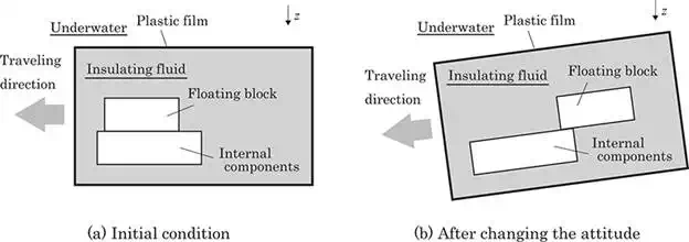
FIGURE 8.
Attitude control using a float arranged in a flexible body.
Based on the static properties of the robot, we were able to calculate the angle of attitude. These calculations require knowledge of the static properties of the internal components, floating blocks, and insulating fluid. The static properties of fluid used to fill the robot body are generally ignored in determining traditional trim angle control mechanisms because air is the usual insulating fluid and its density is negligible. To determine the angle of attitude, we considered a body-fixed reference frame attached to the robot in three-dimensional space (Figure 9). Within the body-fixed frame, the centers of gravity and of buoyancy of the internal components of the robot, including the fin, are defined as the vectors rrg and rrb, respectively; the centers of gravity and of buoyancy of the floating block are defined as the vectors rbg and rbb, respectively; and the centers of gravity and of buoyancy of the insulating fluid within the body are defined as the vectors rig and rib, respectively. Based on these definitions, the center of gravity rg and the center of buoyancy rb of the entire system can be described using the equations:


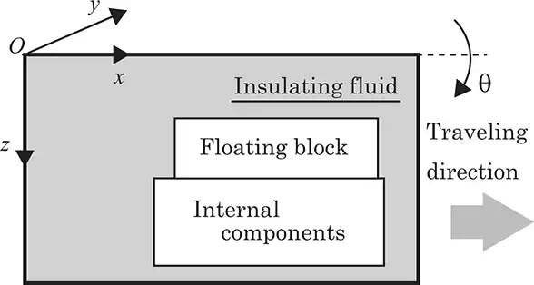
FIGURE 9.
Coordination of a fish-like robot.
In traditional underwater robots with bodies encased in pressure tight cases, the vectors rig and rib can be ignored because the fluid filling the body is air. However, we could select a unique rig because the shape of the insulating fluid was dependent on the arrangement of the internal components and floating block within the plastic-filmed body. The desired attitude angle θ about the x axis (see Figure 9) can be analytically or numerically calculated to satisfy the equation:

where rgx and rgz are the x and z vector components, respectively, of vector rg; and rbx and rbz are the xand z vector components, respectively, of vector rb.
Using Eqs. (1)–(3), we can determine the change in attitude changing based on the position of the floating block within the robot body. For simplicity, we assumed the following:
● A shift of floating material in the x direction in Figure 9 changes the attitude.
● The shape of the plastic-filmed body does not change when the attitude is changed.
● The positions of the internal components do not change when the attitude is changed.
Under these assumptions, rgz in Eq. (3) is a constant because the arrangement of internal components in the z direction does not change during changes in attitude. In addition, rbx and rbz in Eq. (3) are constants because the positions of the centers of buoyancy of the internal components, floating block, and insulating fluid do not change during changes in attitude. The angle θ will therefore depend on rgx. Using Eq. (1), rgx can be calculated as:

where rrgx, rbgx, and rigx are the x components of vectors rrg, rbg, and rig, respectively. Based on the above assumptions, the angle θ is dependent on the terms mbrbgx + mirigx because rrgx is a constant. As stated above, we cannot select a unique rig because the shape of the insulating fluid depends on the arrangement of the internal components and the floating block within the plastic-filmed body. A simple physical model (Figure 10) was used to investigate the magnitude of change in mbrbgx + mirigx as a function of the position of a floating block in insulating fluid. This figure shows a floating block within a massless rigid case filled with insulating fluid. Let the volumes of the floating block and insulating fluid be Vi and Vb, respectively; the masses of the floating block and insulating fluid be mi and mb, respectively; and the densities of the floating block and insulating fluid be ρi and ρb, respectively. The origin was set at the centroid of the massless case. The distances between the origin and the centers of gravity of the floating block and insulating fluid were expressed as |x1| and |x2|, respectively, with both centers of gravity assumed to be on the x axis. If the densities of the insulating fluid and the floating block are the same, the center of gravity of the whole system, including the insulating fluid and floating block, would correspond to the origin. Therefore, to balance the moment around the origin, the following equation should be satisfied:

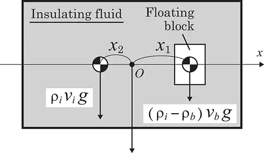
FIGURE 10.
A floating block within a massless case filled with insulating fluid.
Hence,

According to Eq. (6), the magnitude of the shift of the center of gravity of the entire system, or attitude, depends on the difference in density between the insulating fluid and the floating block. Therefore, if the density of the floating blocks is equal to that of the insulating fluid, the attitude could not be altered, even by changing the position of the floating blocks. Using Eq. (6), we also found that a greater difference in density would result in a greater change in attitude of our prototype despite its high weight. Thus, the proper fluid must be selected. For example, most industrial oils are less dense than water, whereas most fluids used to clean semiconductors are denser than water.
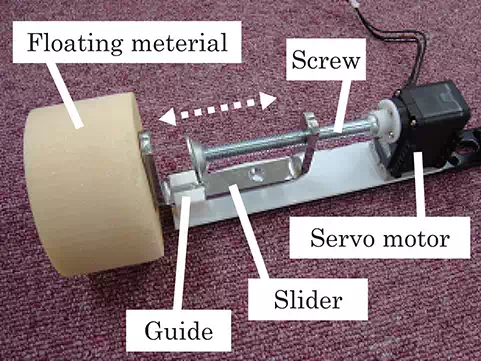
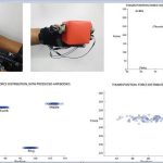
FIGURE 11.
Attitude control mechanism using a screw.
To validate our approach, we developed an attitude control mechanism in which a floating block was moved with a screw mechanism (Figure 11). This screw mechanism used friction to generate a high external holding force, resulting in a small-sized attitude control mechanism. The cylindrical floating block, measuring 78 mm in diameter and 50 mm in height, was made of copolymer foam (NiGK Corporation) with a specific gravity of approximate 0.2. A servomotor (AX-12A, Dynamixel) was attached to the actuator of the attitude control system. This system used an Arduino UNO (ver. R3) as a microcontroller. The floating block was mounted onto a metal slider. A guide mechanism made of a resin material was used to regulate the direction of movement of the slider, allowing the floating block to move in a straight line along the guide mechanism. Two 9 V dry-cell batteries were used to drive the servomotor and the microcontroller, respectively.
The performance of the prototype was assessed by performing several experiments in air and under water. In air, the maximum displacement of the floating block was 40 mm, and its speed was 0.73 mm/s. For tests under water, we utilized a TM-HV (Furukawa Mfg. Co., Ltd.) to seal the plastic film of the robot body and Fluorinert FC-3283 (3M), with a specific gravity of approximately 1.8, as the insulating fluid (Figure 12). A cylindrical pipe made of resin was not in direct contact with the control mechanism or the plastic film, allowing smooth motion during the experiment. The prototype, including the resin pipe, was 260 mm in length and 80 mm in diameter, and weighed 1785 g. Figure 13 shows the time transition of the angle of attitude. The initial angle was set at 0 rad, and a camera was used to map its position every 3 s. The convergent value and average speed of the change in attitude were approximately 0.22 rad and 3.6 × 10⁻³rad/s, respectively.
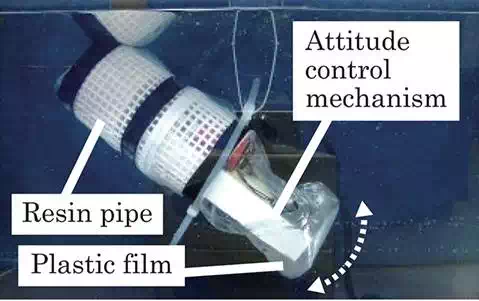
FIGURE 12.
Motion test (under water).
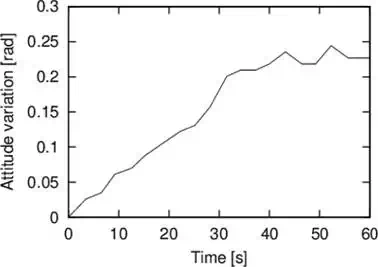
FIGURE 13.
Change in angle of attitude over time.
This section describes the use of a movable floating block within the outer surface of the fish-like robot to achieve attitude control. The arrangement of the floating block determines the attitude depending on the differences in density between the insulating fluid and the floating block. If the density of the floating block is low, a low force/torque actuator can be used to move the floating block, allowing the development of a small-sized body. The arrangement of the internal components, insulating fluid, and floating block could be altered not only by the movement of the float within the body but also by the inflection of the outer surface itself. One motor may generate sufficient propulsion force to maintain the attitude of the robot body. We intend to develop a sophisticated fish-like robot that can search autonomously for underwater structures, with the type of robot depending on the situations in which it will be utilized.
Conclusion
This chapter has described a fish-like underwater robot with an outer surface composed of a flexible thin plastic film. The internal components of the robot, including a servo motor, microcontroller, battery, and floating blocks, were encapsulated in a plastic-filmed bag using a vacuum packaging machine. This vacuum packaging machine enabled rapid, low-cost fabrication of fish-like robots with a plastic-filmed outer surface. To simplify its waterproofing and pressure resistance properties, the internal components of the fish-like robot was filled with insulating fluid. Autonomous and attitude control schemes were proposed based on the characteristics of these fish-like robots. As the encapsulating thin plastic film has electromagnetic-wave-transmitting property, a noncontact sensor could be arranged within the robot. We also designed an attitude control mechanism employing floating blocks, with the attitude of our prototype determined by the arrangement of the floating block and dependent on the differential densities of the floating block and insulating fluid. Attitude control was found to vary more when the insulating fluid was denser than water. In literature, we have pointed that insulating fluids, less dense than water, could be used as floating materials to achieve neutral buoyancy. Therefore, the volume of insulating fluid within a prototype should be carefully determined according to the moving performance.